Star-delta (or wye-delta) starting is a basic method to lower the starting current of a motor. It works with squirrel-cage induction motors that are typically delta-connected during normal operation. This method is best for motors where each winding end is individually connected to terminals.
Reducing the motor’s starting current also lowers its starting torque. So, star-delta starting works well for motors that don’t need much torque until after they start. However, the starting time is longer compared to directly starting the motor. This difference becomes more noticeable when the motor has to move larger loads.
When initiating a star connection, the phase voltage is applied to the motor windings, resulting in a winding current of IWY = IWΔ/√3. Due to the vectorial addition of winding currents in a delta connection, IeY equals IeΔ/3.
There are three main types of star-delta starting:
- Normal star-delta starting: This is the basic method without any special features.
- Star-delta starting with closed transition: This method ensures a smooth transition between star and delta configurations during starting.
- Amplified star-delta starting: This variation enhances the standard star-delta starting method for specific applications.
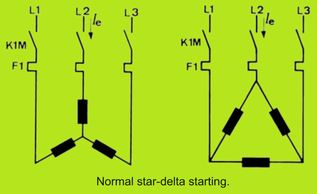
Normal star-delta starting
During the star-delta starting process, the motor’s connections and switching-over procedure play a crucial role. At the initiation of starting, the supply voltage is applied to the star-connected motor windings. In this configuration, the starting torque and current are approximately 30% of the values for delta connection. Due to the reduced torque in the star connection, the motor doesn’t quite reach its rated speed.
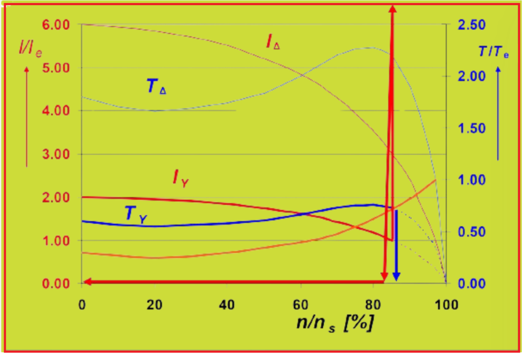
After the star-connected start-up, the windings are switched-over to delta connection. This switching causes a surge in current, the magnitude of which depends on various factors. In an ideal scenario, illustrated in Figure 2, the motor nearly reaches its rated speed during the first stage, as the load torque during starting is relatively low. The surge in current during the switching-over process is approximately the same size as the starting current.


The switching-over process is typically automatic, although manual switching is rare. It’s managed by a timing relay set to the required operating period of the star contactor. There’s an essential time gap between switching off the star contactor and activating the delta contactor. This gap ensures that any breaking arc in the star contactor is fully extinguished before the delta contactor engages. If the switching-over happens too quickly, the breaking arc can cause a short-circuit, triggering the short-circuit protection and disconnecting the circuit.
Conversely, if the switching interval is too long, the motor’s speed decreases during the de-energized interval. Depending on the motor’s inertial mass and load, this reduction in speed can lead to a significant in-rush current when the delta connection is engaged. This scenario defeats the purpose of the star-delta start-up.
To find the optimal balance, a sufficient but not excessive switching interval between the star and delta contactors is essential. Small contactors with short pull-in and dropout times typically use electronic timing relays with a switching-over delay of around 50 ms. Larger contactors have an inherent switching delay of more than 25 ms. In such cases, timing relays without additional switching delay can be employed to achieve the optimum switching interval length. Additionally, to prevent phase short-circuits, the star and delta contactors are mechanically interlocked.

If the delta contactor is activated via an auxiliary contactor, such as in low control voltage situations, no switching-over delay is required on the timing relay. The switching interval is determined by the combined making delay times of the auxiliary and delta contactors.
Faults like those shown in Fig. 3 and Fig. 4 can be avoided with an interruption-free (closed transition) star-delta circuit. This circuit ensures smooth transitions between the star and delta configurations, preventing short-circuits or other issues during switching.
When the load torque is too high, the motor only reaches a fraction of its rated speed in the star-connected mode and remains stuck at this lower speed. In such cases, the switching process continues as shown in Fig. 5, and the intended purpose of the star-delta start-up is not achieved.
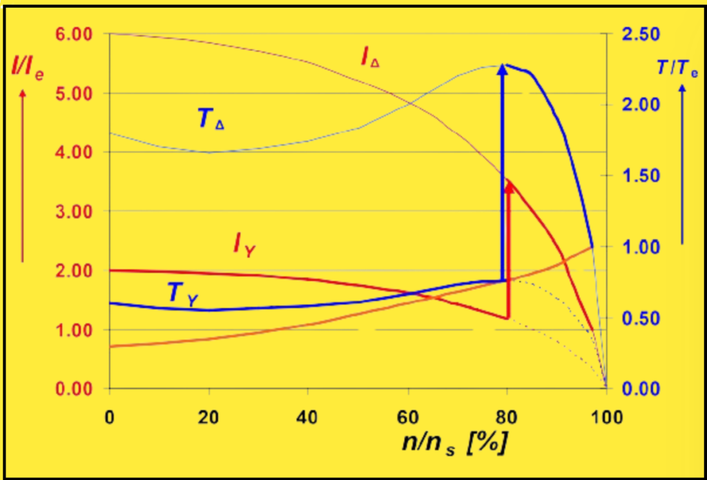
Furthermore, in this condition, the contactors must handle a multiple of the motor’s rated current during switching. For example, in Fig. 5, the breaking current is approximately 1.3 times the motor’s rated current (1.3 · Iemotor). The star contactor is typically selected based on a fraction of the motor’s rated current Ie(Y contactor) = 0.34 · Iemotor. Therefore, the star contactor must handle approximately 4 times its rated current during switching.
1.3/0.34 ≈ 4 · Ie(Y contactor)
This increased current handling requirement means that the contactors operate under AC-4 conditions, which can reduce their electrical lifespan. To address this issue, a motor designed for amplified star-delta starting should be used.
How to Select the starter components?
In a star-delta circuit as depicted in Fig. 3.3-6, the main contactor, delta contactor, and motor protection relays are connected in series to the motor windings when in delta mode, as shown in Fig. 3.3-7. This means that these devices bear the load of the phase current (Ip).
Ip = Ie/√3 = 0.58 · Ie

When selecting contactors, the following values are considered for starting times of up to 15 seconds and up to 12 starts per hour. However, for heavy-duty starting or higher operation frequencies, it’s advisable to opt for larger contactors like K3M, and possibly K1M as well.
Additionally, it’s crucial to review the electrical lifespan of the contactors, particularly the star contactor. If, for instance, switching-over occurs at too low a speed, the star contactor may need to break many times its rated current, as illustrated in Fig. 5. This scenario would significantly reduce its electrical lifespan.

In standard star-delta starting, the switchgear must be rated for specific operational currents:

Motor connection for clockwise and counterclockwise direction of rotation.
When connecting a motor for clockwise and counterclockwise rotation, it’s important to consider potential transient processes that could occur when the delta contactor connects at adverse vectorial positions of the supply voltage and the rotor field. These transients might lead to larger current peaks compared to switching on the delta-connected motor normally. Such peaks could exceed the making capacity of the contactors, resulting in contact welding.
To mitigate these transient currents, appropriate wiring of the main circuit can be employed, as shown in Fig. 8. This not only reduces the load on the contactors but also diminishes the dynamic stress on the windings’ heads in the motor.
1. Lower transient currents peaks with correct wiring (clockwise rotation).
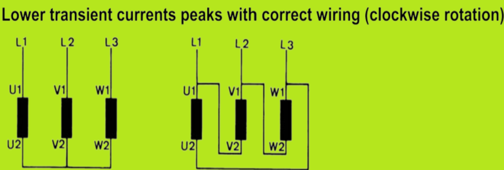
During the de-energized switching interval, the rotor falls back against the rotating field of the power supply. This movement induces a decaying residual voltage in the stator, as illustrated in the voltage phasor diagram in Figure 9, where the pole conductor L1 is represented as UL1’-N.

When connecting to the delta configuration (as shown in Fig. 8 and Fig. 9), the mains voltage UL1-L3 is applied to the stator winding, which still contains this residual voltage. However, the differential voltage (∆U) resulting from this residual voltage is relatively small, thanks to the favorable vectorial position of the residual voltage UL1’-N and the supply voltage UL1-L3, which are approximately oriented in the same direction. Consequently, the current surge generated by this resultant voltage also remains small. This setup helps prevent excessive current peaks during motor connection for both clockwise and counterclockwise rotation.
2. High transient current surge with incorrect wiring.
When the motor terminals are connected according to Fig. 3.3-10, the motor also turns clockwise. However, this wiring configuration can lead to a high transient current surge due to incorrect wiring.
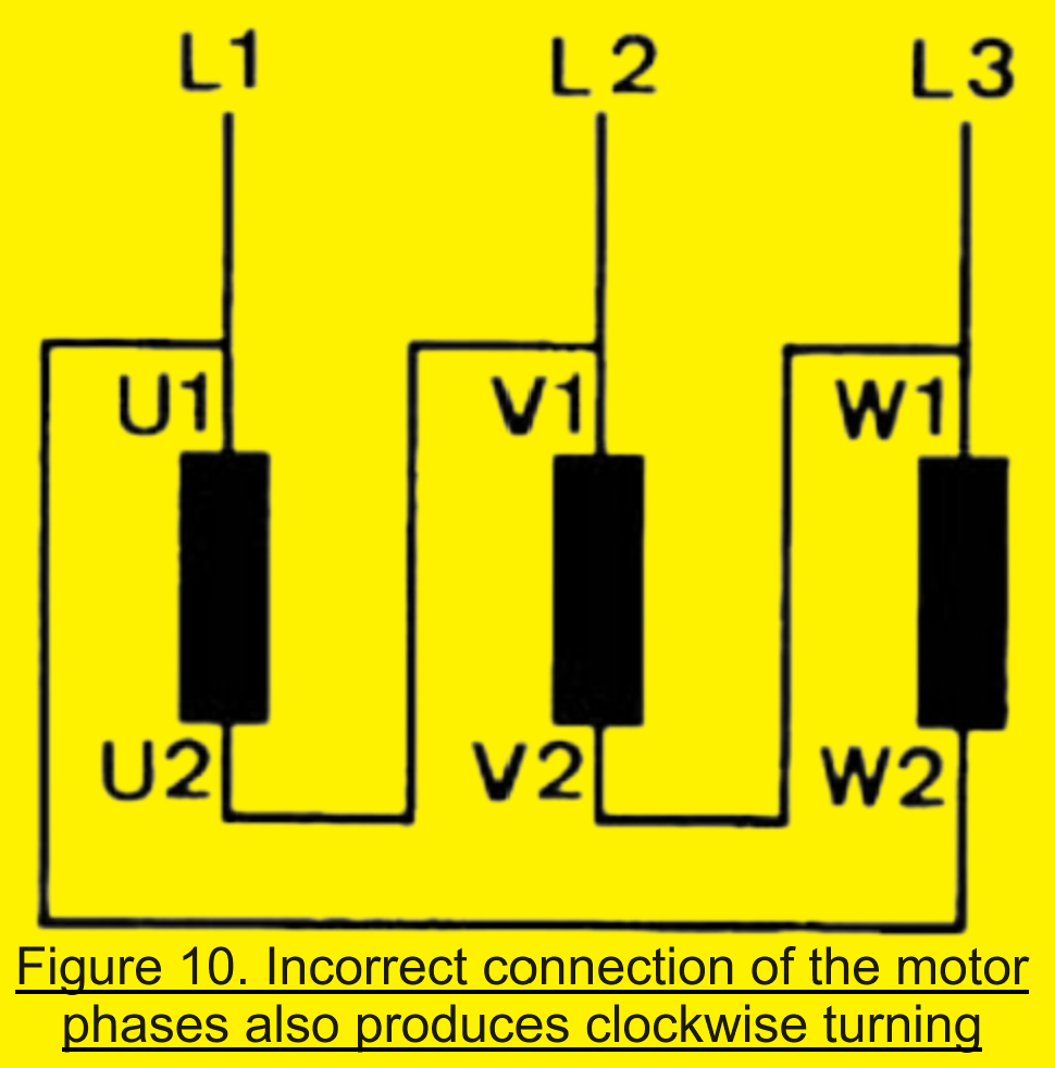
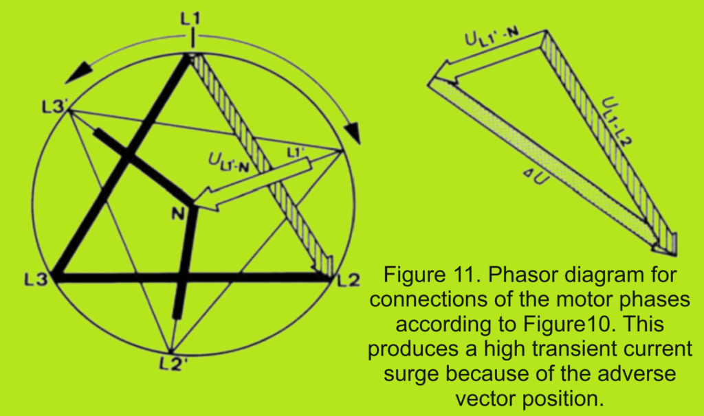
During the switching interval, a decaying residual voltage with a lagging phase position acts in the stator. Upon switching to the delta configuration, the phase winding with the phasor UL1’-N is connected to the supply phase UL1-L2. These two voltages have completely different vectorial directions, resulting in a high differential voltage (∆U). This high differential voltage leads to a correspondingly high transient current surge.
Switching from star to delta produces the phasor diagram shown in Figure 11, illustrating the impact of the wiring configuration on the phase voltages during this transition.
3. Counterclockwise sense of rotation.
To achieve a counterclockwise sense of rotation in the motor, simply swapping two phases at any point is not sufficient. This would result in the same relationships described previously. Instead, to minimize the transient current surge during the transition from star to delta connection, the wiring must be arranged as shown in Figure 12. This wiring configuration ensures the proper phase relationships needed for counterclockwise rotation while also minimizing the potential for high transient currents during switching.

Influence of the third harmonic on motor protection relays.
In motors with less core iron, like refrigeration or submersible pump motors, connecting them in delta mode can cause the third harmonic and its harmonics to be generated in the windings due to iron saturation. This happens because the third harmonic’s triple frequency makes the currents align in a circle through the windings. When in star mode, this doesn’t occur because the motor’s star point isn’t connected to the mains.
These harmonic currents can be quite significant, up to 30% or more of the basic current. Instruments that show the true r.m.s. value can measure the entire winding current accurately, but those displaying only the mean value can’t detect the harmonic component.
The third harmonic contributes to heating up the motor windings, but manufacturers consider this when determining the motor’s rated load to ensure it’s not exceeded. Therefore, motor protection devices for direct starting in delta mode should always be set to the motor’s rated operational current.
In a star-delta starter, the motor protective device is connected in series to the motor windings. If it’s normally set to 0.58 times the rated current (0.58 · Ie), it might trip too early due to the extra harmonics. In such cases, the actual r.m.s. value of the winding current should be measured, and the protective device’s setting should be increased by the percentage of the harmonic current. This is especially important for motor protective devices like bimetal relays, which base their trip characteristic on the r.m.s. value of the current.
Electronic motor protective devices might use different measuring principles, like the peak value of the current. In these cases, adjustments to the settings should be based on practical tests.
Uninterrupted star-delta starting (closed transition).
The uninterrupted star-delta starting, also known as closed transition starting, employs a circuit depicted in Figure 14 and Figure 15. This circuit ensures that the motor speed doesn’t decay during the star-delta switching process, and it keeps the subsequent current peak small.
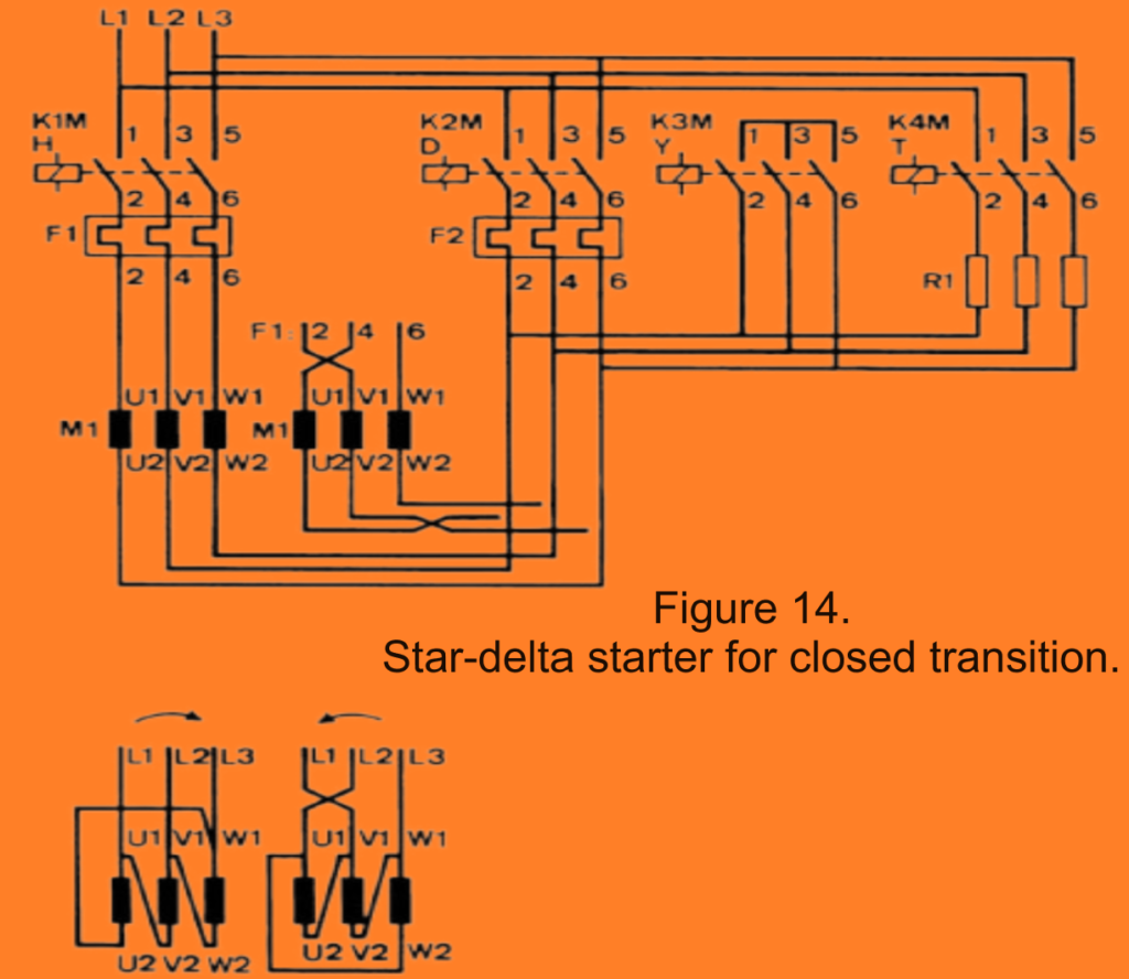
Before opening the star contactor, a fourth contactor, K4M (transition contactor), establishes the motor circuit via resistances in delta configuration. This means that the motor current continues flowing during the switching-over process (as shown in Figure 13), and the motor speed hardly decreases. Subsequently, the delta contactor, K2M, finalizes the operation and disengages the transition contactor, K4M.

Similar to the normal star-delta circuit, this setup is suitable for starting with small load torques.

The four switching steps of the closed transition star-delta circuit are as follows:
A. Starting in star connection.
B. Switching-over: Both star and transition contactors are closed.
C. Switching-over: Delta circuit via the transition contactor and resistors.
D. Operation in the normal delta circuit.
Rating of starters.
.")
In the starter for closed transition, unlike in the normal star-delta circuit, the star contactor (K3M) has the same rating as the main and delta contactors for two reasons:
- The K3M star contactor needs to break the star current of the motor and the current flowing through the transition resistances. Typically, a current of approximately 1.5 times the rated current (Ie) flows in the transition resistors. Therefore, a correspondingly higher contact rating is required for the star contactor.
- The closed transition star-delta circuit is often utilized in plants with higher operation frequencies, necessitating a longer electrical lifespan for the components involved. This requirement further justifies the need for a star contactor with a higher rating.
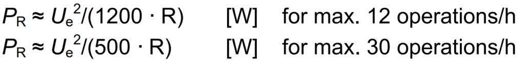
The resistors in the closed transition starter are only loaded for a maximum of 0.1 seconds (short-time duty). However, in most cases, only the continuous load capacity of the resistors is known. For wired ceramic-tube resistors, the required continuous load capacity (PR) for selection can be calculated using the following approximation formulas:
Amplified star-delta starting.
Amplified star-delta starting is used when a large load torque requires a higher starting torque than what’s achievable with normal star connection (as shown in Fig. 3.3-5). With amplified star-delta starting, a larger motor torque can be attained, but it also leads to an increase in the starting current.
There are two methods for amplified star-delta starting:
1. Mixed star-delta starting.
- In this method, the motor windings are typically divided into two equal halves.
- During starting, one half of the windings is delta-connected while the other half is star-connected (as illustrated in Figure 16).
- The starting current in the star connection is approximately 2 to 4 times the rated current (Ie), resulting in a correspondingly larger starting torque.
 and in operation (∆)")
2. Part-winding star-delta starting.
In part-winding star-delta starting, similar to mixed star-delta starting, the motor windings are divided. However, in this method, only one part of the entire winding, typically the main winding, is used in the star connection (as illustrated in Figure 17). The starting current in the star connection ranges from 2 to 4 times the rated current (Ie), depending on the tapping used, resulting in a larger breakaway torque.
 and in operation (∆)")
Regarding the ratings of the starter components, except for the star contactor, contactors, and motor protective devices, they remain the same as in the “normal” star-delta circuit (as discussed in above section). The star contactor should be selected for 0.5 to 0.58 times the rated current (Ie) due to the larger starting current in this configuration.
It’s important to ensure a sufficiently long switching interval for the transition from star to delta operation, as discussed in above section of this article. Using a closed transition star-delta connection, is possible in both mixed and part-winding star-delta starting methods. In cases with very large load torques, it may even be necessary. The transition resistor and the transition contactor should be rated.