The main points and Keywords to be discussed in this article are testing and commissioning of ac ups system. ups system electricala. Inverter. Static transfer switch overload test. Inverter overload test.
TOOLS AND EQUIPMENT TESTING AND COMMISSIONING OF ELECTRICAL EQUIPMENT
Tools and equipment should be in good condition for use in the construction area. All test equipment required to be calibrated not more than 3 months before the date of test. All equipment calibration “original” certificates should be presented at site.
These includes but not limited to the following:
Common Hand Tools
Digital Volt-ohm Meter
500/5000V MEGGER
Current Tester (Multi-Amp or equal)
Torque Wrench
Ductor (Micro ohm Meter)
Protective Relay Test Set
Thermometer
Oscilloscope
Load Bank
Manufacturer’s Instruction Manuals
Personal Protective Equipments
Timing Tester
Hydrometer
Relay testing set
DLRO
PROCEDURES FOR TESTING AND COMMISSIONING OF AC UPS SYSTEM
GENERAL PREPARATORY WORKS
COMPANY shall appoint qualified employees as their ‘competent persons’. Such persons shall be capable of working safely and shall be knowledgeable on the precautionary techniques, personnel protective equipment, shielding and insulating materials and tools.
All permanent and consumable materials shall prepare prior to testing.
Manpower, equipment, tools and other logistics shall be prepared and ready for installation.
Prepare the workplace such as barricading the area and housekeeping.
Review the AC/DC control schematic of the disconnect switch assembly. All connection diagram vendor and IFC drawing shall be available in the work area.
Review all technical specifications, operating manuals and previous inspection data if appropriate.
Electrically Hazardous Task Plan / Permit shall be completed and signed before any work proceeds.
AC UPS SYSTEM ELCTRICAL COMMISSIONING
Visual Inspection
Compare equipment nameplate information data with actual operating conditions, drawings and specifications.
Inspect the physical condition of all electrical and mechanical components for deterioration and missing, broken, or loose parts, etc. This includes the inspection of insulators, insulation materials, sign of overheating or electric sparks and door fastener functionality.
Check for proper wiring and terminal connection are done.
Check that all grounding is securely connected (including star neutral points).
Check cleanliness of interior of cubicle, clean using manufactures approved method and material.
The main keywords for this article are testing and commissioning of electrical equipment, ups test, commissioning and testing and commissioning of dc ups system.
TOOLS AND EQUIPMENT TESTING AND COMMISSIONING OF ELECTRICAL EQUIPMENT
Tools and equipment should be in good condition for use in the construction area. All test equipment required to be calibrated not more than 3 months before the date of test. All equipment calibration “original” certificates should be presented at site.
These includes but not limited to the following:
Common Hand Tools
Digital Volt-ohm Meter
500/5000V MEGGER
Current Tester (Multi-Amp or equal)
Torque Wrench
Ductor (Micro ohm Meter)
Protective Relay Test Set
Thermometer
Oscilloscope
Load Bank
Manufacturer’s Instruction Manuals
Personal Protective Equipments
Timing Tester
Hydrometer
Relay testing set
DLRO
PROCEDURES TESTING AND COMMISSIONING OF ELECTRICAL EQUIPMENT
GENERAL PREPARATORY WORKS
COMPANY shall appoint qualified employees as their ‘competent persons’. Such persons shall be capable of working safely and shall be knowledgeable on the precautionary techniques, personnel protective equipment, shielding and insulating materials and tools.
All permanent and consumable materials shall prepare prior to testing.
Manpower, equipment, tools and other logistics shall be prepared and ready for installation.
Prepare the workplace such as barricading the area and housekeeping.
Review the AC/DC control schematic of the disconnect switch assembly. All connection diagram vendor and IFC drawing shall be available in the work area.
Review all technical specifications, operating manuals and previous inspection data if appropriate.
Electrically Hazardous Task Plan / Permit shall be completed and signed before any work proceeds.
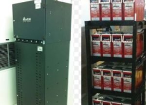
DC UPS SYSTEM
Visual Inspection
Compare equipment nameplate information data with actual operating conditions, drawings and specifications.
Inspect the physical condition of all electrical and mechanical components for deterioration and missing, broken, or loose parts, etc. Complete visual inspection of the battery system as follows.
Broken or missing flame arresters and caps.
Sediment in the bottom of batteries.
Cracked, swelled, or damaged battery cases.
Abnormal battery plate appearance.
Visible corrosion on battery terminals or battery rack.
Normal excessive ambient temperature in battery room.
Normal excessive ambient humidity in battery room.
Normal excessive dust or dirt in battery room.
Wet floor around batteries and electrolyte on tops of batteries.
Inspect for battery and racks are properly installed.
Check for proper battery terminal and grounding connection are done.
Tighten main current carrying part (terminal connection, etc.) to the manufacture torque specification. If such information is not available, tighten in accordance with SA-P-000 page 4. Ductor test may also be used to confirm proper connection after initial torque test has been completed.
This procedure describes the methods and requirements in the start-up and commissioning of the Rectifier / Charger System of UPS. The main keywords for this article are battery charger, rectifier, Battery charger test procedure, Load Test Rectifier, Load Test charger.
GENERAL REQUIREMENTS
✓ Each item should be checked in accordance with the requirements in specification, drawings and manufacturer’s instruction and technical data as required to verify completeness of installation. ✓ All necessary verification activities for the equipment should be completed before implementation of start-up and commissioning.
SAFETY PRECAUTIONS
✓ Start-up and commissioning must be carried out by a qualified engineer, trained by the manufacturer or one of its agents. Failure to observe this will invalidate any future claims. ✓ The rectifier/ charger will contain potentially lethal voltages at all times once power is applied from the main distribution panel. Safety tagging and clearance procedure should be utilized in the start-up and commissioning. ✓ Clear the area of all unauthorized personnel and install barricades if possible to restrict entry of unauthorized persons. ✓ Tag the power disconnect switches on the distribution panel board which supplies power to the rectifier/ charger before working on the equipment.
Test Equipment & Tools Rectifier / Charger System
✓ Digital Multimeter. ✓ Phase Sequence Meter. ✓ Temperature Measuring Equipment. ✓ Load bank.
What Inspection need to be done.
✓ Inspect all wires and conductor insulation for damage. ✓ Inspect all wiring connections to the capacitor banks. Re-tighten if necessary. ✓ Check all terminal and breaker connections for tightness. Re-tighten if necessary. ✓ Remove and foreign objects from the components or the interior area of the unit. Make sure air passages are clear and free of debris. Re-tighten if necessary. WARNING: HAZARDOUS VOLTAGES ARE PRESENT IN THE EQUIPMENT THROUGHOUT THE MAJORITY OF THE START-UP PROCEDUR. PROCEED WITH CAUTION. ✓ Carry out a thorough visual inspection of the equipment. Check the security of all cable terminations and ensure that all electrical connectors, plugs and sockets are correctly located and firmly fitted.
START- UP: CAUTION!!!! It is assumed that the installation is complete, the system has been personalized and set-up accordingly.
Main tests are Transformer testing, transformer oil testing, transformer winding, current transformer, Transformer Ratio test.
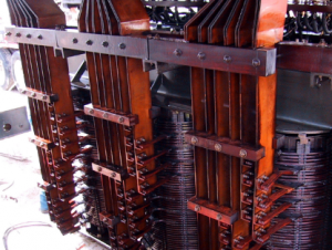
TRANSFORMER TESTING ON SITE
After a transformer has been completely assembled on site, it must be tested to confirm successful shipment and correct assembly. All tests must be carried out with instruments that have traceable, valid calibration. These instructions are intended to provide guidelines in the test of transformers to maintain their quality and reliability.
They are intended for the guidance of personnel who have been trained for, or who have experience in test of high-voltage electrical power equipment, including the use of good safety practices. These instructions are intended to supplement, and not eliminate the necessity for such training.
The Transformer testing results are to be recorded on a Test Record. The second sheet of this Transformer testing Record is a list of all possible tests, some of which may not be applicable. When the on-site project manager or the assembly supervision has marked all applicable tests, this sheet forms an order-bound directive for the tests to be carried out.
Main tests are Transformer testing, transformer oil testing, transformer winding, current transformer,Transformer Ratio test.
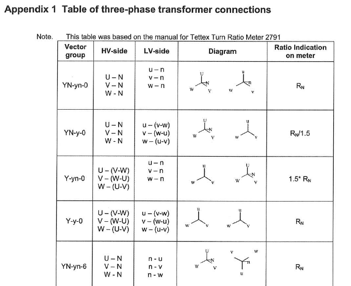
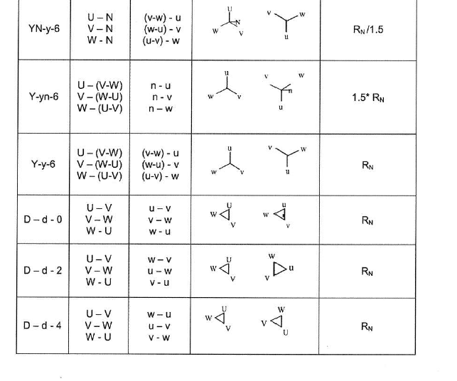
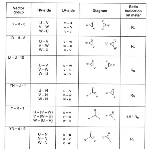
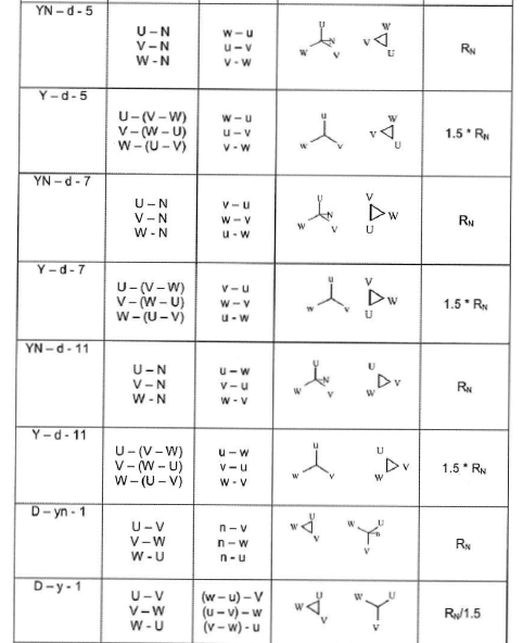
Transformer Ratio test
The Transformer Ratio test is used to confirm that the winding turns ratio is consistent with the voltage ratio as shown on the Nameplate.
Transformer Ratio test This is done primarily to check for shipping damage and to confirm that any tap-changer leads installed in the field have been correctly connected. In addition to the ratio measurement, exciting current is also often measured. The ratio measurements is normally done with a ratio bridge. Table of three-phase transformer connections Appendix 1. Transformer Ratio test
Transformer Winding resistance test
Measure the resistance of each winding at the rated and extreme tap positions and compare the results to the original value in the Factory test report. If the Tap Changer connections have been made at site, measuring at all positions should be done. Transformer winding Resistance is dependent on the temperature of the winding. The mean temperature of the oil is representative of the winding temperature, and providing that the oil is at a uniform temperature, the top oil temperature gauge value can be used. Resistance comparison must always be made at a common temperature. The conversion formula for copper and aluminium transformer winding is show below. The formula giving the relation between the resistance and the temperature is:
where RT2 = Resistance of the winding at temperature T2 RT1 = Resistance of the winding at temperature T1 K = 234.5 for winding made of copper ace to IEEE, K = 235 for winding made of copper ace IEC K = 225.0 for winding made of aluminium The time constant may be very long when low voltage and low current sources are used.
Note:
A high voltage surge occurs at interruption of DC current at end of measurements. A discharge circuit should be used. Eg. see IEEE Std 62 figure 2.
Main tests are Transformer testing, transformer oil testing, transformer winding, current transformer, Transformer Ratio test.
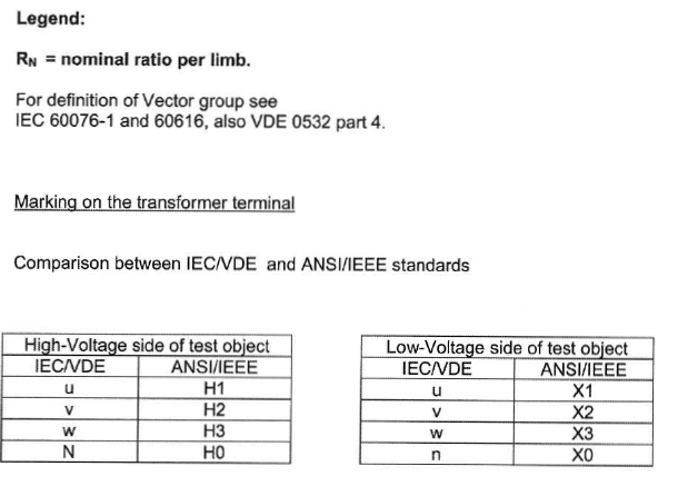
Transformer Check of vector group
The purpose of this series of tests is to check the polarity and the phase relationship of the multiple windings in a transformer. The test is carried out simultaneously with the transformer turns ratio test when using a turns ratio test set. In order to define the connection of a three-phase transformer and to facilitate the parallel connection with other transformers, the international standards prescribe specific vector groups. Every country has its own designation for the vector groups. IEC and IEEE (in USA) have recommended a method that will result in standardized and fully defined designations.
Transformer Insulation resistance test
Insulation resistance can give some information of the integrity of the insulation structure. As an insulation structure begins to deteriorate due to contamination and moisture, the insulation resistance will decrease. The test equipment used is a DC insulation tester (Megger). It is essential that it is of a type, which is suitable for measurement on transformers and transformer core insulation. Ensure that bushings are clean and dry. Insulation resistance is temperature dependence why it is important that the oil temperature is noted. After the test has been completed, all terminals shall be grounded time enough to allow any trapped charge to decay to negligible value.
Transformer main windings
When conducting an insulation resistance test on transformer windings, a 2.5 or a 5 kV megger can be used. Test every winding to ground and between each winding. Make sure that the bushing porcelains are cleaned since dirt deteriorates the insulation resistance. The transformer tank must be grounded during the test. If the insulation resistance is 1 Mn/kV system voltage for the winding, it is acceptable. If lower values are measured, this must be reported to an ABB representative. According to IEEE the following shall be measured. High voltage to low voltage and ground, low voltage to high voltage and ground.