Following topics to be discussed here.
1. SCOPE
2. SAFETY
3. OXYFUEL GAS CUTTING (FGW)
3.1 Cutting Operation
3.2 Fuel Gases Used
3.3 Equipment
4. ARC CUTTING (AC)
4.1 Metal-Arc Cutting (MAC)
4.2 Air Carbon Arc Cutting (AAC)
4.3 Plasma-Arc Cutting (PAC)
FIGURE
1 Portable Machine Making Straight Cut
2 Portable Machine with Attachment for Making Radius Cut
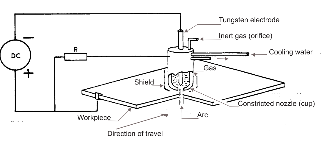
3 Basic Plasma-arc Cutting Circuit
4 Typical Portable Assembly of Plasma Arc Equipment
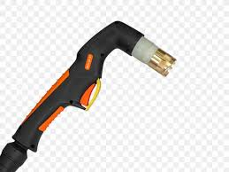
5 Plasma-arc Cutting Torches
TABLES
TABLE IA Oxyacetylene Hand Flame Cutting of Clean, Mild Steel 3.2 mm to 304.8 mm Thick, Not Preheated.
TABLE IB Data for Oxyacetylene Hand Flame Cutting of Clean Mild Steel 1/8 inch to 12 inches Thick, Not Preheated.
TABLE IIA Performance Characteristics of Solid Core Electrodes for Metal-arc Cutting Steel Plates (Metric Units).
TABLE IIB Performance Characteristics of Solid Core Electrodes for Metal-arc Cutting Steel Plates (Imperial Units).
TABLE III Copper-Clad Electrodes and Polarity.
TABLE IV Direct Current Reverse Polarity.
TABLE VA Operating Conditions and Recommended Gas-Flow Rates for Plasma-Arc Cutting of Steel and Cast Iron (Metric Units).
TABLE VB Operating Conditions and Recommended Gas-Flow Rates for Plasma-Arc Cutting of Steel and Cast Iron (Imperial Units).
TABLE VIA Operating Conditions and Recommended Gas-Flow Rates for Plasma-Arc Cutting of Stainless Steel and Aluminum (Metric Units).
TABLE VIB Operating Conditions and Recommended Gas-Flow Rates for Plasma-Arc Cutting of Stainless Steel and Aluminum (Imperial Units).
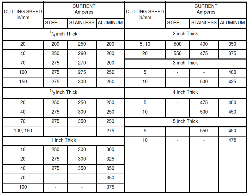
TABLE VIIA Typical Current Levels used for Plasma-Arc Cutting of Steel,Stainless Steel, and Aluminum at Various Thicknesses.
TABLE VIIB Typical Current Levels used for Plasma-Arc Cutting of Steel,Stainless Steel, and Aluminum at Various Thicknesses (Imperial Units).
Thermal Cutting Practices
1. Scope
This standard provides practices applied in thermal cutting.
2. Safety
Safe practices prescribed in SW50W shall be followed on plant sites.
3. Oxyfuel Gas Cutting (FGW)
The quality of the cut by this method is generally good and is more economical than the other methods.
3.1 Cutting Operation
3.1.1 The cutting of iron or steel by the oxyfuel gas cutting process involves the direction of a jet of pure oxygen onto an area that is preheated, with the preheat flames surrounding the cutting oxygen jet.
3.1.2 In all oxyfuel gas cutting, the preheating flames are first turned on and directed to the edge of the metal where the cut is to be started. The edge is heated until a bright red spot appears. The cutting valve is then opened and, with the preheat flames still burning, the torch is advanced at a uniform rate along the line of cut. If the speed of travel is too great, the slag and oxide emerging from the bottom of the cut will trail back at an angle. When this is the case, a poor quality cut usually results, and there is a danger of the stream suddenly failing to penetrate the steel. The proper cutting speed may be determined by a slight drag in the oxide emerging stream. In other words, the oxide stream at
the base of the cut trails the cutting tip slightly.
3.1.3 In Table I, data for hand-cutting carbon steel 3.2 to 305 mm (1/8 to 12 inches) thick with oxyacetylene is shown. Machine cutting speeds and gas consumptions are similar to those as shown in Table I except that the cutting oxygen pressures and speeds are slightly higher.
3.1.4 This cutting process is by rapid oxidation of the metal. In cutting carbon steels, the oxides formed have melting temperatures lower than the melting point of the steel. Thus, the oxides melt off as fast as formed and do not hinder the oxidation process. Other materials, for example: stainless steels, cast iron, aluminum bronzes, and Hastelloy alloys are difficult to cut by the oxyfuel gas process. The reason is that the oxides formed have melting temperatures higher than the melting point of the parent metal. An insulating coating of oxides thus formed hampers and, in the case of some oxides (for example: chromium oxide on stainless steel), completely stops the oxidation process. The cutting of these metals is discussed in section 4.
3.2 Fuel Gases Used
3.2.1 Acetylene, propane, natural gas, and methylacetylene propadiene (Mapp) are the most commonly used fuel gases. Acetylene has the highest flame temperature and the most widely used fuel for cutting. It is available readily, easy to handle, and its high combustion intensity permits a fast start.
3.2.2 Propane is being used at a number of plants because of its relatively low cost in large quantities and availability since it is also used for purposes other than cutting. For proper combustion, propane requires about four to five times its volume of oxygen, to some extent offsetting the economic benefits in light cutting. In heavy cutting and in large-scale cutting operations, propane is usually more efficient. These considerations hold true also for natural gas and Mapp.
3.3 Equipment
Since acetylene is the most versatile fuel gas, the following practices are applicable to oxyacetylene cutting only.
3.3.1 The source of gas supply can be pipeline, manifold, or cylinder. The pressure regulators are attached to these sources. The regulators employed are similar to those used for welding operations. For the cutting operations where the oxygen consumption is large, regulators capable of supplying large flows at the correct pressure shall be used.
3.3.2 A torch is connected to the gas supply by hose lines of sufficient size to conduct the volume of gases necessary for the cutting operation without excessive pressure drop. The hose lines are, in turn, connected to the outlet of the two pressure regulators (one for the fuel gas and one for the oxygen).
3.3.3 Several types of torches are employed in oxygen cutting. For manual cutting, a welding torch with a cutting attachment (or a hand-cutting torch) may be employed. These torches are not readily adaptable for machine cutting. Machine cutting equipment is generally purchased as a packaged unit. Special tips are necessary for fuel gases other than acetylene.
3.3.4 Portable machines usually travel on a straight section of track, which performs the function of guiding the torch along the line of cut, see Figure 1. These machines are used widely in the preparation of plate for welding (square cut or bevel), for ripping plate, and other purposes requiring a straight line cut. An attachment with an adjustable radius arm permits cutting circles, see Figure 2.
FIGURE 1 – Portable Machine Making Straight Cut

Figure 2 – Portable Machine with Attachment for Making Radius Cut

4. Arc Cutting (AC)
Arc cutting is based upon the conversion of electrical energy into heat within the confines of an electrical arc maintained between the work and the electrode. Because of the extremely high temperature developed in the electrical arc, it can be used to melt almost any material that conducts electricity and is employed for cutting metals. Arc cutting does not equal gas cutting from the standpoint of smoothness, quality, or accuracy of cut surfaces and is not used where high-quality accurate cuts are required. It is useful where smooth, uniform cut surfaces are not essential and
where severing is the main object, as in scrapping operations. Arc cutting also is used for metals not easily cut in any other manner, for example: cast iron, manganese steel, and large sections of nonferrous metals. Three procedures are employed: metal-arc, arc-air, and plasma-arc.
4.1 Metal-Arc Cutting (MAC)
4.1.1 The metal-arc procedure employs covered carbon steel welding electrodes.
4.1.2 The application of a heavily coated electrode to cutting is not always an economical process but is sometimes useful where other cutting methods are not available. Electrodes especially designed for cutting are available. The concentrated arc is advantageous in hole piercing operations. Edges are contaminated and should be ground to clean metal after cutting.
4.1.3 Plates 12.7 mm (1/2 in) thick or less can be cut by advancing the electrode along the line of cut. On heavier
plates, the electrode is pointed forward and moved from the top to the bottom of the cut so as to keep the bottom slightly ahead. The width of the cut is approximately constant for all electrodes 6.4 mm (1/4 in) in diameter or less. For performance characteristics, see Table II.
4.1.4 The cut produced by metal-arc cutting is ragged and generally is not satisfactory in the preparation of parts for welding without considerable trimming by chiseling or grinding.
4.2 Air Carbon Arc Cutting (AAC)
4.2.1 In air carbon arc cutting, copper coated graphite electrodes are used in an electrode holder similar to a conventional jaw type holder (for welding with coated electrodes). The electrode holder has air jets arranged to direct compressed air directly behind the electrode by pressing a valve in the holder handle. Because of the compressed air in contact with the electrode, oxidation is rapid, and an uncoated electrode would be consumed rapidly. The copper coating on the graphite electrodes used with this process greatly extends the life of the electrode, as it dissipates heat readily while retarding the burning away of the graphite through oxidation.
4.2.2 This process is very useful for removing defective welds, for plate edge preparation for welding, or for making grooves in plate. It cannot make cuts comparable to oxyacetylene cutting. Equipment cost is nominal, and it will cut or gouge all metals, making it an attractive tool in most shops.
4.2.3 To operate the equipment, the electrode is gripped with not less than 114 to 127 mm (4 1/2 to 5 in) of the electrode extending beyond the holder jaws. The arc is struck where it is desired to start the groove. The air valve is 1 opened before striking the arc. The molten puddle is blasted away by the jets of air, and the arc is moved ahead at the rate of speed required to produce a cut of the desired depth. The tip of the electrode is held lightly in contact with the material being cut and is tilted slightly away from the direction of travel. Electrodes shall not be burned down closer than 76 mm (3 in) from the holder, as the excessive heat damages the holder jaws.
The width of the cut is approximately 12.7 to 19 mm (1/2 to 3/4 in) depending upon electrode size and amperage, and speed of travel. Groove
depth shall not exceed 6.4 mm ( 1/4 in) per pass. If deeper grooves are desired, a number of passes are required. With a little practice, an operator will gain the proficiency to make smooth, regular cuts.
4.2.4 Most of the molten metal is blown away from the cut during the gouging operation, but some solidified droplets of metal adhere to the edges of the groove. These shall be removed from the cut or groove as slag as removed from conventional flame cutting. Recommendations for current and polarity for some common materials are shown in Table III. Recommended amperages for various sizes of electrodes are shown in Table IV.
4.2.5 There is some carbon pickup in the metal adjacent to the cut or grooved surface with this process. This is usually not detrimental in carbon steel, cast iron, or some nonferrous metals (aluminum, copper, and bronze). Carbon pickup, however, is objectionable in stainless steels, nickel, Monel, Inconel, and certain other metals and alloys. Laboratory /2 tests have proven that the extent of carbon pickup does not exceed 0.8 mm (1/32 in) depth. Where carbon pickup cannot be tolerated, grinding of the cut surfaces to a depth of not less than 0.8 mm (1/32 in) shall be done.
4.3 Plasma-Arc Cutting (PAC)
4.3.1 In plasma-arc cutting, an extremely high temperature arc is maintained between electrode and workpiece. A gas mixture flows at high velocity through the nozzle. The concentrated and columnated energy of the arc stream, in combination with the high velocity of the gas, melts and ejects a thin section of metal to form a kerf. The molten metal is removed mechanically and the inert gas prevents oxidation of the kerf walls. Figure 3 shows, diagrammatically, the principles of plasma-arc cutting.
FIGURE 3 – Basic Plasma-arc Cutting Circuit
4.3.2 A very attractive feature of this process is its ability to cut all metals in thicknesses up to 127 mm (5 in) for most metals. Speed of cutting is, in general, comparable to mechanized oxyacetylene cutting of carbon steel. Speed varies with the material to be cut. It is possible, for example, to cut 6.4 mm (1/4 in) thick aluminum plate at a speed of 1762 cm (300 in) per minute, while the speed for cutting stainless steel of the same thickness is about 1524 mm (60 in) per minute.
4.3.3 Modern equipment for plasma-arc cutting utilizes high voltages and, because of the potential hazard to operators, is therefore usually mechanized and remotely operated. Any installations of this equipment shall include training of operators and indoctrination in safe operating procedures. For typical performance and operating conditions, see Tables V, VI, and VII.
4.3.4 A higher quality cut can be made by using a water-arc version of this method. However, cutting speeds are reduced.
4.3.5 Figure 4 shows a typical control and gas bottle assembly mounted for portability on a plant. Figure 5 illustrates two nozzle arrangements, one for an automatic machine mount and one for manual use.
Figure 4 – Typical Portable Assembly of Plasma Arc Equipment
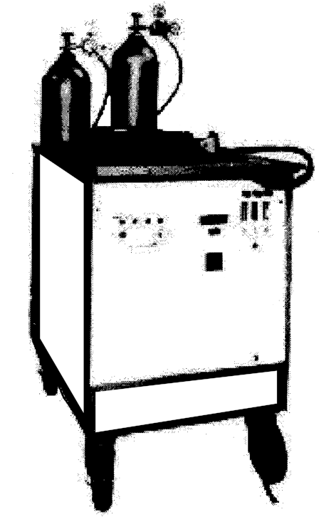
FIGURE 5 – Plasma-arc Cutting Torches
4.3.6 Using a water-cooled GTAW (gas tungsten-arc, formerly TIG) welding torch and conventional dc current with straight polarity, cutting may be done on metals to 6.4 mm (1/4 in) in thickness. For this work, 3.2 or 4 mm (1/8 or 5/32 in) diameter thoriated electrodes shall be used with gas cups no larger than 6.4 mm (1/4 in) bore. Electrode extension shall be about 6.4 mm ( 1 / in) and argon flow rates as high as 14 to 28 L/min (30 to 60 cfh). Amperage shall be approximately 300 to 350 for 6.4 mm (1/4 in) thick material, correspondingly less for thinner sections. The arc is
struck as for welding and, after the molten pool has blown through, the torch is moved along the line of projected cut at the rate of speed necessary to support cutting. In stainless steels and some other metals, dross or solidified droplets will form at the bottom edge of the cut opposite the location where the work cable is located. Thus, in many cases, the work can be positioned advantageously so that the dross forms on the piece to be scrapped.
TABLE IA – Oxyacetylene Hand Flame Cutting of Clean, Mild Steel 3.2 mm to 304.8 mm Thick, Not Preheated
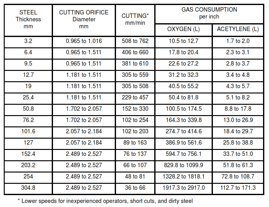
TABLE IB – Data for Oxyacetylene Hand Flame Cutting of Clean Mild Steel 1/8 inch to 12 inches Thick, Not Preheated
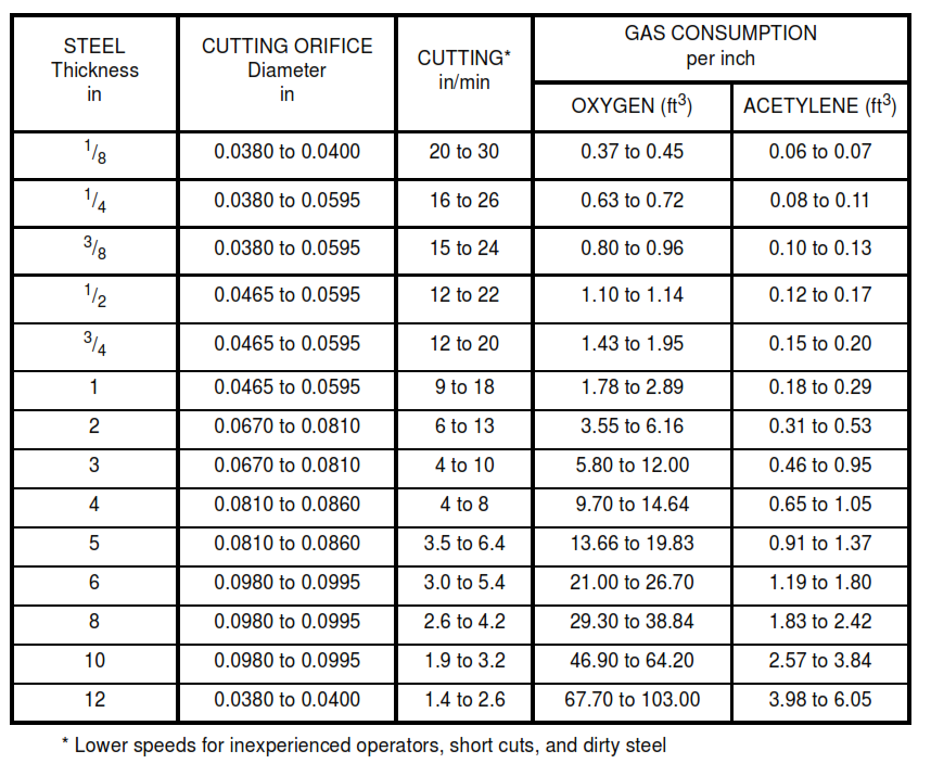
TABLE IIA – Performance Characteristics of Solid Core Electrodes for Metal-arc Cutting Steel Plates (Metric Units)
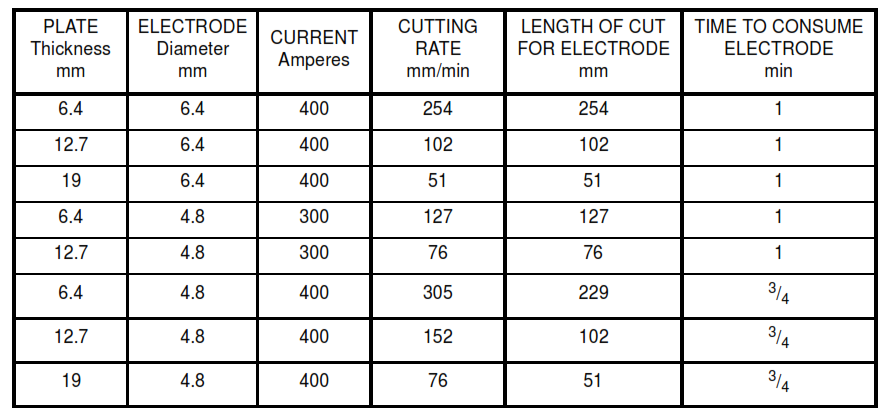
TABLE IIB – Performance Characteristics of Solid Core Electrodes for Metal-arc Cutting Steel Plates (Imperial Units)
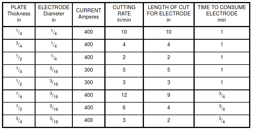
TABLE III – Copper-Clad Electrodes and Polarity
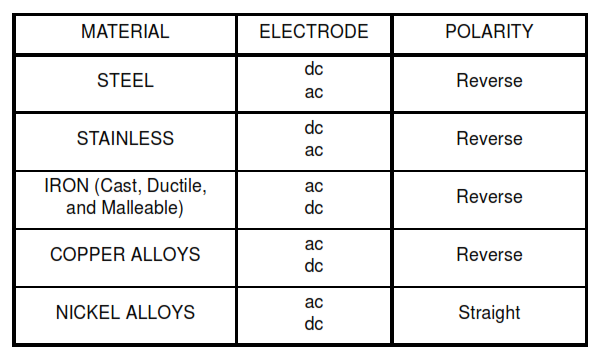
TABLE IV – Direct Current Reverse Polarity
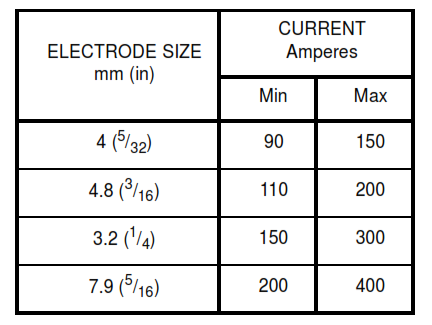
TABLE VA – Operating Conditions and Recommended Gas-Flow Rates for Plasma-Arc Cutting of Steel and Cast Iron (Metric Units)
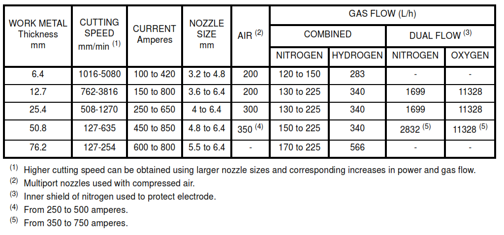
TABLE VB – Operating Conditions and Recommended Gas-Flow Rates for Plasma-Arc Cutting of Steel and Cast Iron (Imperial Units)
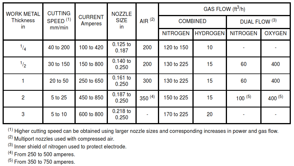
TABLE VIA – Operating Conditions and Recommended Gas-Flow Rates for Plasma-Arc Cutting of Stainless Steel and Aluminum (Metric Units)

TABLE VIB – Operating Conditions and Recommended Gas-Flow Rates for Plasma-Arc Cutting of Stainless Steel and Aluminum (Imperial Units)
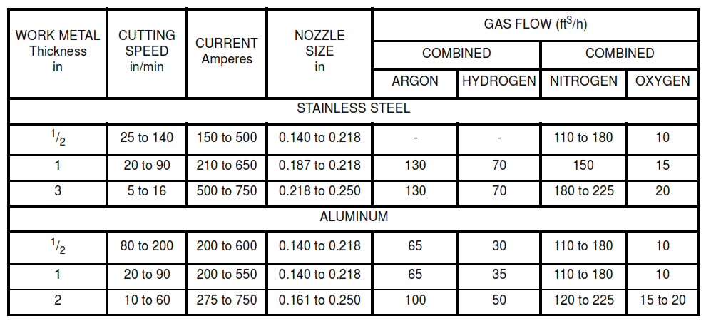
TABLE VIIA – Typical Current Levels used for Plasma-Arc Cutting of Steel, Stainless Steel, and Aluminum at Various Thicknesses

TABLE VIIB – Typical Current Levels used for Plasma-Arc Cutting of Steel, Stainless Steel, and Aluminum at Various Thicknesses (Imperial Units)
