We are discussing here Following Contents.
- SCOPE
- REFERENCES
- GENERAL
3.1 Process Description
3.2 Application
- SAFETY
- MATERIALS
- EXECUTION
6.1 Fundamentals Of Torch Brazing
- INSPECTION
- MARKING
Torch Brazing Figure
- Typical Joints
TABLE
I. Brazing Filler Metals
II. Fluxes
III. Joint Clearance (Millimeter)
Torch Brazing General Practices | Fundamentals of Torch Brazing | Applications
1. Scope
This article describes the general practices for torch brazing materials to be joined, filler metals, and fundamental techniques used in the practice of brazing.
2. References
Reference is made in this article to the following documents.
American Welding Society (AWS)
A5.8 Specification for Brazing Filler Metal
American Society of Mechanical Engineers (ASME)
Section II, (Part C) Specification for Welding Rods, Electrodes and Filler Metals
Section V Non Destructive Examinations
Section IX Welding and Brazing Qualifications
American National Standards Institute (ANSI)
Z 49.1 Safety in Welding and Cutting
3. General
3.1 Process Description
3.1.1 Brazing is a process where a nonferrous filler metal with a melting point above 450 °C (840 °F), but below that of the metal being joined, is distributed in the joint by capillary action while in a molten condition. Torch brazing is done by heating with a gas torch, or torches, usually oxyacetylene. Other fuel gas torches or electric heat guns (1000-watt rating for small parts) may also be used.
3.1.2 The process is referred to frequently as silver alloy brazing, silver brazing, or silver soldering. It is recommended that the word brazing be used since brazing alloys other than silver or silver alloys are also used.
3.1.3 There are other methods of heating such as induction, furnace, and hot dipping which are not described in this standard.
3.2 Application
3.2.1 Most metals can be brazed satisfactorily following the steps outlined in this standard. Aluminum, cast iron, copper and copper alloys, steels, stainless steels, nickel and nickel alloys, and others are brazable to themselves and frequently in combination, for example, copper to stainless steel.
3.2.2 Common uses include lap joints on tubing, sheet metal, and applications where welding would be impractical, for example, lack of accessibility or in dissimilar metal combinations.
4. Safety
4.1 Safe practices prescribed in SES W02-F01 shall be followed on plant sites.
4.2 Special consideration shall be given to provide adequate ventilation during brazing to avoid excessive inhalation of fumes given off by fluoride containing fluxes and brazing alloys containing cadmium, zinc or combination of both.
5. Materials
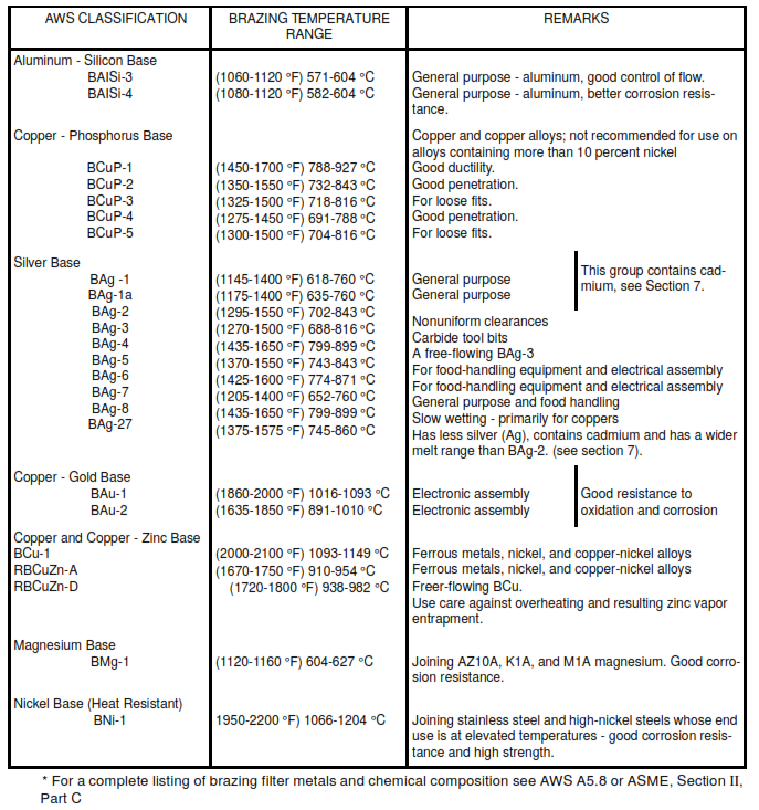
5.1 The filler metals listed in Table I shall be used for torch brazing. There are many others which are commonly used with furnace, resistance, induction, and other heating methods. Analyses and other data are given in Table I.
5.2 The selection of a brazing alloy for a specific metal or combination is based upon the end use of the assembly. Operating temperature, corrosion environment, and strength of joint should be evaluated. Adequate strength, especially shear, is obtained at room temperatures and, in general, these alloys possess good corrosion properties.
5.2.1 Actual test and experience is the best criteria for selection.
5.3 Brazing alloys are available as strip, powder, wire in coils, rod, and preformed shapes.
5.4 Anticapillary compounds or stop-off materials, are available and are used to limit the flow of the brazing alloy to the surfaces to be joined.
5.5 Fluxes are almost always used in torch brazing; copper and most brasses shall be brazed with the BCuP and BAg alloys without flux if heating cycles are short. Fluxes are not intended to remove oxides and surface contaminants, but rather to dissolve oxides and hinder their formation during heating.
6. Execution
6.1 Fundamentals of Torch Brazing
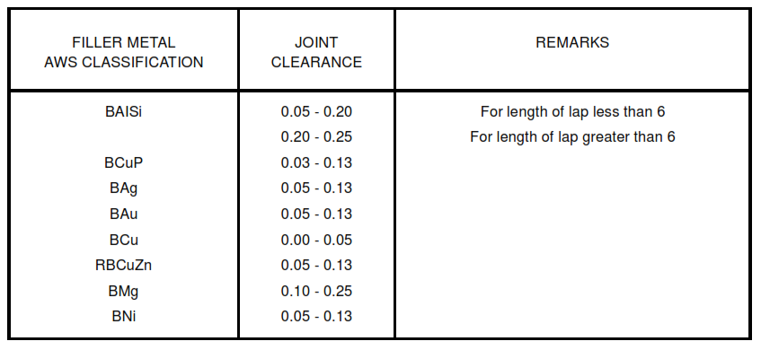
6.1.1 Fit and Clearance – Parts shall be properly fitted to be brazed. Suggested joint clearances are listed in Table III.
6.1.2 Dissimilar Metals – When joining dissimilar metals, differences in coefficients of expansion at the brazing temperature shall be considered in designing joint clearance. Dependence upon capillary force to allow the brazing alloy to flow requires maintenance of adequate clearance; in addition, maximum strengths are obtained with minimum clearance. Typical joints are shown in Figure 1.
6.1.3 Clean Metal – Remove all oil, grease, oxide, scale, and dirt from all surfaces to be brazed. The original surface condition dictates the nature and extent of cleaning. Frequently decreasing, pickling, and emery papering or filing are adequate; the object is to clean the metal to a bright finish. Joints shall be brazed as soon as possible after cleaning, and shall not be handled before brazing.
6.1.4 Fluxing – Fluxing serves to minimize oxidation during heating, absorbs residual surface oxides formed during heating, and assists in the flow of brazing alloy. Paste fluxes shall be applied uniformly to the parts to be brazed. More liberal applications are required on stainless steels than on copper; as well as on thicker pieces which will be subject to prolonged heating. Use of flux is essential when working with cadmium bearing material to prevent the generation of poisonous fumes.
6.1.5 Assembly – Parts to be brazed shall be assembled immediately after fluxing. In many instances, it shall be necessary to support the parts so the joint shall not come apart once the braze is made and while the brazing alloy is molten.
6.1.6 Heating and Flowing –
6.1.6.1 Uniform heating is mandatory. When unequal thicknesses, or metals possessing different coefficients of thermal conductivity are to be brazed, preferential heating of the thicker and higher conductivity member is required.
6.1.6.2 Avoid overheating base and filler metal as this results in excessive oxidation, excessive fumes, and poor flowing of the brazing alloy. This in turn prevents filling the joint with the filler metal. Do not direct the flame towards the filler metal, particularly if it is cadmium bearing. Heating with an oxyacetylene torch requires the use of a neutral or slightly reducing flame Raise the temperature of the parts only slightly above the melting point of the brazing alloy (or the upper limit of the brazing range shown in Table I. The inner cone shall never contact the work; a large neutral flame permits the optimum general heating. Hold the flame somewhat away from the joint and keep it in constant motion, passing over all sides until ready for flowing alloy.
6.1.6.3 When the proper temperature is reached, as indicated by total melting of flux, add a small amount of brazing alloy. If the surface is clean and hot, the alloy will “run” and “tin”, and flow into the joint. Add brazing alloy until the joint is full and reduce heating gradually by increasing the torch-to-joint distance until the alloy “sets” or solidifies.
6.1.7 Cleaning – All residual flux shall be removed. Hot water rinsing usually is adequate; wire brushing may be required at times. Frequently, “loaded” flux which has dissolved appreciable amounts of oxide is difficult to dissolve, and steaming or sandblasting may be necessary.
7. Inspection
7.1 The amount and type of inspection required depends upon the service conditions and hazards to personnel and property. It is the responsibility of the initiating maintenance or project engineer to define the inspection requirements.
7.2 It is beyond the scope of this standard to define the various types of nondestructive tests that may be required. However, dye penetrant (PT) is generally not recommended because repair is difficult when contaminated with penetrant materials.
7.3 The inspection shall conform to ASME Code, Section V and Section IX Part QB.
8. Marking
8.1 The following information shall be legibly marked and be visible from the outside of each package of brazing filler metals and shall carry the following precautionary labeling as a minimum:
CAUTION
Welding may produce fumes and gases hazardous to health. Avoid breathing these fumes and gases. Use adequate ventilation. See ANSI Z 49.1 – 1973, Safety in Welding and Cutting.
8.2 Brazing filler metal of the BAg-1, BAg-1a, BAg-2, BAg-2a, BAg-3, and BAg-27 classification shall carry the following information in addition to the label described in 8.1.
WARNING CONTAINS CADMIUM
POISONOUS FUMES MAY BE FORMED ON HEATING
Do not breathe fumes. Use only with adequate ventilation, such as fume collectors, exhaust ventilators, or air supplied respirators. See ANSI Z49.1 – 1973. Never braze without flux; always apply heat to base metal, never filler metal. If chest pain, cough, or fever develops after use, call a physician immediately.
8.3 Brazing fluxes containing fluoride shall carry the following warning label on all tags, boxes, and other containers:
CAUTION CONTAINS FLUORIDES
This flux when heated gives off fumes that may irritate eyes, nose, and throat.
(1) Avoid fumes – use only in well-ventilated spaces. (2) Avoid contact of flux with eyes or skin. (3) Do not take internally.
Figure 1 – Typical Joints
TABLE I – Brazing Filler Metals

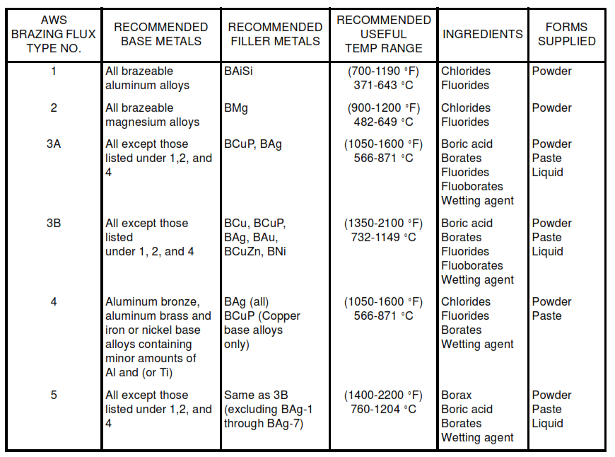
Table II – Fluxes
TABLE III – Joint Clearance (Millimeter)


