This article is about Types of Insulation Resistance Tests. Insulation resistance tests are crucial for assessing the condition of electrical insulation in various equipment and systems. These tests help identify potential issues, such as deterioration or contamination of insulation, before they lead to electrical failures or safety hazards. There are several types of insulation resistance tests, each serving a specific purpose.

Following are the main tests we included in this article:
1. Short-Time or Spot-Reading Test
The “Short-Time or Spot-Reading Test” is a straightforward method for assessing insulation resistance. Here’s an explanation of this test:
Procedure:
- Connect a Megger instrument to the insulation you want to test.
- Operate the Megger for a specific, short time period, typically around 60 seconds. You might also perform shorter tests, like 30 seconds.
- The goal is to obtain a single resistance value during this brief test.
- The resistance value obtained during this test represents a snapshot of the insulation’s condition at that moment.
- It’s important to consider factors like temperature, humidity, and the initial state of the insulation when interpreting the result.
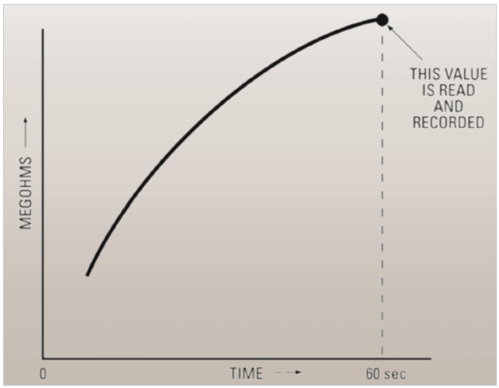
“spot-reading” test method.
Capacitance Consideration:
- For insulation with minimal capacitance, such as short house wiring runs, a spot reading test may be sufficient to gauge insulation quality.
The One-Megohm Rule:
- Maintenance professionals have traditionally used the “one-megohm rule” to set a lower limit for acceptable insulation resistance. This rule suggests that insulation resistance should be roughly one megohm for every 1,000 volts of operating voltage, with a minimum of one megohm.
- For example, a motor rated at 2,400 volts should ideally have an insulation resistance of at least 2.4 megohms.
- In practice, readings are often considerably higher than this minimum value in new equipment or when insulation is in good condition.
Periodic Testing and Trend Analysis:
- To better assess insulation condition, it’s advisable to take periodic readings and keep records.
- Persistent trends, such as a consistent decrease in insulation resistance over time, often indicate potential issues, even if the readings remain above the recommended minimum values.
- Conversely, if your periodic readings show consistency, they may be acceptable even if they are slightly below the suggested minimum values.
Typical Behavior of Insulation Resistance:
Figure below illustrates the typical behavior of insulation resistance under various plant operating conditions. These curves were generated from spot readings obtained over months using a Megger instrument.
This method provides a quick assessment of insulation quality but should be complemented with periodic readings and trend analysis to ensure the reliability and safety of electrical equipment. Persistent downward trends are typically an early warning sign of potential issues.
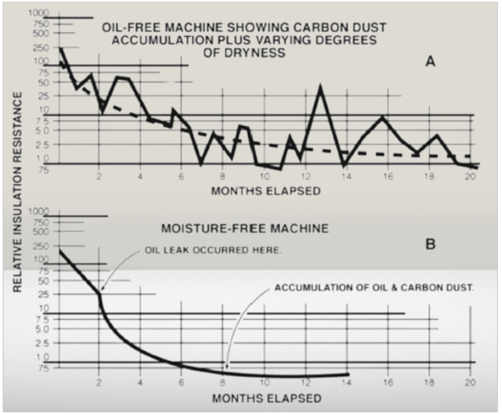
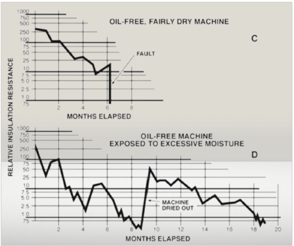
conditions, (curves plotted from spot readings with a Megger instrument).
2. Time-Resistance Method
The “Time-Resistance Method” is another approach to testing insulation resistance, and it offers certain advantages. Here’s an explanation of this method:
The Time-Resistance Method focuses on the absorption effect of insulation. It is based on the principle that good insulation exhibits a gradual increase in resistance over time due to absorption currents.
Independence from Temperature:
One notable advantage of this method is its relative independence from temperature variations. Unlike some other tests, the time-resistance method can provide conclusive information even without a history of past tests or extensive temperature correction.
- To perform this test, you take successive resistance readings at specific time intervals, typically over a duration of 5 to 10 minutes.
- These readings can reveal how the insulation behaves over time and are often referred to as “absorption tests.”
Behavior of Good Insulation:
In the case of good insulation, you will observe a steady increase in resistance (reduced current) over the testing period. This increase is primarily due to absorption currents and occurs over a much longer time frame than it takes to charge the insulation’s capacitance.
Masking Effect of Moisture or Contaminants:
When insulation contains excessive moisture or contaminants, the absorption effect is often masked by a high, relatively constant leakage current. This persistent leakage current keeps the resistance reading low (recall Ohm’s Law: R = E/I).
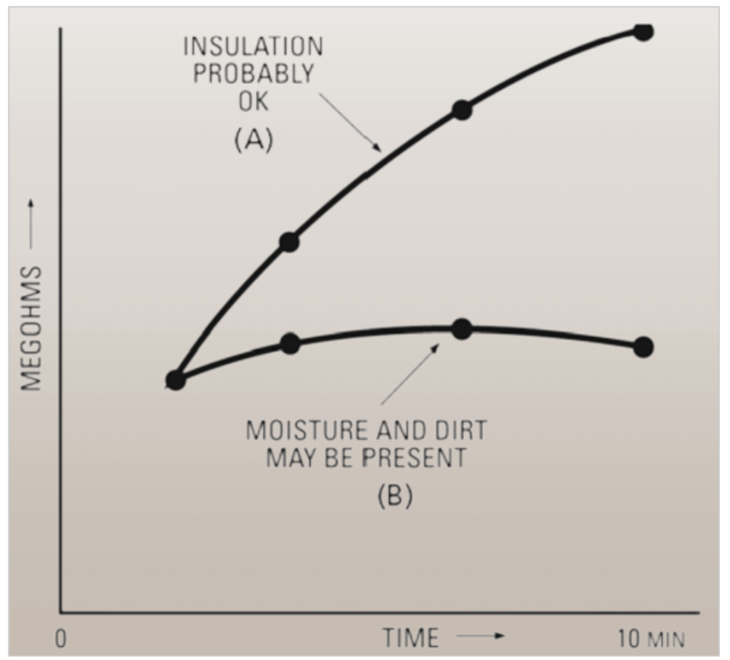
capacitive equipment such as a large motor winding.
Equipment Size Independence:
The beauty of the time-resistance test is that it is equipment-size-independent. Whether you’re testing a small motor or a large one, the increase in resistance for clean and dry insulation follows the same pattern.
Comparing and Establishing Standards:
This method allows for easy comparison between different pieces of equipment and can be used to establish standards for new equipment, regardless of their horsepower ratings.
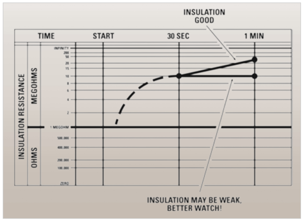
Double-Reading Test:
- A variation of this method is the “double-reading test.” In this test, you take readings at specific time intervals, such as 30 seconds and 60 seconds.
- A steady increase in resistance between these intervals indicates healthy insulation.
- Conversely, if there is no significant increase, it could suggest the presence of dirt or moisture in the windings, which requires further attention.
Equipment Requirements:
For large rotating electrical machinery with high operating voltages, conducting time-resistance tests effectively may require specialized equipment, such as a heavy-duty line-operated Megger test set, with high insulation resistance ranges and a stable test voltage.
This method provides valuable insights into the condition of insulation and can help identify potential issues with moisture or contaminants, making it a useful tool for maintenance professionals.
3. Dielectric Absorption Ratio and Polarization Index
The “Dielectric Absorption Ratio” and the “Polarization Index” are important parameters used in insulation resistance testing. Here’s an explanation of these concepts and their significance:
Dielectric Absorption Ratio:
- The Dielectric Absorption Ratio is a measure of how the insulation behaves over time. It is calculated by dividing two time-resistance readings. Typically, this ratio is expressed as a 60-second reading divided by a 30-second reading.
- This ratio is useful in recording information about the insulation’s condition and how it changes over a short duration. It provides insights into the insulation’s ability to absorb and retain an electric charge.
- A high Dielectric Absorption Ratio suggests good insulation with the ability to absorb and hold a charge over time.
Polarization Index (PI):
- The Polarization Index is a variation of the Dielectric Absorption Ratio. It is calculated by dividing a longer time-resistance reading by a shorter one. The standard calculation involves a 10-minute reading divided by a 1-minute reading.
- The PI is especially valuable for assessing insulation condition over an extended period. It reflects the insulation’s ability to maintain its resistance as time progresses.
- A high PI indicates healthy insulation that can maintain its resistance for an extended period, signifying good insulation quality.
Instrument Type and Test Duration:
- The choice of whether to calculate the Dielectric Absorption Ratio or the Polarization Index depends on the type of insulation resistance tester being used and the test duration.
- With hand-cranked Megger instruments, it is more practical to perform a 60-second test with the first reading taken at 30 seconds, leading to the Dielectric Absorption Ratio.
- For line-operated Megger instruments, it is advisable to conduct a 10-minute test and take readings at 1 and 10 minutes to calculate the Polarization Index.
Interpreting the Values:
- Both the Dielectric Absorption Ratio and the Polarization Index provide valuable information about insulation condition. High values indicate good insulation quality, while lower values may suggest potential issues.
- A significant drop in the Dielectric Absorption Ratio or the Polarization Index over time can be indicative of deteriorating insulation. Monitoring these values through periodic testing helps identify insulation problems before they lead to equipment failure.
Table below likely provides guidelines or reference values for interpreting the Dielectric Absorption Ratio or Polarization Index in relation to insulation condition. These values can serve as a reference point for assessing the health of insulation based on the calculated ratios.
In summary, both the Dielectric Absorption Ratio and the Polarization Index are essential tools in insulation resistance testing. They offer insights into the insulation’s ability to maintain resistance over time, helping maintenance professionals assess and monitor the condition of electrical insulation and identify potential issues before they become critical.
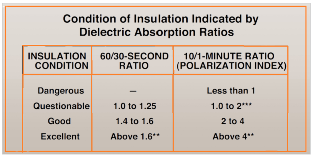
Following are important considerations when interpreting the values of the Dielectric Absorption Ratio (DAR) and the Polarization Index (PI) during insulation resistance testing. Let’s break down these notes for clarity:
Tentative and Relative Values:
- The values calculated for DAR and PI should be viewed as tentative and relative. This means that while these ratios provide valuable information about insulation condition, they should be considered in the context of experience gained through the time-resistance method over a period of time.
- In other words, these values become more meaningful and actionable as you accumulate data and experience with the specific equipment you are testing. It’s essential to establish a baseline and track changes in DAR and PI readings over time to identify trends or anomalies.
Higher Values for Dry, Brittle Windings:
- For certain types of equipment like motors, DAR and PI values that are approximately 20% higher than the standard reference values may indicate dry and brittle windings.
- Dry and brittle windings are more susceptible to damage under shock conditions or during starts. To prevent potential failures, maintenance should involve cleaning, treating, and drying the motor winding to restore flexibility and improve insulation condition.
Satisfactory Results for Low Capacitance Equipment:
- The provided reference values for DAR and PI are suitable for equipment with low capacitance, such as short runs of house wiring.
- Equipment with low capacitance typically exhibits faster changes in insulation resistance, and the reference values are adjusted accordingly to reflect this behavior.
While DAR and PI values serve as valuable indicators of insulation condition, their interpretation should be context-specific and consider the type of equipment being tested. Experience and historical data play a crucial role in determining whether the calculated values fall within an acceptable range or signal potential issues with the insulation. Additionally, adjustments may be necessary for equipment with specific characteristics, such as dry and brittle windings in motors.
FAQs:
Q1: What is the purpose of a Short-Time or Spot-Reading Test in insulation resistance testing?
Q2: When is a Time-Resistance Test typically used in insulation testing, and what does it reveal about insulation condition?
Q3: What is the primary purpose of a Step Voltage Test in insulation resistance testing, and when is it most beneficial?
Q4: How does the Dielectric Absorption Ratio (DAR) Test differ from other insulation resistance tests, and what insights does it provide?
Q5: What does the Polarization Index (PI) Test measure, and how is it related to the DAR Test?
Q6: In what scenarios is a Step Voltage with PI Test employed, and how does it enhance insulation testing?
Q7: Are there recommended minimum insulation resistance values for equipment, and how do they relate to different types of tests?
Related Articles:
What is Good insulation?
What Makes Insulation Go Bad?
How Insulation Resistance is Measured.
How to Interpret Resistance Readings.
Factors Affecting Insulation Resistance Readings.
Test Voltage vs. Equipment Rating.
AC Testing vs. DC.
Use of DC Dielectric Test Set.
Tests During Drying out of Equipment.
Effect of Temperature on insulation Resistance.
Effects of humidity.
Preparation of Apparatus to test.
Safety Precautions.
Connections for testing insulation resistance of electrical equipment.
Additional Notes About using A Megger Insulation Tester.
Interpretation-Minimum Values.
Minimum Values for Insulation Resistance.
Tests Using Multi-Voltage Megger Insulation Testers.
Step-Voltage Method.
Use of a Guard Terminal.
Outdoor Oil Circuit Breaker.