This article is about application, advantages, and precautions to be observed in the use of ultrasonic flowmeters. Main keywords for this article are Ultrasonic Flowmeters Design Requirement. Time of Flight Flowmeter. Doppler Flowmeter. Time of Flight Flowmeter Applications. Doppler Flowmeter Applications, Ultrasonic Flowmeter Advantages, Ultrasonic Flowmeters Precautions, Doppler Flowmeter Precautions.
Reference is made in this standard to the following documents.
Flow Measurement PIP PCCFL001.
Ultrasonic Flowmeters Design Requirement
- The ultrasonic flowmeter is a special application device which shall only be used where conditions preclude the use of other metering methods. For the majority of applications, alternate methods will provide better accuracy at lower cost. The magnetic flowmeter, for example, is an alternative nonintrusive device which in many instances could perform the same service at lower cost.
- Time of flight, and Doppler type ultrasonic flowmeters covered in this article measure liquid velocity in a pipeline without intruding into the flowstream.
Time of Flight Flowmeter
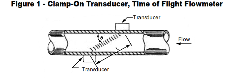
The Time of Flight flowmeter employs two transducers either clamped to or mounted in the walls of a flow section (wetted). They are usually set at a 45° angle to the direction of flow. See Figures 1 and 2.
- Each transducer acts as both a transmitter and receiver of ultrasonic pulses. Transmissions against the flow take longer to reach their destination than those sent in the direction of flow. This causes a difference in apparent frequency for the two received transmissions which is directly proportional to the average velocity of liquid in the pipe. The relationship can be expressed as follows:
∇f = 2V cos Ø/L (1)
where
∇f = Frequency difference
V = Average liquid velocity
Ø= Angle of sonic path with respect to pipe wall
L = Distance between transducers - The speed of sound is not a factor in the equation, so temperature, density, viscosity, and pressure changes have no effect on calibration except to the degree that they
alter the distance between transducers (L). - Transducers for small (<1/2 in) pipe sizes can be mounted axially in a U-bend flow configuration.
- The principle of operation is identical to the larger meters. Since cosØ now equals 1, the flow equation becomes
∇f = 2V / L (2)
Doppler Flowmeter
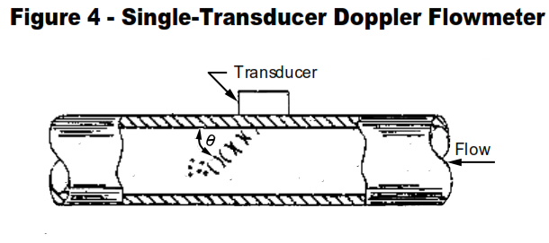
- Doppler flowmeters usually employ a single transducer mounted on the outside wall of a pipe section. Ultrasonic pulses transmitted at an angle (typically 45°) to the flow are reflected back to the transducer from solids or entrained gases in the stream (Figure 4).
- The reflected signal exhibits a Doppler frequency shift directly proportional to the velocity of the moving reflectors. The relationship is defined by:
∇f = 2ft V cos Ø/C (3)
where
∇f = Frequency difference
ft= Transmitted frequency
V = Velocity of moving reflectors
Ø = Angle of sonic path with respect to pipe wall
C = Velocity of sound in the medium coupling the sonic beam to the pipe wall
- Ideally, the transmitted frequency penetrates the full diameter of the flowing medium with the reflected velocity signals being averaged. This produces a representative average velocity reading. The degree to which full penetration is actually achieved varies with model and application. Poor penetration produces erroneously low readings.
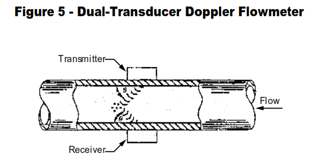
- A variation of the Doppler design employs two radially mounted transducers: one transmitting and one receiving (Figure 5).
- Ultrasonic pulses from the transmitter are reflected to the receiver by solids or entrained gas in the stream. The relationship between velocity and Doppler frequency shift is the same as described above.
Time of Flight Flowmeter Applications
- Time of Flight Flowmeter requires a liquid flowing medium which is sound conductive and relatively free of suspended solids or entrained gas.
- Available standard models measure velocities between 0.1 and 100 fps in pipe sizes 1 / 4 inch and above.
- Manufacturers claim accuracies of 0.5 percent of full scale or 0.5 to 1.5 percent of rate. Past data, however, indicates these are optimistic.
- Liquid temperature limits for standard meters are -18 to +260 ºC (-0.4 to +500 ºF) depending upon model and transducer location. Meters for temperatures to -200 ºC (328 °F) are also available. Above 260 ºC (500 ºF) the transducer crystals lose efficiency as they approach their Curie points.
- Maximum ambient temperature, depending upon model, is 50° to 6 °C (122 to 140 °F). Minimum ambient temperature is -60 °C (-76 °F) but below 0 °C (32 °F) a heating element shall be included in the case.
- Pressure drop across the straight-through meter is zero. For smaller meters using the U design, the drop is equivalent to two 90° elbows. Two additional 90° elbows are required if the meter is installed in a straight pipe section.
- Liquid pressure limits using through-wall transducers range from 300 to 3000 psig depending upon model and pipe size. Clamp-on transducers are limited only by the pressure rating of the pipe.
- Through-wall transducers are preferable to clamp-on because of more precise positioning and better signal-to-noise ratios. However, there is the potential of corrosion and seal leakage, which shall be considered when specifying.
- The meter shall always be flooded when in operation. A partially filled meter will indicate zero output if the ultrasonic path between transducers is broken.
Doppler Flowmeter Applications
- The Doppler flowmeter requires a liquid flowing medium containing significant quantities of suspended solids or entrained gas. Readings using entrained gas are not reliable unless the degree of entrainment is closely controlled. Solids concentration requirements vary depending upon particle size and characteristics. In general, the meter will operate over a range of 0.5 to 20 percent by volume. At higher concentrations the ultrasonic transmissions cannot adequately penetrate the liquid. Only echoes along the near pipe wall are received, and as flow along the wall is lower than in the center of the pipe, the readings are several percent lower.
- Several high frequency Doppler flowmeters are claimed to operate at extremely low solids concentrations. SABIC has no experience to either prove or disprove these claims.
- Doppler flowmeters employing radially mounted transducers will not in theory give false readings resulting from high solids concentration. When the receiver fails to detect a signal, the meter indicates no flow.
- Standard model spans range from 0-4 fps to 0-40 fps for pipe diameters of 1 to 8 inches. Meters suitable for pipe size up to 80 inches are typical. The minimum detectable velocity is approximately 0.25 fps. Below 3 fps, readings tend to be low because of gravity effects upon the reflecting particles.
- Specified accuracies are typically 2 percent of span. Engineering Test Center (ETC) tests made in 1981 indicate that under laboratory conditions, errors of 2 to 5 percent of span are achievable. However, in a typical plant application, errors up to 20 percent of span can be expected. These meters offer perhaps the lowest accuracy of any major class of flowmeter.
- Liquid temperature limits are -23 to +120 ºC (-9 to 248 ºF) depending upon the model.
- Maximum ambient temperature for most models is 60 ºC (140 ºF). Minimum ambient temperatures range from -23 to 0 °C (-9 to 32 °F).
- Transducer location shall be carefully selected. Placement downstream of a turbulence-producing device, for example a valve, elbow, orifice plate, or pump can give totally erroneous readings. The ideal position about the circumference of a horizontal pipe is at the side (9 or 3 o’clock). This avoids errors caused by sediment along the bottom of the pipe, or air pockets along the top.
Ultrasonic Flowmeter Advantages
- The ultrasonic flowmeter places no obstructions in the flowstream. This permits its use with liquids whose corrosiveness, abrasiveness, or viscosity render other metering methods impractical.
- There are no mechanical parts to wear out.
- Defective transducers in clamp-on designs can be replaced without interrupting flow. While special designs have been made which permit replacement of wetted transducers without interrupting flow, removal normally requires shutting down the lines.
Ultrasonic Flowmeters Precautions
- Time of Flight Flowmeter
- The Time of Flight flowmeter is relatively expensive in smaller pipe sizes and has a limited application history.
- Electronics in the meter are relatively sophisticated and may require manufacturer rather than site repair.
- Operation in flow streams with small amounts of solids or entrained gas is not predictable. In previously untried applications the meter should be purchased on a trial basis.
- A small percentage of liquids have acoustical properties which do not permit ultrasonic metering. When requested, most manufacturers will test a sample of a questionable liquid.
Doppler Flowmeter Precautions
- Doppler flowmeter is sometimes claimed, erroneously, to be a universal portable flowmeter. It will operate properly only where levels of solids suspension or gas entrainment are suitable. Under other conditions, it may appear to be functioning, but give indications grossly in error. Previous knowledge of the approximate flowrate it is required to check that the meter is functioning correctly. Some vendors state that for satisfactory operation the solid concentration should be above 25 ppm and the size of the solid or gas bubbles should be 30 microns or larger.
- In multiple installations, Doppler meters can interact. This is particularly true if the same transmitting frequencies are used. Thirty feet or more between installations is typically recommended.
- The clamp-on meter is not recommended when the pipe wall is not homogeneous, for example lined pipe or pipe with sonically opaque coatings.


