Megger insulation testers, especially those with ranges of 1000 megohms and higher, come equipped with a valuable feature known as the Guard terminal. This terminal serves a dual purpose: first, it facilitates the creation of a three-terminal network for making specific resistance measurements, and second, it provides a regulated DC voltage source with limited current capacity.
Guard Terminal in Insulation Testing
Let’s delve into the details of how the Guard terminal is employed:
1. Three-Terminal Network:
Electrical apparatus insulation has two primary conducting paths – one through the insulating material and the other along its surfaces. The Guard terminal introduces a third test terminal into the surface leakage path, effectively splitting it into two sections, thus forming a three-terminal network. This network allows for precise measurements of specific resistance values within the apparatus.
2. Practical Applications:
The Guard terminal can be applied in various scenarios. In some cases, such as with single conductors or exposed insulation, a three-terminal network takes the form shown in below Figure 1a. Other situations, like two-winding transformers or multi-conductor cables, require a different configuration, as illustrated in below Figure 1b.

3. Making Measurements:
To perform a three-terminal test and obtain a single resistance measurement (e.g., r12), you connect the Line terminal of the Megger instrument to Terminal 1, the Guard terminal to Terminal 3, and the Earth terminal to Terminal 2 (as shown in Figure 1a). This setup provides the accurate value of r12, assuming that r23 and r13 are not too low in resistance. For proper operation, r23 should be approximately 1 megohm or higher to avoid overloading the generator and maintaining stable generator voltage. Additionally, r13, which shunts the Megger deflecting coil, should be at least 100 megohms for an accuracy of about 1%.
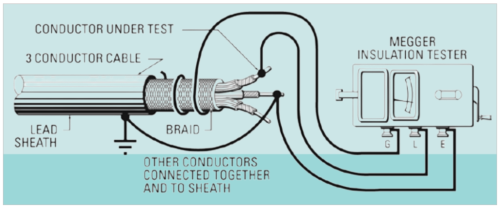
Figure 2 below demonstrates how the Guard terminal in Megger insulation testers can be employed to eliminate the effects of surface leakage across exposed insulation at one end of a cable. This technique is particularly valuable when assessing the insulation resistance of a cable or conductor while ensuring that any surface leakage currents do not interfere with the measurement.
4. Ensuring Safety:
When using the Guard terminal, especially with motor-driven or rectifier-operated Megger instruments, it’s crucial to prevent any potential arc-over between the guarded terminal of the sample and ground. Arcing could lead to undesirable consequences, including damage to the instrument’s generator commutator.
Figure below provides a visual representation of how the Guard connection in Megger insulation testers can be employed to eliminate the effects of surface leakage across exposed insulation at both ends of a cable. This configuration is particularly useful when a spare conductor within the cable is available for establishing the Guard connection.
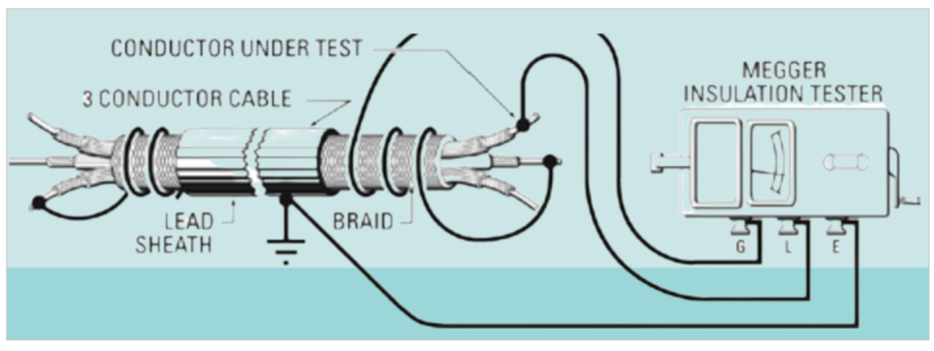
Figure below illustrates how the Guard connection in Megger insulation testers can be effectively employed to eliminate the effects of leakage to both ground and adjacent conductors. This configuration extends the concept presented in Figure 2, where the Guard connection was utilized to eliminate surface leakage across exposed insulation.
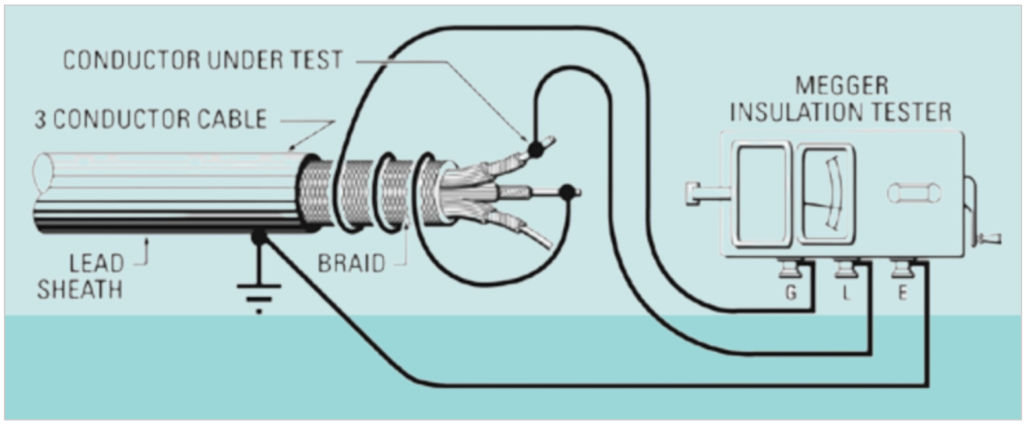
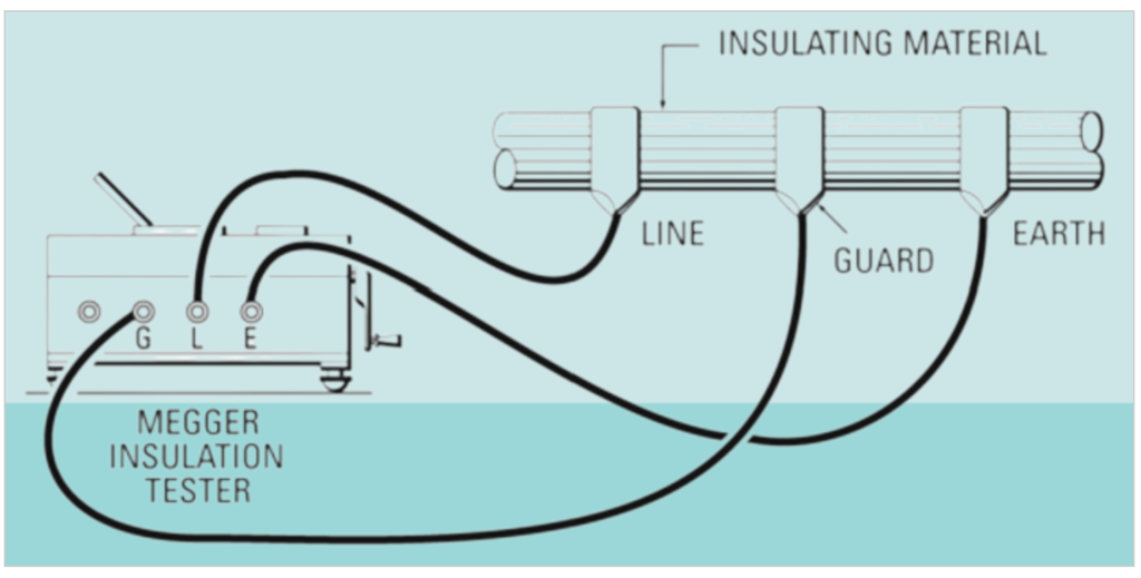
Figure below illustrates a setup that employs the Guard connection in a Megger insulation tester to eliminate the effects of surface leakage when measuring the true resistance of an insulating member, such as a lift rod in a circuit breaker. This configuration ensures accurate measurement of the insulating member’s resistance without interference from surface leakage currents.
5. Calculating Accurate Measurements:
In cases where precise resistance values for each leg are required, typically when dealing with configurations like that in Figure 1b, three separate measurements are needed. To calculate these values accurately, use the following equations:
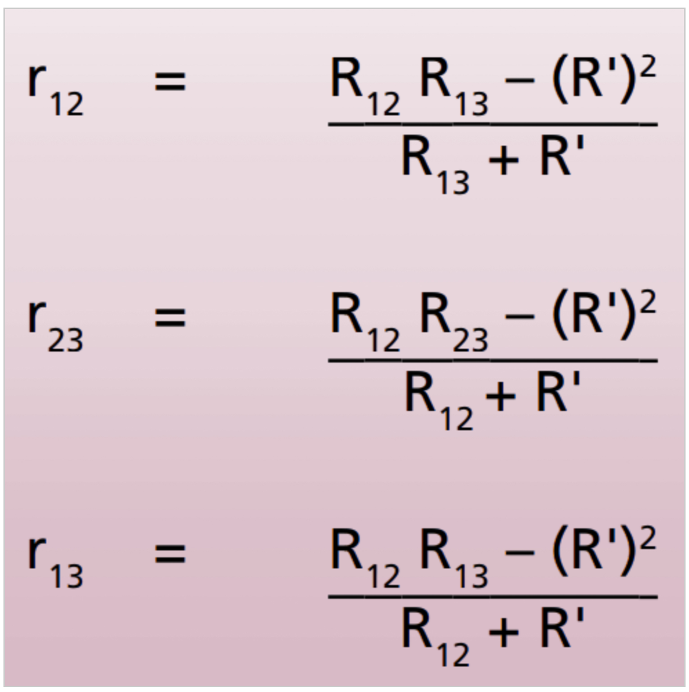
Here, R12, R23, and R13 are the actual readings in megohms measured across the terminals connected to the Line and Earth terminals of the Megger instrument, with Terminals 3, 1, and 2 linked to the instrument’s Guard terminal. R’ represents the value of the ballast resistance in megohms specific to the instrument in use.
6. Avoiding Leakage:
When conducting these three measurements, refrain from connecting the Line terminal of the instrument to the grounded terminal of the network. This prevents any leakage over the instrument case between the Earth terminal and ground, which could inadvertently affect the resistance being measured.
Understanding and utilizing the Guard terminal in Megger insulation testers is essential for accurate and meaningful insulation resistance measurements in various electrical apparatus and equipment.
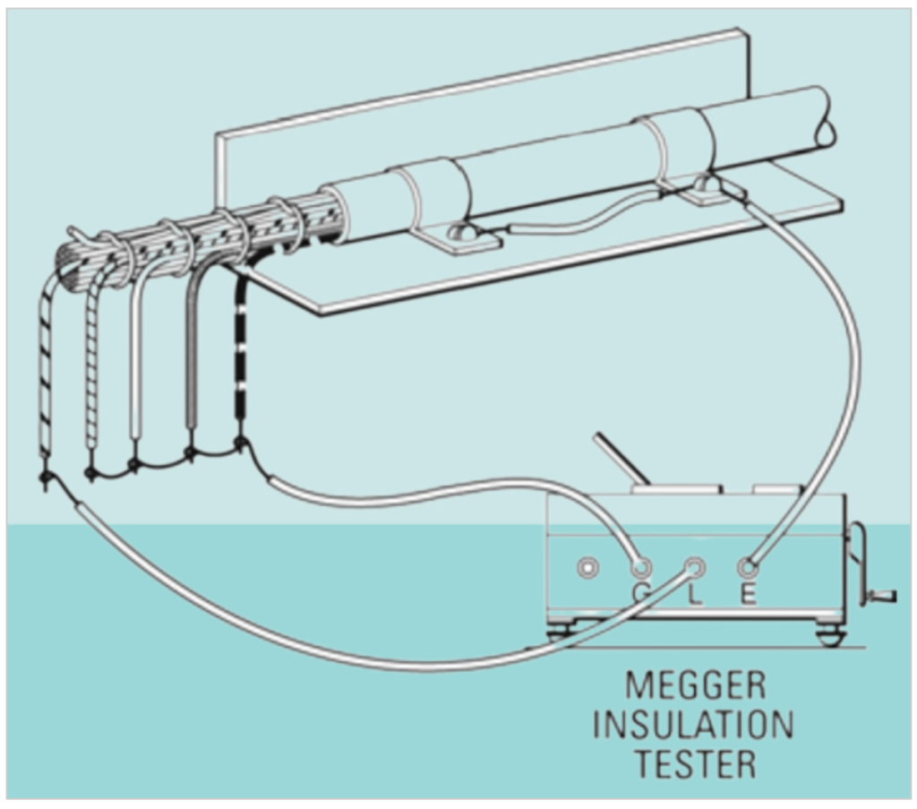
Below figure illustrates a specific configuration for testing the insulation resistance between one wire and ground while ensuring that leakage to other wires does not affect the measurement. This setup is commonly used in electrical testing to isolate the wire of interest and obtain accurate measurements.
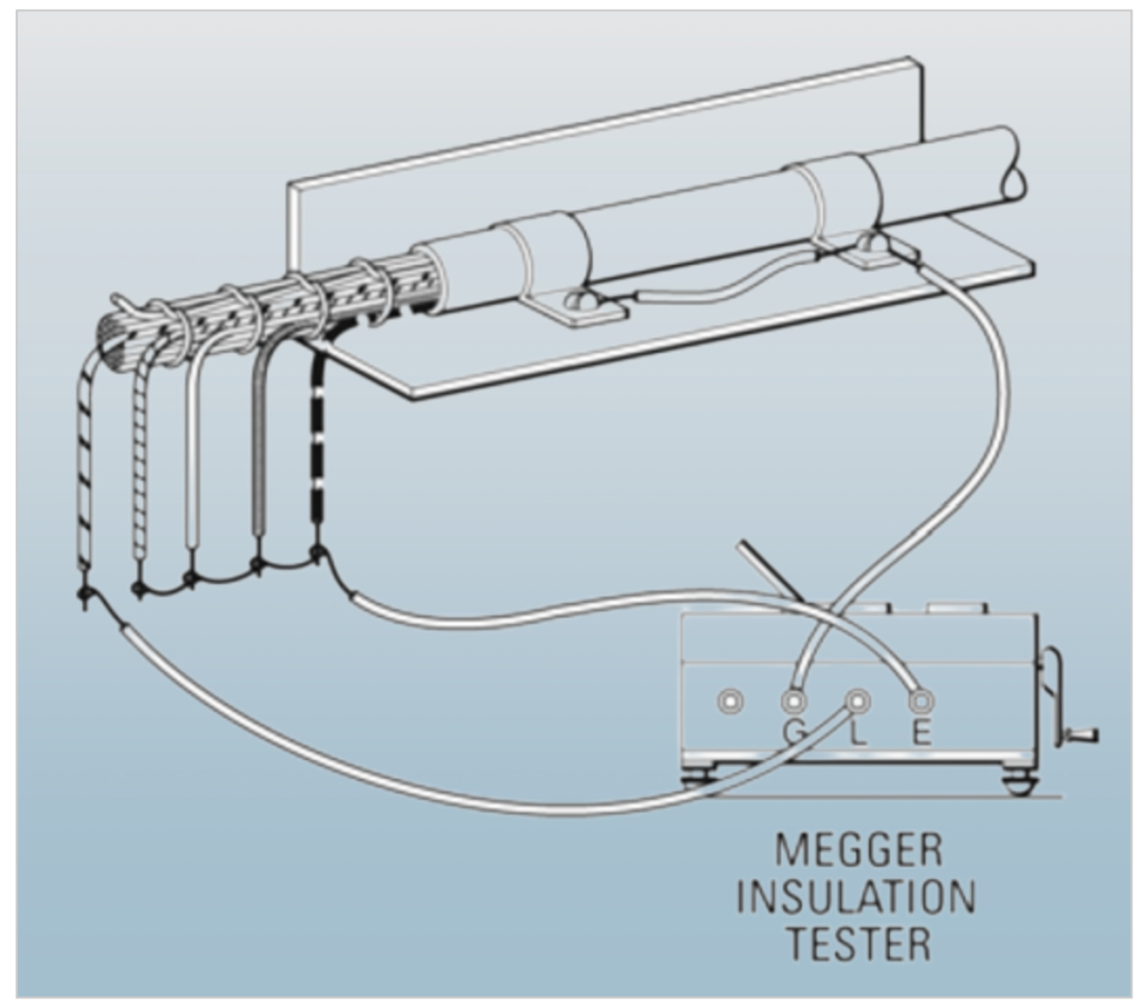
Below Figure illustrates a specific configuration for testing insulation resistance between one wire and all other wires connected, all while preventing the effects of leakage to ground. This setup is commonly used in electrical testing to isolate the wire of interest and ensure accurate measurements.
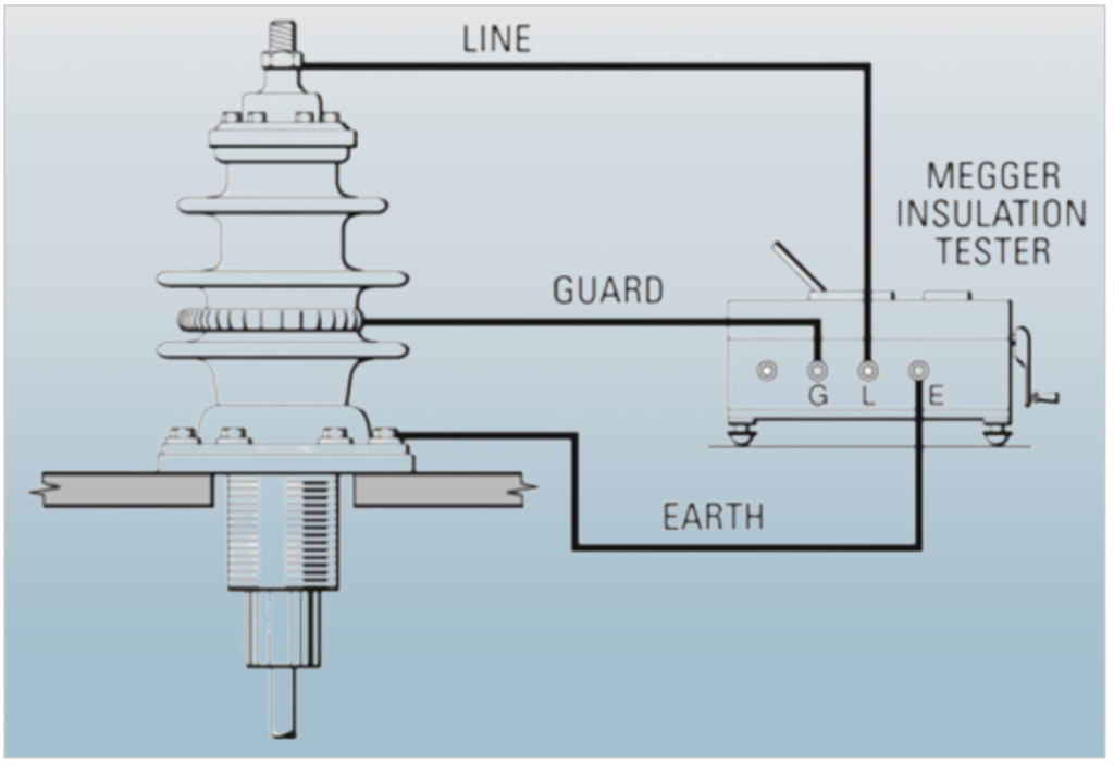
Below Figure illustrates the use of a spring collar as a Guard connection to eliminate the effects of surface leakage when performing insulation resistance testing. This setup is designed to ensure accurate measurements by preventing surface leakage currents from affecting the results.
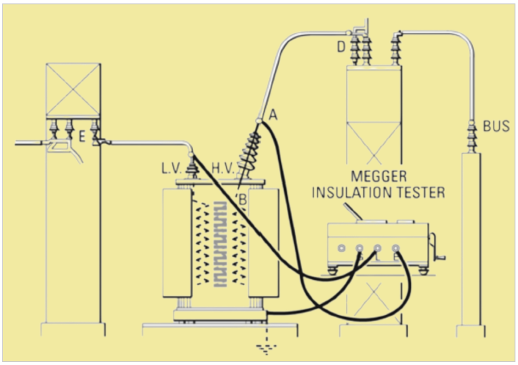
Below Figure illustrates the connections required for testing the insulation resistance between high and low voltage windings in electrical equipment without being affected by leakage to ground. This type of test is crucial for ensuring the integrity and safety of such equipment.
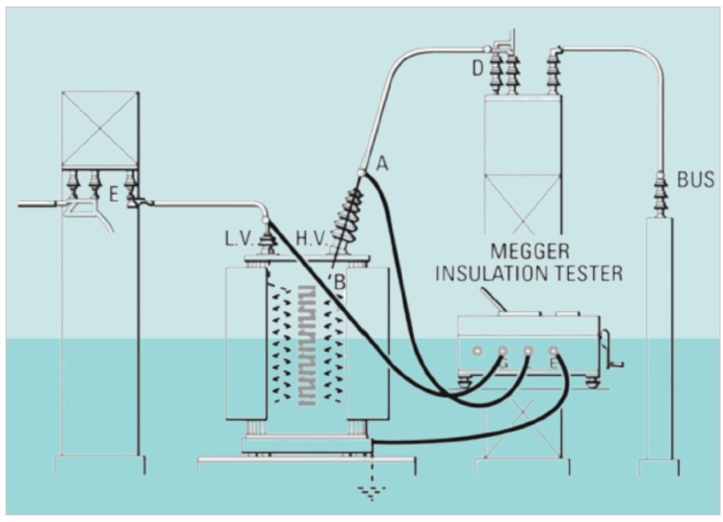
Below figure outlines the necessary connections for conducting insulation resistance tests between high and low voltage windings in electrical equipment. This ensures the safety and reliability of the equipment by identifying any insulation weaknesses between these critical components.
Related Articles:
What is Good insulation?
What Makes Insulation Go Bad?
How Insulation Resistance is Measured.
How to Interpret Resistance Readings.
Factors Affecting Insulation Resistance Readings.
Types of Insulation Resistance Tests.
Test Voltage vs. Equipment Rating.
AC Testing vs. DC.
Use of DC Dielectric Test Set.
Tests During Drying out of Equipment.
Effect of Temperature on insulation Resistance.
Effects of humidity.
Preparation of Apparatus to test.
Safety Precautions.
Connections for testing insulation resistance of electrical equipment.
Additional Notes About using A Megger Insulation Tester.
Interpretation-Minimum Values.
Minimum Values for Insulation Resistance.
Tests Using Multi-Voltage Megger Insulation Testers.
Step-Voltage Method.
Outdoor Oil Circuit Breaker.