This article is about UPS Transfer Switch Material Selection Criteria & Checklist & Requirements of Electrical Power System as per International Codes and standards for Commercial Buildings, Plants and Refinery Projects.
UPS Transfer Switch Material Selection Criteria & Checklist
QC Before Installation- Transfer Switch shall conform to all applicable requirements, standards, and specifications prior to release to be used as part of work.
Incoming Transfer Switch shall be visually inspected for damage / defects occurred during transportation and conformance to all applicable requirements..
Transfer Switch shall be new and unused.
Transfer Switch shall be in accordance with the Saudi Aramco-approved project-specific design drawings, diagrams, schedules, lists, databases, and associated design documents.
Check that the Contractor or it’s Saudi Aramco approved third party inspector performed the quality activities at the supplier and sub-supplier locations as required by the inspection level assigned for the materials and equipment identified in SAER-1972 Inspection Requirements.
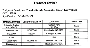
Acceptable Manufacturers – The list of acceptable manufacturers of transfer switches shall be as shown below:
As Designed – Transfer switch and accessories shall be in accordance with the Saudi Aramco-approved project-specific design drawings, diagrams, schedules, lists, databases, and associated documents.
As Designed – Transfer switch configuration and ratings (i.e., voltage, current and the number of phases for which they are designed) shall match the electrical system.
As Designed – Transfer switch short-circuit and interrupting ratings shall exceed the available fault current from the system (as calculated).
Transfer switch shall only be used in low voltage applications.
Transfer switch shall not be used as a substitute for a secondary-selective substation.
If used for emergency applications, transfer switches shall be automatic and shall be specified to have overlapping neutral contacts and maintenance bypass switches.
Closed-transition transfer switches shall not be used.
Transfer switch shall be fully withdrawable, if it feeds a controlgear. (SAES-P-116, Sec. 10.2.1 (b))
Transfer switch shall be third-party tested, and listed or labeled as manufactured per NEMA ICS 10 and comply with the requirements of UL 1008.
Transfer switch shall be third-party tested, and listed or labeled as manufactured per IEC 60947-6-1.
Transfer switches built utilizing a mixture of Standards (e.g., devices only tested and rated by IEC within a NEMA tested and rated controlgear assembly) is unacceptable.
When the term “transfer switch” is used it includes all associated equipment such as bypass and isolation switches, control equipment, etc.
Transfer switch shall be rated for continuous duty.
Transfer switch short circuit interrupting rating shall be minimum 10 kA rms.
“Transfer switch shall be suitable for continuous operation under ambient air temperature of:
a) A maximum of 40 degrees.
b) A minimum of 0 degrees.
c) Average temperature, measured over a period of 1 month, is a maximum of 30 degrees.”
“Transfer switch shall be suitable for continuous operation under average humidity :
a) For a period of 24 hours, does not exceed 95%.
b) For a period of 1 month, does not exceed 90%.”
Transfer switch shall be suitable for continuous operation at an altitude less than 1000 meters, unless a higher altitude is specified.
Enclosures shall be front accessible, deadfront, completely enclosed, and free standing.
Space heaters shall not be installed within the transfer switch enclosure.
“All conductors shall be copper, silver or alloys of these materials, with the following exceptions:
1. Parts which are internal to a pre-manufactured device (e.g., internals of circuit breaker).
2. Connectors supplied as integral parts or components of manufactured equipment such as molded case circuit breakers provided the connectors are approved for copper conductors.
3. Plating of the copper, silver or copper/silver alloy base conductor material is acceptable.”
Bus bar mating surfaces shall be either silver or tin plated.
If a neutral has been specified, a neutral conductor system shall be provided which can continuously carry the same current as the phase conductors without exceeding the temperature rise limitations.
A bypass switch shall shunt the service around the transfer switch without interrupting power to the load.
A bypass switch shall allow the transfer switch to be electrically tested and operated without interrupting power to the load.
A bypass switch shall electrically isolate the transfer switch from both sources of power and the load conductors to permit inspections and maintenance. Under this condition, the transfer switch should be able to be worked on at a detailed level with no danger of contacting electrically energized parts.
While the transfer switch is electrically isolated as described above, the transfer switch shall be operable manually.
“The transfer switch shall be equipped with voltage indication meeting the following requirements:
1. Shall give an indication on all three phases of the line side of both the primary and alternate power source.
2. Metering device shall operate at a maximum voltage of 120 VAC.”
“The transfer switch shall be equipped with amperage indication meeting the following requirement
1. Shall give an indication on at least one phase of the main circuit of the load side of the transfer switch.
2. Metering devices shall operate at a maximum current of 25 A.”
White nameplates with black lettering shall be provided to identify the panelboard with the tag number indicated within Data Schedule 1.
The Manufacturer’s shop order number, date, and catalog designation should be indicated on the controlgear nameplate in addition to the nameplate information required by the Standards indicated within the Supplement.
“Transfer switches shall be classified as Type A or Type B as follows:
Type A (PC*): A transfer switch that is not intended to provide required overcurrent (overload and short-circuit) protection.
Type B (CB*): A transfer switch that is intended to automatically provide required overcurrent (overload and short-circuit) protection.
(NEMA ICS10, P-1, Sec 3)”
The system voltage rating of transfer switch equipment shall be 120, 208, 240, 480, or 600 VAC, single phase or polyphase. (NEMA ICS10, P-1, Sec 4.1.1)
The continuous current rating of transfer switch equipment shall be in the range of 30 to 4000 amps, based on an ambient temperature of 40°C. (NEMA ICS10, P-1, Sec 4.1.2)
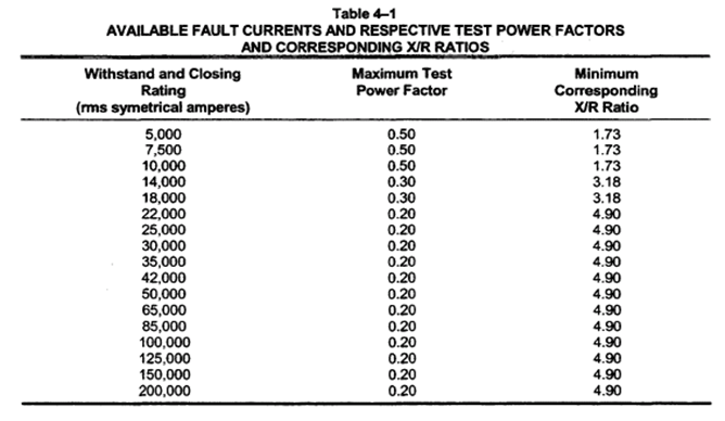
Withstand and Closing Ratings – Transfer switch equipment shall have withstand and closing ratings, expressed in maximum available fault current (rms symmetrical amperes) at maximum rated voltage, and marked in accordance with UL 1008 and this standard. The type and rating of any associated protective devices necessary to meet the requirements of UL 1008 shall also be marked on the transfer switch equipment.The withstand and closing current rating shall be one of the values specified in Column 1 of Table 4-1 (Attachment 2). Standard withstand and closing ratings are based on transfer switch equipment testing conducted at maximum allowable test circuit power factors and corresponding minimum X/R ratios specified in Table 4-1. When applying transfer switch equipment, consideration should be given to both available fault current and circuit X/R ratio at the point of application. (NEMA ICS10, P-1, Sec 4.1.6)
“The nameplate markings for transfer switches shall include:
a. Name of manufacturer and catalog number, or the equivalent serial number
b. Voltage and frequency ratings
c. Continuous current rating
Additional markings shall be those required by UL 1008 and shall include the following, where applicable:
d. Suitability for emergency or standby service as defined by the NEC
e. Suitability for specific loads. See 4.3.5 of UL 1008
f. Suitability for use as service equipment
g. Interrupting or short-circuit ratings
For Type A: Short-circuit rating or conditional short-circuit rating with the type and rating of the additionally required short-circuit protective device
For Type B: Interrupting rating
h. Cautions or warnings, or both
i. Automatic or nonautomatic (NEMA ICS10, P-1, Sec 5.1.1)”
“The nameplate markings for bypass/isolation switches shall include:
a. Name of manufacturer and catalog number, or the equivalent serial number
b. Voltage and frequency ratings
c. Continuous current rating
(NEMA ICS10, P-1, Sec 5.1.2)”
Spacing in automatic transfer switches and bypass isolation switches shall be not less than those shown in Table 7-1 (Attachment 1). (NEMA ICS10, P-1, Sec 7.1)
The arrangement of the wiring space shall be such that the normal and alternate supply conductors can be kept separated. (UL 1008, Sec.23.2)
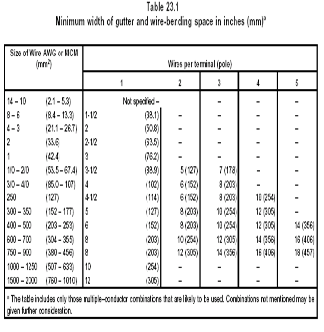
The wire-bending space from a connector to any barrier or other obstruction that is part of a transfer switch shall be as specified in Table 23.1(Attachment 3).(NEMA ICS10, Sec.23.4)
“Automatic transfer switching equipment shall be classified as Class PC or Class CB.
Class PC: ATSE that is capable of making and withstanding, but is not intended for breaking short-circuit currents.
Class CB: ATSE provided with overcurrent releases and the main contacts of which are capable of making and are intended for breaking short-circuit currents. (IEC 60947-6-1, Sec 3)”
All internal devices and components shall be provided with an identifying number or a nameplate to identify the item and its function. Nameplate abbreviations shall match the item description shown on the UPS schematic drawings.
“Instruction Manuals
Each system shall be provided with instruction manual(s) including the following information as a minimum. The required number of sets shall be as specified on the buyer’s Non-Material Requirements for Interruptible Power Supply (UPS) Form NMR-9597.
a) Installation & commissioning instructions
b) Operating instructions
c) Wiring & schematic diagrams
d) Service instructions with calibration & trouble shooting guide
e) Factory Test procedures & Certified test reports”
International Standard and Codes for UPS Static Switch
- Non-Hazardous Indoor Enclosures, Installation and Pre-Commissioning
- Boxes, Enclosures, and Accessories Materials Selection & Requirements
- UL 1008 Transfer Switch Equipment, November 1996
- IEC-60947-6 LV Switchgear & Controlgear – Transfer Switching Equipment, August 2005
- NEMA ICS 10 Industrial Control & Systems – Electromechanical AC Transfer Switch Equipment, January 2005
- 16-SAMSS-521 Indoor Automatic Transfer Switch – Low Voltage, 21 May 2007
- SAES-P-101 Regulated Vendor’s List for Electrical Equipment, 09 June 2007
- SAES-P-100 Basic Power System Design Criteria, 25 June 2007
- SAES-P-116 Switchgear and control Equipment, 01 March 2008
- 17-SAMSS-516 Uninterruptible Power Supply System.
1. Attachment – 1 NEMA ICS10 Table 7.1 Spacings
2. Attachment – 2 UL 1008 Table 23.1 Minimum Width of Gutter and wire bending space


