This article provides general maintenance and calibration information on fixed non-contact Machinery Vibration Monitoring Equipment. Main keywords for this article are Vibration System Basic. Vibration System Troubleshooting. Axial Calibration Arrangement. Radial Calibration Arrangement. Vibration System Maintenance.
Vibration System Basic
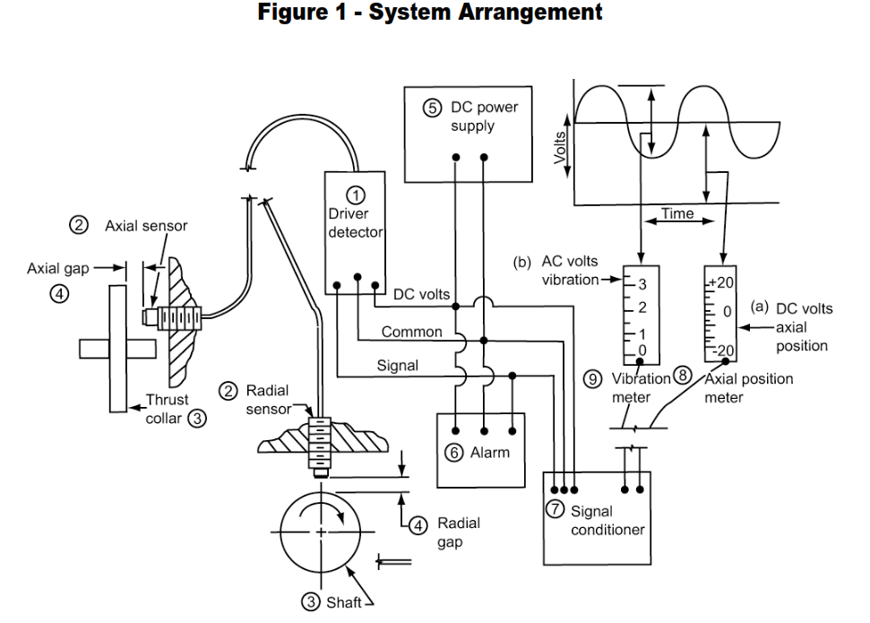
- A noncontact vibration monitor is an instrument for measuring either axial position in mils or radial vibration, by means of an eddy-current sensor, refer to Figure 1. Highfrequency electrical energy is provided by a driver detector (1) connected to a sensor (2), which produces a magnetic field. The signal strength varies with the magnetic energy absorbed by the shaft or thrust collar (3) as a result of variations in gap (4). The sensor and monitor are powered by a regulated power supply (5). The signal enters an alarm trip circuit (6) and a conditioning circuit (7). The signal conditioner provides a DC carrier voltage (a) proportional to the average gap, and an ac voltage (b) proportional to the change in gap due to shaft motion. The DC voltage of the average axial gap is displayed in mils on meter (8) or the AC voltage is displayed as mils peak-to-peak radial vibration amplitude on meter (9). Outputs from the system may feed recorders, oscilloscopes, alarms or shutdown interlocks. These basic principles apply to most systems.
- These instruments can be modified by circuit changes to indicate velocity.
Test and Installation Equipment
- All the listed equipment must be provided with suitable interface hardware.
- Standard material for barrel tip Figure 2 item 13 and wobble plate Figure 4 item 3 are AISI C 4140. This is compatible with C 4140 carbon steel, 400 series and 17-4 PH stainless steels. For other shaft materials or for coated units, the barrel tip and wobble plate shall be the same as the shaft.
Basic test equipment
a. A gap micrometer (see Figure 2)
b. A mechanical wobble plate sine wave generator (see Figure 4)*
c. A volt ohmmeter with 20,000 ohms/volt minimum sensitivity
An oscilloscope to determine surface characteristics, verify readings, and analyze wave forms
Optional test equipment
A DC data tape recorder
A tuneable filter analyzer
A portable vibration monitor
A digital tachometer
Real time spectral analyzer
The Indikon system has an internal electronic calibrator but will check only one point on the scale. Use of a commercially available wobble plate is still recommended.
Installation Procedures
- Sensors
- Axial position sensors are mounted within 12 inches of thrust bearing to minimize effect of thermal growth of the shaft. Observed surface should be perpendicular to shaft axis and preferably, the thrust collar should be used.
- Radial vibration sensors are mounted radially to shaft, preferably through or close to a journal bearing.
- General
a. Sensors shall be rigidly mounted.
b. Sensors must have positive locking device.
c. Holes for sensor should be a medium running fit.
d. Sensors with nonshielded tips must be provided with specific peripheral clearance. (Shielded tips require no clearance to surrounding metal surfaces.)
e. Leads should be provided with mechanical protection either in the form of conduit or attached armor.
- Driver detectors must be mounted in weatherproof boxes within the calibrated lead length of the sensor.
- Sensor leads and cables
- The lead between the sensor and the detector should be Teflon® fluorocarbon resin coated shielded coaxial cable with suitable connectors. It must be of the length specified for system calibration.
- The cable between the detector and monitor should be three-wire shielded, installed as any low voltage signal line, and compatible with electrical classification of area in which it is to be used.
- Surface observed by sensors should be ground to same finish and concentric within 0.0002 inch with bearing journal areas. Chrome-plated and some other coated surfaces will result in inaccurate readings.
Calibration and Alarm Settings
-
Volts vs. Gap Curve
It is recommended that the volt vs. gap curve be measured and a permanent record kept for both axial position and radial vibration monitors as a check of vendor quality and proper system installation. The actual sensor, lead cable, and driver detector are used.
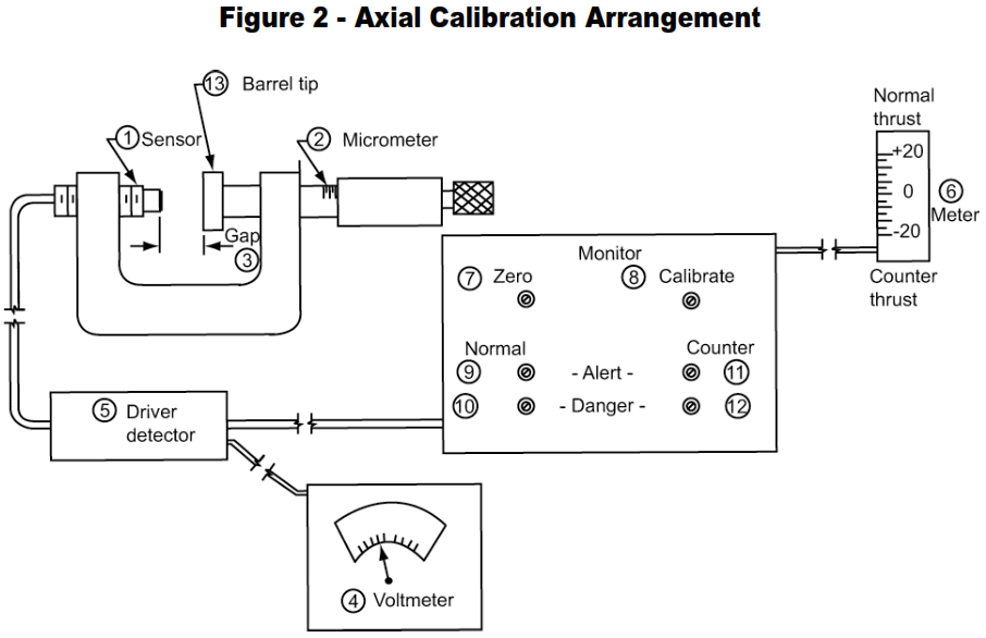
- The equipment shown on Figure 2 is used to generate the volt vs. gap data as follows:
This is combined with the signal conditioner in the Indikon system and an intermediate signal amplifiers substituted- a. Lock the sensor (1) in the micrometer unit (2) so that the sensor lightly contacts the micrometer barrel tip (13) when the micrometer is set to zero.
- b. Increase the gap (3) at 0.005-inch increments by moving the barrel tip of the micrometer away from the sensor.
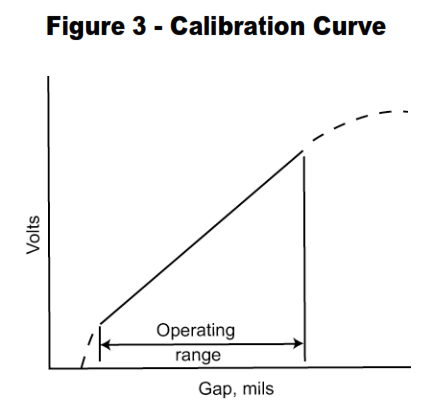
- c. Record the output voltages (4) from the driver detector (5) for the set gap in mils repeating b and c at least 10 times. Plotting the volt vs. gap as shown on Figure 3. This curve should be linear within the operating range of the sensor.
- Installed gap is set by measuring the potential between the common andsignal leads, and adjusting the sensor until proper voltage is obtained for themodel used.
- The equipment shown on Figure 2 is used to generate the volt vs. gap data as follows:
-
Axial position monitors / Axial Calibration Arrangement
Axial position monitors are calibrated as shown on Figure 2 and following the outlines procedure. An electrically similar probe and lead cable can be substituted for equipment already installed:
- Lock the sensor (1) in the micrometer unit (2) and adjust per above paragraph.
- Move the micrometer barrel tip (13) away from the sensor until the gap voltage (4) reads the same as the initial zero gap (3) set on the machine.
- The monitor meter (6) should indicate zero. If not, turn the “zero” adjusting potentiometer (7) until the meter reads exactly zero.
- Record the zero gap and voltage.
- At this point the test circuit of the monitor should be satisfied and the appropriate signal light is activated.
- Move the micrometer barrel tip (13) 0.010-inch closer to the sensor; the meter should read 10-mil normal thrust. Turn the micrometer back to the initial zero gap (Step d) then move the micrometer barrel tip (13) 0.010 inch away from the sensor; the meter should read 10-mil counterthrust. If not, turn the “calibrate” potentiometer (8) until the correct span is obtained.
- An additional check may be made with the installed unit by thrusting the machine rotor full normal and counterthrust, and comparing the change in position shown on the meter against the measured motion.
-
Radial Vibration Monitors / Radial Calibration Arrangement
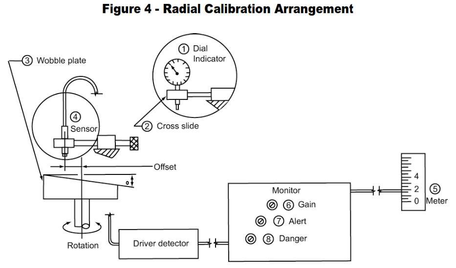
Radial Vibration Monitors are calibrated with a mechanical sine wave generator as shown in Figure 4 and following the outlined procedure. As with axial monitors, an electrically similar sensor and lead cable may be substituted:
- Clamp the dial indicator (1) in the cross slide (2) and slowly rotate the wobble plate (3) by hand. Adjust the cross slide to obtain a 0.003-inch total indicator reading.
- Remove the dial indicator and clamp the sensor (4) in the cross slide. Do not move the cross slide adjustment. Gap the sensor electrically per 6.1.2 or with a plastic feeler gage. Caution: Do not scratch wobble plate surface.
- This should satisfy the test circuit and the appropriate signal light is activated.
- Before turning on wobble plate drive, zero the meter mechanically.
- Turn on the wobble plate drive motor. The sine wave signal generated due to the angle (a) should be indicated as 3.0-mil peak-to-peak vibration on monitor meter (5). If not, turn the “gain” potentiometer (6) until the correct reading is obtained.
- Recorders, if used, are calibrated by inducing inputs per 2 or 3 above mentioned.
Vibration recorders usually have a gain adjustment only. Position recorders have both zero and gain adjustment. The adjustment potentiometer may be on the recorder, monitor, or an interconnecting component. - Alarm settings on most monitors include both alert and danger trip relay circuits.
These may or may not be connected for shutdown inter-lock. Relay trip levels are set by actuating the proper alarm set button and adjusting the corresponding potentiometer to obtain the desired trip level. These alarm settings should be checked by inducing inputs per 2 or 3 and recording trip points:.
a. Axial position monitors have both positive and negative alert and danger levels (4 circuits, as shown on Figure 2, Items 9 through 12)
b. Radial vibration monitors have single alert and danger levels (2 circuits, as shown on Figure 4, Items 7 and 8)
Vibration System Troubleshooting
- It may be necessary at times to diagnose system problems when an alarm or upset occurs. However, when these systems have been installed properly and calibrated, they have demonstrated a high reliability.
- Do not assume the monitors are at fault when an alarm is given.
- Check the alarm condition by observing waveform on an oscilloscope, bearing temperature, oil pressure, oil temperature, thrust load, or other critical process variables. If none of these verify the alarm, check power supply, fuses, switches, bulbs, meters, and circuits.
- Axial position monitor checks
- Supply and signal voltage
- Driver detector calibration per 6.1.1 using test sensor and cable, or replace with pretested spare.
- Resistance of sensor and cable
- Signal conditioner circuit or replace with pretested spare
- Meter or replace with pretested spare
- Radial vibration monitor checks
- Waveform on oscilloscope
- Supply and signal voltage
- Drive unit with electrically similar sensor and cable as per 6.3 to test monitor and driver circuits
- Resistance of sensor and cable
- Driver detector calibration per 6.1 or replace
- Signal conditioner circuit or replace
- Meter or replace with pretested unit
- Alarm relay check
- Trip circuit or
- Replace with pretested unit
Vibration System Maintenance and Spare Parts
Recommended maintenance and spare parts are a function of required availability of the unit protected and should be analyzed individually.


