Upon completion of this article, the learners will be able to:
- Briefly explain the operation of High Speed Downlink/Uplink Packet Access (HSDPA/HSUPA) in the WCDMA RAN P5 Network.
- Explain the operation of the Ericsson simulation tool used for HSDPA/HSUPA dimensioning.
- Explain how the HSDPA/HSUPA capacity and coverage data rates are calculated.
This article provides an overview of High Speed Downlink Packet Access (HSDPA) and High Speed Uplink Packet Access (HSUPA) channels. It explains how to use the Ericsson HSxPA simulation tool to estimate the capacity and coverage rates of these channels, based on the remaining capacity from R99 dimensioning. The tool also helps determine the number of sites needed to meet specific HSxPA network requirements.
High Speed Downlink Packet Access.
The High Speed Downlink Packet Access (HSDPA) service surpasses the R99 PS RAB limit of 384 Kbps by using three basic principles, as shown in Figure below.
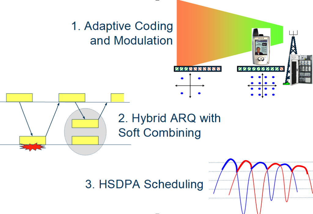
In theory, HSDPA can achieve downlink data rates over 14 Mbps, but the actual user rate depends on the capability of the UE (User Equipment).
Adaptive Coding and Modulation.
When a UE is served by a WCDMA R99 RAB, the power for the Quadrature Phase Shift Keying (QPSK) channel is adjusted based on the radio environment. Poor environments need more power than good ones to maintain the same Block Error Rate (BLER) or Bit Error Rate (BER). A fixed amount of Forward Error Correction (FEC), such as Turbo or Convolutional coding, is also applied to correct errors. To achieve higher rates with HSDPA, the first step is to adapt the amount of coding applied to the channel according to the radio environment.
Adaptive Coding.
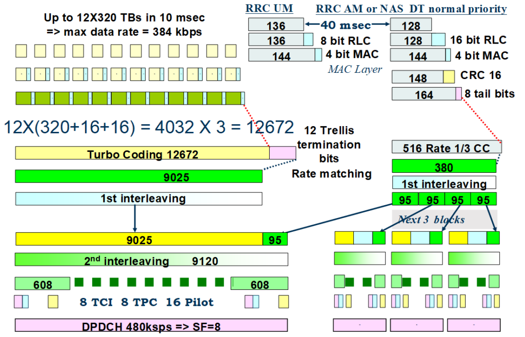
The R99 Packet Switched (PS) 384 downlink Radio Bearer (RB) mapping is illustrated in Figure below. The maximum user data Transport Format (TF) consists of twelve 320-bit blocks in 10 milliseconds, achieving a user data rate of 384 kbps. Each 320-bit block includes a 16-bit RLC header and a 16-bit CRC, making a total of 352 bits per block.
Twelve of these blocks result in:
12×(320+16+16)=4224 bits
These 4224 bits are fed to a Rate 1/3 Turbo coder, which produces 2 parity bits for every input bit, resulting in:
3×4224=12672 bits
Additionally, there are 12 ‘Trellis Termination bits,’ making the total:
12672+12=12684 bits
The output of the Turbo Coder is rate matched down to 9025 bits. When 95 control plane bits are added, the combined 9120 bits are carried by an SF 8 Orthogonal Code.
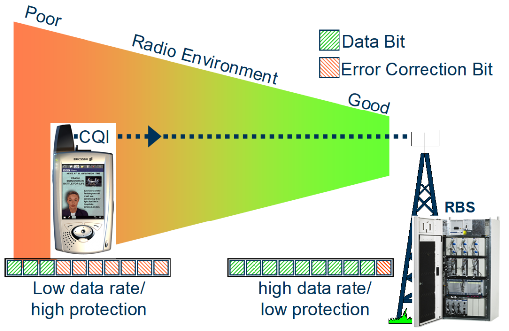
To achieve higher user data rates in HSDPA, the number of parity bits from the Turbo Coder is adjusted based on the radio environment. In poor radio environments, the maximum number of parity bits is used to provide strong error protection. Conversely, in good radio environments, some parity bits can be punctured (removed), which allows for higher user data rates but with lower error protection, all while using the same physical channel.
As shown in Figure below:
- Poor Radio Environment: More error correction bits are used, which reduces the user data rate but improves error protection.
- Good Radio Environment: Fewer error correction bits are used, which increases the user data rate but provides less error protection.
This adaptive approach allows HSDPA to optimize data rates and reliability according to the varying conditions of the radio environment.
In HSDPA, a 2 millisecond Transmission Time Interval (TTI) is used, which allows the coding scheme to be adapted every 2 milliseconds, or 500 times a second. This rapid adaptation is crucial to adjust to the fast-changing radio environment.
Each User Equipment (UE) utilizing the HSDPA channel must continuously report its Channel Quality Indicator (CQI) to the Radio Base Station (RBS). This reporting enables the RBS to dynamically adjust the coding scheme according to the current radio conditions.
Adaptive Modulation.
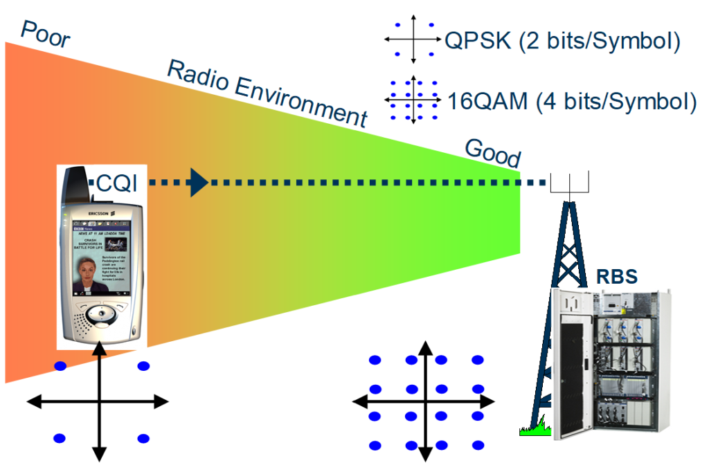
Quadrature Phase Shift Keying (QPSK) modulation, which transfers two bits of information per modulation symbol, is used for all R99 RABs. In contrast, 16 Quadrature Amplitude Modulation (16QAM) is used in HSDPA to increase the data rate, where each modulation symbol transfers four bits of information.
However, 16QAM is less robust and typically requires higher energy per bit for a given error rate compared to QPSK. Therefore, the decision to use 16QAM depends on the radio environment. In poor radio environments, where robustness is critical, QPSK is preferred. In good radio environments, where higher data rates are desired and the channel conditions allow, 16QAM is used.
The RBS adapts the modulation scheme from QPSK in poor radio environments to 16QAM in good environments, as illustrated in Figure below. This adaptive modulation scheme ensures that the HSDPA system optimizes data rates while maintaining reliable communication under varying radio conditions.
It should also be noted that 16QAM can only be used when there is sufficient power available at the Radio Base Station (RBS).
Again, the 2 millisecond Transmission Time Interval (TTI) of HSDPA allows the modulation scheme to be adapted every 2 milliseconds, or 500 times a second, in line with the rapid changes in the radio environment.
Each User Equipment (UE) using the HSDPA channel must continually report its Channel Quality Indicator (CQI) to the RBS to facilitate the adaptation of the modulation scheme.
HSDPA uses SF 16 (Spreading Factor 16) Orthogonal codes, which allow for a theoretical maximum of 15 to be allocated to a single user or shared in the time and/or code domain, leaving enough codes for common channels.
In the Ericsson P4 WCDMA RAN, a maximum of 5 Orthogonal Codes can be allocated to HSDPA, with sharing in the time domain only. A physical channel rate of 2.4 Mbps can be achieved using all 5 OCs with QPSK modulation, and 4.8 Mbps with 16QAM, as illustrated in figure below.
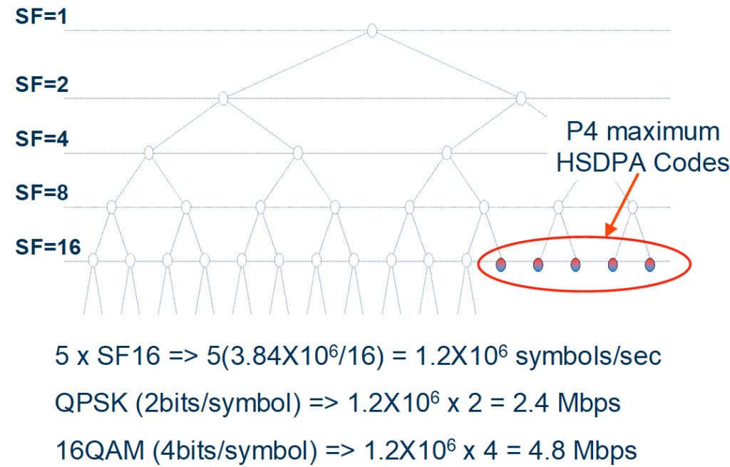
In the P5 WCDMA RAN, a physical data rate of up to 14.4 Mbps can be achieved using 15 Orthogonal Codes (OCs). However, the rate measured at the Radio Link Control (RLC) layer will be lower than this due to factors such as Forward Error Correction (FEC), CRC checksum, MAC headers, and Layer 3 signaling. The effective rates will range from 0.16 Mbps with one OC and QPSK modulation to 13.9 Mbps with 15 OCs and 16QAM modulation.
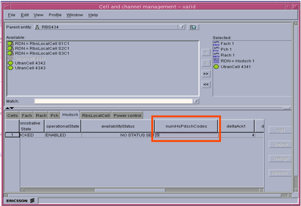
The number of OCs used is configured using the ‘numHsPdschCodes’ Cell parameter, as illustrated in the OSS-RC (Operation Support System – Radio Configuration) ‘Cell and Channel Management’ GUI shown in Figure below.
Hybrid ARQ with Soft Combining.
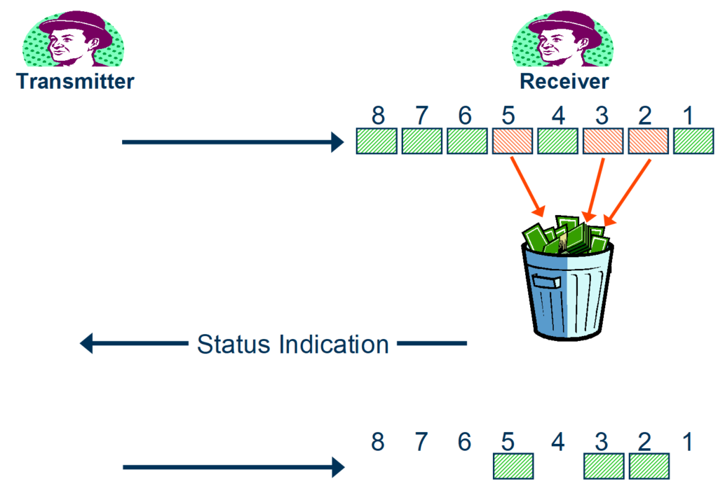
In a conventional Automatic Retransmission Request (ARQ) scheme, such as that employed by the AM RLC (Acknowledged Mode Radio Link Control), a series of Protocol Data Units (PDUs) are transmitted. After transmitting these PDUs, a ‘polling indication’ bit is sent. The receiver discards any PDUs that have errors and responds to the ‘polling indication’ with a ‘status indication’, informing the transmitter about which PDUs were correctly received.
Upon receiving the status indication, the transmitter will re-send the PDUs that were not received correctly (errored PDUs). This ‘polling’ ARQ system is illustrated in Figure below.
For HSDPA, a ‘Stop And Wait’ (SAW) ARQ algorithm is used, where the transmitter waits for an Acknowledgement (ACK) before sending the next Protocol Data Unit (PDU) or retransmitting if a Negative Acknowledgment (NAK) is received. Unlike traditional ARQ, where errored PDUs are discarded, the HSDPA User Equipment (UE) stores the errored PDU and combines it with the retransmitted one to improve error correction. This process is known as ‘soft combining’.
Since the Round Trip Time (RTT) for the HSDPA channel is typically 12 milliseconds, it could take over six 2 millisecond frames for the UE to receive the retransmission. To enable data to be sent to the same UE in consecutive HSDPA frames, multiple ARQ processes are used to transfer data to the UE. This principle of combining multiple ARQ processes is called ‘Hybrid ARQ’ (HARQ).
The concept of Hybrid ARQ with soft combining is illustrated in figure below.

When the first transmission of the PDU from ARQ process number 1 (P1, 1) is received incorrectly, a NACK is sent, and the data is buffered. Given the RTT of approximately 12 milliseconds, it takes 6 frames for the retransmission (P1, 2) to arrive at the UE. During this time, ARQ processes 2-6 have already sent their data. Soft combining is then performed on the original transmission (P1, 1) and the retransmission (P1, 2), and an ACK is sent.
The data retransmitted depends on whether ‘Chase Combining’ or ‘Incremental Redundancy’ (IR) algorithms are used:
- Chase Combining: Each retransmission is an identical copy of the original transmission.
- Incremental Redundancy (IR): The retransmission includes the error correction bits that were initially punctured out.
The Ericsson P4 WCDMA RAN uses only Chase Combining.
To support soft combining, the UE must have sufficient buffer capacity to store at least 6 ARQ processes. An extra rate matching stage is used for HSDPA to ensure that the transmission does not exceed the UE buffer size. This involves puncturing the Turbo Coding parity bits to match the UE buffer size. This first stage rate matching is followed by a second stage rate matching, which matches the data rate to the physical channel rate in the same manner as R99 channels.
Figure below illustrates how a 2404-bit HSDPA Transport Block (TB) could be mapped onto four SF 16 Orthogonal Codes.
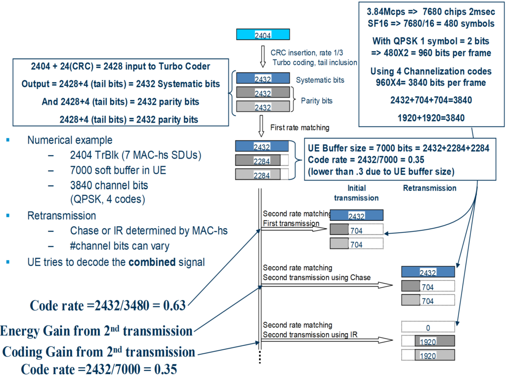
The difference between what is retransmitted with Chase Combining and Incremental Redundancy (IR) is clearly illustrated in Figure above.
- Chase Combining: The retransmitted data is an identical copy of the initial transmission. This provides an energy gain when the retransmission is combined with the initial transmission.
- Incremental Redundancy (IR): The retransmitted data includes the error correction bits that were initially punctured out, providing a coding gain. This means that the coding rate is effectively reduced from 0.63 to 0.35 with the retransmission, improving error correction capabilities.
HSDPA Scheduling.
The Ericsson RBS (NodeB) uses one of two different algorithms to control the scheduling of HSDPA among users. This scheduling algorithm aims to make the most efficient use of the HSDPA channel while ensuring acceptable data rates for each user. It is sometimes referred to as ‘channel-dependent scheduling’ because it relies on the instantaneous channel conditions.
The basic idea behind channel-dependent scheduling is to transmit at the peaks of the fading channel to increase capacity and use resources more efficiently. However, this approach can result in large variations in user data rates, requiring a trade-off between capacity and user data rates.
The two NodeB algorithms supported by the Ericsson RBS for channel-dependent scheduling are illustrated in Figure below.

When the RBS is using the Proportional Fair algorithm, it schedules the user with the highest ‘Queue Selection Coefficient’ in every Transmission Time Interval (TTI). The NodeB scheduling algorithm is managed by the ‘Queue Select Algorithm’ RBS parameter. This is shown in the RBS Element Manager screenshot in Figure below.

For dimensioning purposes, it is assumed that the ‘PROPORTIONAL_FAIR’ algorithm is used.
HSDPA Transport and Physical Channels.
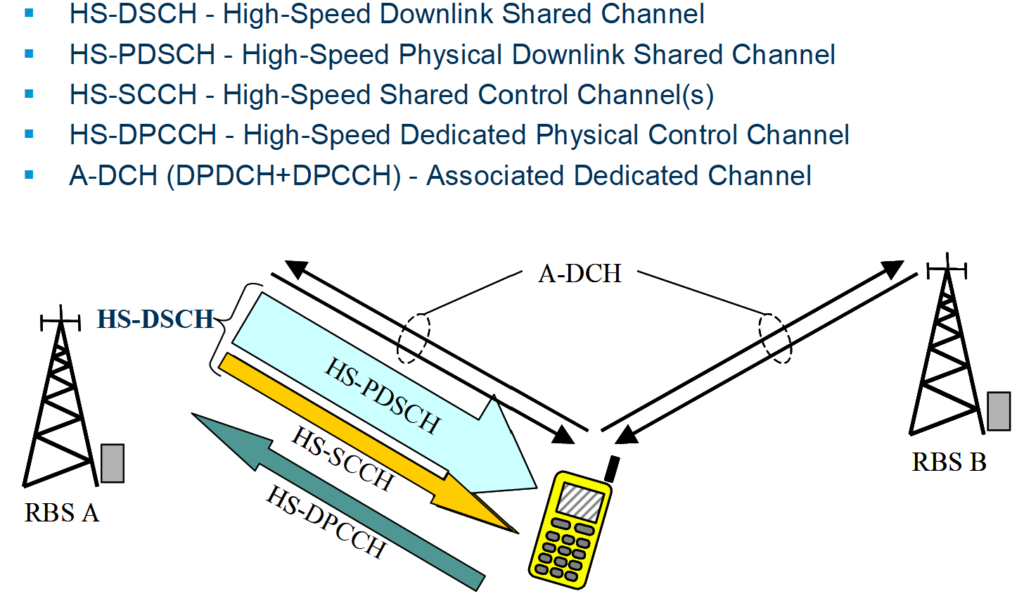
Three new physical channels and one transport channel are required to implement HSDPA in the WCDMA RAN, as illustrated in Figure below.
To implement HSDPA in the WCDMA RAN, the following channels are required:
- HS-DSCH (High-Speed Downlink Shared Channel): This downlink transport channel carries user data from the RNC to the RBS.
- HS-PDSCH (High-Speed Physical Downlink Shared Channel): This downlink physical channel carries the user data and layer 2 overhead bits over the air interface, using up to 15 Orthogonal Codes (OCs).
- HS-SCCH (High-Speed Shared Control Channel(s)): This downlink physical channel carries control information about the type of modulation and OCs used in the HS-PDSCH. This channel is broadcast to all UEs, but only the scheduled one will receive the necessary information to decode the HS-PDSCH.
- HS-DPCCH (High-Speed Dedicated Physical Control Channel): This physical uplink channel is used by the UE to send ACK/NAK for received Transport Blocks and channel quality reports required by the scheduling algorithm.
Each connection also has an associated dedicated transport channel (A-DCH) allocated in the cell. The A-DCH is mapped onto physical channels DPDCH and DPCCH.
HSDPA Terminal Categories.
The 3GPP have defined 12 HSDPA categories illustrated in Figure below.
| HSDPA category | Max HSDPA Codes | L1 peak rates (Mbps) | QPSK/16QAM | Max 10 msec Transport Block size | RLC Max bit rate (Mbps) |
| Category 1 | 5 | 1.2 | Both | 7298 | 3.6 |
| Category 2 | 5 | 1.2 | Both | 7298 | 3.6 |
| Category 3 | 5 | 1.8 | Both | 7298 | 3.6 |
| Category 4 | 5 | 1.8 | Both | 7298 | 3.6 |
| Category 5 | 5 | 3.6 | Both | 7298 | 3.6 |
| Category 6 | 5 | 3.6 | Both | 7298 | 3.6 |
| Category 7 | 10 | 7.3 | Both | 14411 | 7.2 |
| Category 8 | 10 | 7.3 | Both | 14411 | 7.2 |
| Category 9 | 15 | 10.2 | Both | 20251 | 10.1 |
| Category 10 | 15 | 14.0 | Both | 27952 | 13.98 |
| Category 11 | 5 | 0.9 | QPSK | 3630 | 1.8 |
| Category 12 | 5 | 1.8 | QPSK | 3630 | 1.8 |
All HSDPA UE categories are supported in the Ericsson P5 WCDMA RAN.
High Speed Uplink Packet Access.
The High Speed Uplink Packet Access (HSUPA) service can achieve data rates higher than the R99 PS RAB limit of 384 Kbps by using three main principles, as shown in Figure below.

It uses the same Hybrid ARQ with soft combining process as HSDPA. Additionally, the uplink outer loop algorithm is adjusted for HSUPA.
Multi-Code Operation.
To increase the uplink rate for HSUPA, the UE can use up to 4 simultaneous Orthogonal Codes (OCs) with Spreading Factors (SF) of 2 or 4. Hybrid Phase Shift Keying (HPSK) is used in the uplink, allowing the same OCs to be used for HSUPA because they are placed on different branches of the modulator.
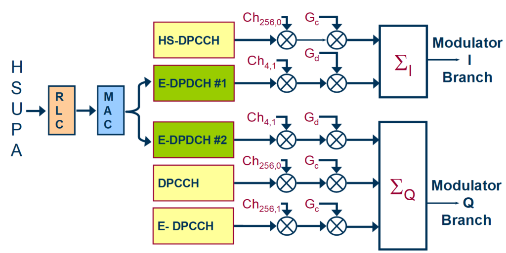
HSUPA operating with two SF 4 OCs is illustrated in Figure 9.16 below. The physical rate of one SF 4 OC is (3.84/4) = 0.96 Mbps, and for SF 2 it is (3.84/2) = 1.92 Mbps. Thus, the HSUPA physical rates range from 0.96 Mbps to 3.84 Mbps.
The rate measured at Radio Link Control (RLC) will be lower than this due to Forward Error Correction (FEC), CRC checksum, MAC headers, and Layer 3 signaling, ranging from 0.73 Mbps to 5.7 Mbps.
HSUPA Scheduling.
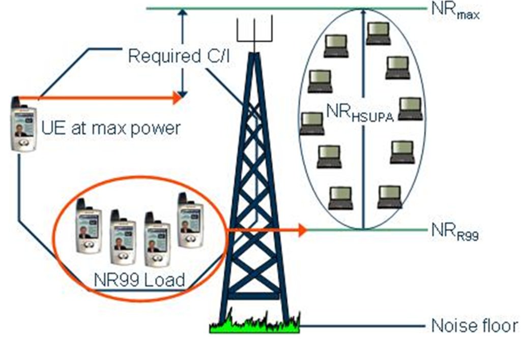
The function of the HSUPA scheduler is to allocate the remaining uplink interference headroom after all R99 services have been allocated. The maximum allowed noise rise (NRmax) in a cell is calculated based on the uplink budget, ensuring that a UE transmitting at maximum power can still achieve its required Carrier-to-Interference ratio (C/I) if the noise level is kept below this value.
The R99 Noise Rise (NRR99) is determined from the uplink R99 load. The available noise rise for HSUPA (NRHSUPA) is then calculated as the difference between NRmax and NRR99.
NRmax, NRR99, and NRHSUPA are illustrated in Figure below.
Sure, here’s a simplified rewrite:
It’s important to note that HSUPA users can increase interference not only in their serving cell but also in neighboring cells. Because of this, non-serving cells are allowed to control the HSUPA rate as well.
Every 10 milliseconds, the HSUPA scheduler determines the maximum rate it will grant to each HSUPA connection based on measurements of uplink interference, Iub capacity, and RBS hardware (channel elements). This rate is sent to the UEs in a coded form via a grant message. The UE uses this message to select an appropriate rate and determine the relative amount of power for transmission. The absolute power used is the sum of the relative power and the power given by the inner loop power control. The UE receives this ‘Absolute Grant’ message from the serving cell.
Additionally, HSUPA users increase interference in non-serving cells, so their power can be adjusted by ‘Relative Grant’ messages from all non-serving cells.
The UE also measures link quality itself and can judge whether the current rate is adequate using link quality mapping data provided by the network at call setup. It informs the network whether it is satisfied or not with a so-called “happy bit”. This information is fed into the scheduler.
If supported by the terminal, the Transmission Time Interval (TTI) can be reduced to 2 milliseconds. This shorter TTI allows the scheduler to better track uplink interference and thereby increase the throughput of the HSUPA channel.
Modified Outer Loop Power Control.
The outer power control loop in HSUPA adjusts the Signal-to-Interference Ratio (SIR) target for the inner loop, similar to R99 channels. However, because of the Hybrid Automatic Repeat Request (HARQ) protocol used in HSUPA, the Block Error Rate (BLER) is typically close to zero. Therefore, BLER, which is the control variable for the outer power loop in R99 channels, is not suitable for HSUPA. Instead, the number of HARQ retransmissions is used as the control variable. The RBS reports this number to the outer loop power control function in the RNC.
HSUPA Transport and Physical Channels.
To implement HSUPA in the WCDMA RAN, five new physical channels and one transport channel are required. These channels are illustrated in Figure below.
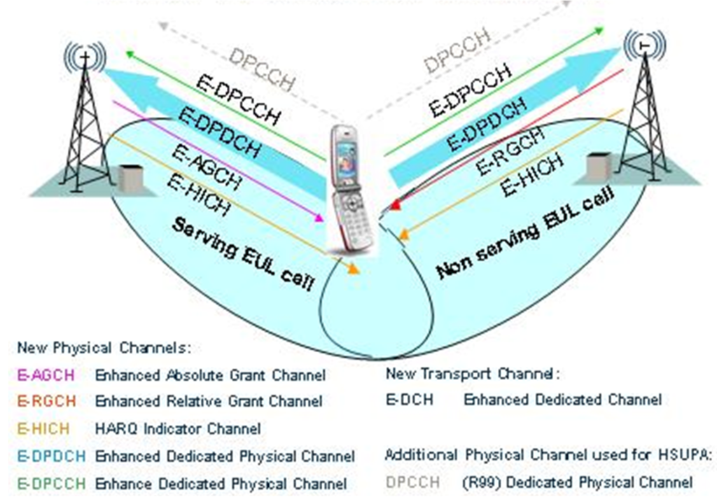
In Figure above, the UE is shown in soft handover, which means it is connected to at least one non-serving cell in its Active Set (AS).
The transport channel used to carry HSUPA data on the Iub interface is called the Enhanced Dedicated Channel (E-DCH). This channel is mapped to several E-DPDCH and one E-DPCCH physical channels. It corresponds to a set of uplink Channelization codes, each using QPSK modulation, with the spreading factor dependent on the instantaneous data rate.
The uplink E-DPDCH and E-DPCCH physical channels are jointly inner loop power controlled with the DPDCH and HS-DPCCH channels, using the DPCCH.
In soft handover, the handling of power orders works in the same way as for R99 channels and is controlled jointly with them. The Transmit Power Control (TPC) commands used to control the power of all uplink channels are carried by the R99 DPCH in the downlink.
HSUPA Downlink Physical Channels.
Here’s a explanation of the three downlink physical channels associated with HSUPA:
- E-AGCH: Enhanced Absolute Grant Channel
- Function: The E-AGCH is a shared downlink channel used to transmit absolute grants. These grants are sent by the scheduler to UE (User Equipment), providing information on the rate and transmission power it should use. Multiple users share one E-AGCH channel.
- Operation: Each UE listens to the E-AGCH in its serving cell. The UE targeted for a specific grant is identified using direct addressing (E-RNTI).
- Configurability: Operators can configure multiple E-AGCH channels based on the number of users allowed to transmit simultaneously on the E-DCH (Enhanced Dedicated Channel) in a cell.
- Power Configuration: The power of E-AGCH is set as the maximum total power allowed for all configured E-AGCH channels per cell, depending on the number of simultaneous EUL (Enhanced Uplink) users allowed to transmit.
- Technical Details: E-AGCH uses a spreading factor (SF) of 256.
- E-RGCH: Enhanced Relative Grant Channel
- Function: E-RGCH is a downlink channel that carries relative grants. These grants are sent by non-serving cells to UE, indicating whether the UE should decrease its transmission rate or not.
- Operation: Each UE listens to E-RGCH in all its non-serving cells. The channel uses different orthogonal sequences (signature sequences) to address individual HSUPA connections.
- Broadcast Nature: E-RGCH operates as a broadcast channel, allowing quick reactions to network overload by transmitting commands like “DOWN” to entire groups of UEs.
- Configurability: Operators can configure multiple E-RGCH channels based on the number of users allowed to transmit simultaneously on E-DCH.
- Power Configuration: E-RGCH is configured with fixed power similar to E-HICH (HARQ Indicator Channel).
- Technical Details: E-RGCH uses a spreading factor (SF) of 128.
- E-HICH: HARQ Indicator Channel
- Function: E-HICH is a dedicated downlink channel that carries binary Hybrid Automatic Repeat Request (HARQ) acknowledgements. It indicates whether a transport block has been correctly received.
- Operation: Each HSUPA user in the active set of cells has an E-HICH dedicated to it. The channel uses individual signature sequences for each user.
- Transmission Characteristics: Serving and non-serving cells transmit ACKs and NAKs differently, allowing NAKs to be transmitted with lower power.
- Configurability: E-HICH is configured jointly with E-RGCH, with each user getting an individual signature sequence.
- Technical Details: E-HICH uses a spreading factor (SF) of 128.
These channels work together to manage the uplink transmission efficiently in HSUPA, ensuring that users receive the necessary instructions and feedback from the network.
HSUPA Uplink Physical Channels.
Here’s a explanation of the three uplink physical channels associated with HSUPA:
- E-DPDCH: Enhanced Dedicated Physical Data Channel
- Function: The E-DPDCH is the data transport channel used for uplink transmission in HSUPA. Each Enhanced Uplink (EUL) user has one or two E-DPDCHs allocated across all cells in its active set.
- Power Control: The power of E-DPDCH is dynamically set as an offset to the DPCCH using a gain or beta factor. This beta factor is signaled in the grant messages from the scheduler.
- Technical Details: E-DPDCH uses a spreading factor (SF) of 256 and can operate in soft handover.
- E-DPCCH: Enhanced Dedicated Physical Control Channel
- Function: The E-DPCCH is used to transmit channel condition information from the UE to the scheduler. It includes the Retransmission Sequence Number (RSN), information about the used data rate, and the “happy” bit which indicates UE satisfaction with its allocated rate.
- Power Control: E-DPCCH power is set relative to the DPCCH using a fixed beta factor. It uses SF=256 and is power controlled by the inner loop.
- Transmission Frequency: Information on the E-DPCCH is repeated five times within a 10 ms Transmission Time Interval (TTI).
- DPCCH: R99 Dedicated Physical Control Channel
- Function: The DPCCH is the R99 Layer 1 signaling channel that carries power control information (TPC bits) and pilot bits.
- Power Control: The DPCCH is used for power control of all uplink channels, including the E-DPCCH.
- Role in HSUPA: While primarily an R99 channel, DPCCH plays a crucial role in HSUPA for transmitting power control commands and maintaining synchronization.
These channels work together to manage and optimize the uplink transmission in HSUPA, ensuring efficient use of resources and effective communication between the UE and the network scheduler.
HSUPA Terminal Categories.
The 3GPP have defined 6 HSUPA categories illustrated Figure below.
| HSUPA category | Max No. Multi-codes | Min SF | TTI Support 10 / 2 msec | Max 10 msec Transport Block size | Max 2 msec Transport Block Size | RLC Max bit rate (Mbps) |
| Category 1 | 1 | 4 | 10 ms ONLY | 7110 | – | 0.7 |
| Category 2 | 2 | 4 | Both | 14484 | 2798 | 1.4 |
| Category 3 | 2 | 4 | 10 ms ONLY | 14484 | – | 1.4 |
| Category 4 | 2 | 2 | Both | 20000 | 5772 | 2.8 |
| Category 5 | 2 | 2 | 10 ms Only | 20000 | – | 2 |
| Category 6 | 4* | 2 | Both | 20000 | 11484 | 5.7 |
| * two codes shall be transmitted with SF2 and two with SF4 | ||||||
It is expected that UEs of category 3 and 5 will be available in the WCDMA RAN P5 timeframe.