1. SCOPE
2. REFERENCES
3. GENERAL
4. SAFETY
5. MATERIALS
6. PREPARATION FOR WELDING AND JOINT DESIGN
7. PREHEAT AND INTERPASS TEMPERATURES
8. POST WELD TREATMENT
9. GENERAL WELDING PRACTICES
10. FINISHING OPERATIONS
FIGURE
1 Rail End Inspection
2 Rail End Preparation
3 Rail Butt Joint
4 Weld Bead Patterns for Battered Rail End Buildup
5 Switch Point Detail
6 Typical Rail Repair with Slotted Rail End
TABLE I Electrode Materials
Weld Repair of Railroad Rail and Track Components
1. Scope
This article provides the necessary information to restore battered rail ends, frogs, crossovers, and switch points by weld overlay. It also provides a procedure for butt-welding rails and may be used by plant personnel to monitor the repair work.
2. References
Reference is made in this standard to the following document.
3. General
3.1 A hard, yet extremely tough, weld deposit is needed to resist impact shock loading. Manganese-nickel or chromium-nickel manganese austenitic hard-facing electrodes are used because their weld deposits are tough and work-hardened when subjected to severe deformation caused by impact loading. The surface layers harden to about Rockwell C – 50 while the subsurface metal remains tough and withstands heavy blows from railcar wheels.
3.2 Manganese-nickel (Mn-Ni) hardfacing alloys shall not be used on carbon steels because hard, brittle deposits form due to dilution with the base metal. Manganese-nickel alloy shall be used on manganese steel base metal or on austenitic stainless steel weld overlay.
3.3 A hard surfacing electrode containing nickel-chromium-manganese (Ni-Cr-Mn) shall be used on carbon steel rail and track components. The dilution problem is overcome by its high alloy content. This type of electrode is used to join carbon steel rail to manganese steel rail or to ‘butter’ carbon steel rail prior to welding or surfacing with a manganese-nickel steel electrode.
3.4 Rail Ends – Repair shall be undertaken when 75 percent of a rail end has a battered surface of 0.635 to 2.032 mm (0.025 to 0.080 in), see Figure 1.
3.5 Switch Point Welding – Switch points are repaired in the field when (i) switch point and stock rail have less than 6.4 mm (3/8 in) head wear and (ii) overall weld length on switch point does not exceed 610 mm (24 in).
3.6 Frogs and Crossovers – Repair of the raised guard on self-guarded frogs shall be completely welded before the point is rebuilt if the raised guard is worn more than 9.5 mm (3/8 in). When rebuilding the raised guard section, lay the first bead in the bottom corner, with additional beads above this. Also, be sure that the weld is tapered so that it will not cause ‘wheel picks’ and possible derailment.
3.6.1 Frogs cannot be repaired in the field when transverse cracks are present. This cracking on flange-ways occurs in manganese steel frogs and crossovers only.
3.6.2 Frogs and crossovers shall be surface-ground 6-8 weeks after welding and reground whenever overflow due to service reduces the flange-way to less than 41.3 mm (1 5/8 in). Less clearance causes a wedge action to take place when a car wheel passes through and causes a flange-way crack.
3.7 Butt, fillet, and overlay type welds are covered in this standard.
3.8 Shielded metal arc welding (SMAW) process is covered in this standard.
4. Safety
Safe practices prescribed in SES W02-F01 shall be followed on plant sites.
5. Materials
Rail is fabricated from high carbon steel stock. Track components (for example: frogs, crossovers, and switch points) are fabricated from either carbon steel or austenitic manganese steel. The material may be readily identified in the field by use of a magnet. Austenitic manganese steel is nonmagnetic or weakly magnetic if heavily cold-worked. The appropriate electrode materials discussed in 3.2 and 3.3 and are listed in Table I.
6. Preparation for Welding and Joint Design
6.1 Rail and Track Components Surface Preparation
6.1.1 Clean all surfaces that are to be welded by removing all oil, grease or dirt and grind surfaces to clean bright metal.
6.1.2 All cracks, rollover, jagged or sharp ends shall be air-carbon arc gouged or cut off, and sharp edges rounded.
6.1.3 Any previously welded areas that have hardened are to be removed by air-carbon arc gouging and cutting. (Oxy-fuel torch scarfing shall not be used.)
6.1.4 Use air-carbon arc gouging, if possible, when removing rollover, surface-hardened areas or cracks. This metal removal process puts less heat in the base metal than gouging electrodes or oxy-fuel scarfing, and is much faster than grinding.
6.2 Butt Welding Joint Design for Rail
6.2.1 Bevel the ends of the rails as shown on Figure 2. Apply approximately 35-degrees full bevel on the head, 35-degrees double bevel on the web, and 35-degrees full bevel on the upper side of the base.
Beveled surfaces shall be clean and free of foreign material before welding. If beveling with a cutting torch, preheat the rail ends to approximately 260 °C (500 °F) before cutting. Joint preparation of rail ends is critical and exceeding tolerances usually results in cracking during welding or in service.
6.2.2 Alignment – Align the beveled rail ends over a copper shim, allowing approximately 3.2 mm root clearance at the bottom of the joint opening as indicated on Figure 3. A 3.2-2.4 mm thick copper shim of the proper thickness placed under the rail ends during the welding serves as a backup plate for the initial weld bead, cambers the rails vertically and compensates for the contractional distortion which
occurs as the finished weld cools.
6.2.3 The preweld alignment of the prepared rail ends is simplified if a 1.6 mm (1/16 in) land is left across the base of the rail.
6.3 The welding shall proceed from the base to the web to the head, completing each part before proceeding to the next. The base and the web shall be welded on alternate sides to assist in controlling distortion.
7. Preheat and Interpass Temperatures
7.1 High-Carbon Steel Rail and Track Components
7.1.1 Preheat – Preheat the joint area to approximately 260 °C (500 °F) for a distance of 152-203 mm (6-8 in) on each side of the joint, using an oxy-fuel torch. Take care to apply a slow, gradual, soaking type of preheat. For best results, oscillate the torch no closer than 76 mm (3 in) to the surface of the rails. Maintain preheat temperature back from the weld throughout the welding operation. This may call for repeated
applications of heat with the torch, particularly in cold weather.
7.1.2 Inspection during Preheating Operation – While preheating, check for soundness (cracks) of base metal. If any cracks were missed, they can easily be found during preheating and shall be ground or gouged out.
7.2 Manganese Steel Frogs, Crossovers, and Switch Points 1/8–3/32 1/8
7.2.1 Never preheat manganese steel. If the temperature is -17.8 °C (0 °F) or below, take the chill out of the casting.
7.2.2 Do not allow the interpass temperature to rise over 316 °C (600 °F). Use a 260 °C (500 °F) tempilstick to monitor the interpass temperature. A manganese steel weld may be quenched in water without problems, which is an effective way to control interpass temperature.
8. Post Weld Treatment
8.1 High-Carbon Steel Rail and Track Components
8.1.1 During mild weather, no precaution is necessary except to shield area from rain and wind during cool-down. Heat rail end to 371 °C (700 °F) after welding and allow to slow-cool.
8.1.2 During cold weather, provide an insulating blanket over rail ends during the cool-down. Heat rail ends up to 371 °C (700 °F) after welding, then apply an insulating blanket.
8.2 Manganese Steel
8.2.1 Post weld treatment is not required.
9. General Welding Practices
9.1 In welding high-carbon steel rail and components, it is crucial that the low-hydrogen electrode coating is kept dry. For handling and storage of low-hydrogen type covered electrodes, conform to SES W01-F06.
9.2 Crater cracking is a very serious weld defect in high strength materials. In order to eliminate crater cracking, use a back-step technique for the first pass and, in all passes, break the arc on previously deposited weld metal – never on the base metal. Give consideration to the use of run-off tabs for first passes. If crater cracks occur, remove them by grinding.
9.3 Rebuild the lowest portion of battered rail ends by using a weld pattern as shown on Figure 4A.
9.4 Several deposition patterns are satisfactory for restoring the ends of rails. See Figures 4B, C, and D.
9.5 Rail ends are generally restored no farther than the last hole in the angle bar. (See repair limit on Figure 1.)
9.6 Rebuilt areas shall be high enough to allow sufficient material for finish grinding, and shall finish 0.8 mm (1/32 in) higher than the top of the adjacent rail surface to allow for work hardening.
9.7 The drilled bolt holes will sometimes develop cracks; chamfer each hole to retard the formation of bolt-hole cracks in service.
9.8 When welding manganese steel, never let the weld bead width exceed 15.9 mm. The wider the bead, the slower the welding travel speed, and the higher the heat input. Use a stringer bead welding technique.
9.9 On manganese steel, a weld bead shall not be started or stopped at the edge of the casting.
9.10 Switch Point Repair
9.10.1 Start the build-up at the point end and work back toward the heavier section.
9.10.2 Peen each bead lightly – first at the weld end, then toward the finish.
9.10.3 The end of the welded point shall be approximately 6.4 mm thick at the bottom and tapered to 3.2 mm (1/8 in) thick at the top, with the top surface approximately 6.4 mm below the stock rail surface. See Figure 5.
9.10.4 The contraction of the weld metal causes the switch point to warp. To prevent this, apply heat to the base immediately after each pass is completed. Heat the base of the switch point to bright red. Apply more heat to the inside of the thin base section than to the outside full base section to avoid warpage.
9.10.5 Switch point cooling after welding shall be controlled by providing additional heat by means of a torch to prevent excessive hardness in the thin sections.
10. Finishing Operations
10.1 Grind the rail head smooth on top and sides, finishing as close as practical to the original contour of the head. If irregularities are allowed to exist, the weld metal may crack along one or more of these stress risers or notches and portions of deposited overlay break out. Exercise care in grinding, especially in cold weather, so as not to cause grinding cracks. It is best to grind while some heat from the previous operations remains in the weld metal (before it cools to ambient temperature).
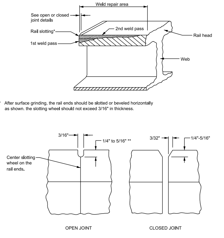
10.2 Slot rail ends on crosses, and anywhere that pounding takes place, to allow room for weld metal to flow as it cold works; and avoid the breaking or spalling that results. See Figure 6.
TABLE I –Electrode Materials
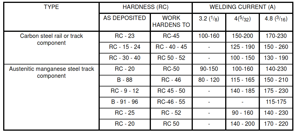
FIGURE 1 – Rail End Inspection
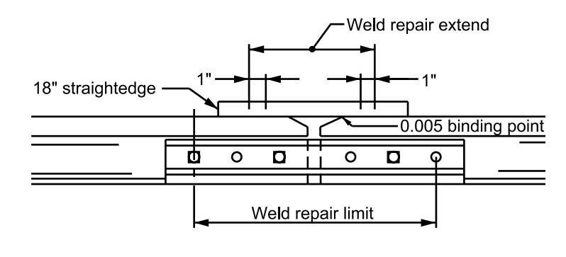
Place straight edge as show, then proceed as follows:
1. Determine whether a 0.381 mm (0.015 in) feeler gage will pass between straightedge and rail.
2. If the 0.381 mm (0.015 in) feeler gage passes under the straightedge, use a 0.127 mm (0.005 in) feeler gage to determine the required length of surface built-up. Actual weld repair area will extend 25.4 mm (1 in) on either side of the 0.127 mm (0.005 in) binding point (see weld repair extent above).
FIGURE 2 – Rail End Preparation
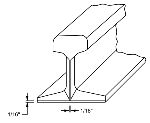
FIGURE 3 – Rail Butt Joint

FIGURE 4 – Weld Bead Patterns for Battered Rail End Buildup
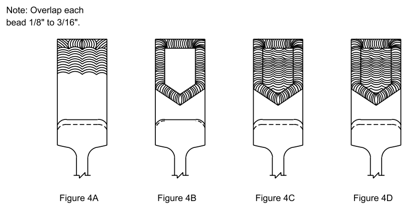
FIGURE 5 – Switch Point Detail
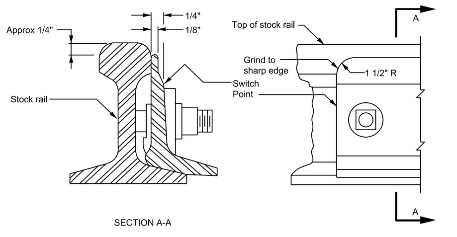
FIGURE 6 – Typical Rail Repair with Slotted Rail End
