Below is the big picture of UTRAN protocols.
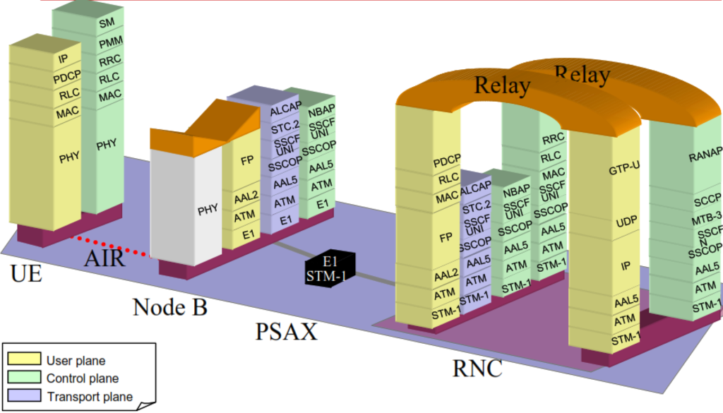
The Uu Interface in 3G/UTRAN.
The Uu interface in 3G (specifically within the UTRAN, or UMTS Terrestrial Radio Access Network) refers to the radio interface between the User Equipment (UE) and the NodeB (the 3G equivalent of a base station). It includes following protocols.
- Physical Layer (PHY): Manages the modulation, coding, and transmission of data over the air.
- Medium Access Control (MAC): Controls access to the shared radio channel.
- Radio Link Control (RLC): Ensures reliable data transfer through error correction.
- Packet Data Convergence Protocol (PDCP): Provides header compression and security through encryption.
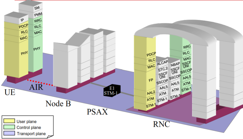
3G/UTRAN Radio Protocol Architecture.
Radio Protocol Architecture in mobile networks, such as 3G, LTE and 5G, involves a layered structure that handles communication between the User Equipment (UE) and the network. This architecture is designed to efficiently manage data transmission, control signaling, and resource allocation. Below picture represent radio protocol architecture.
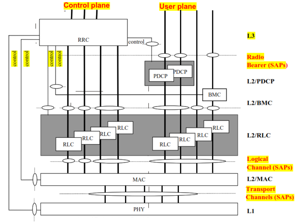
Logical/ transport / physical channel mapping.
In 3G, UTRAN, data and control information are transmitted through various channels. These channels are categorized into three types: logical, transport, and physical channels. Each type has a specific role and maps onto the others to facilitate efficient data transfer.
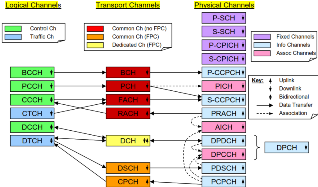
Mapping of Logical, Transport, and Physical Channels in 3G/UTRAN
Logical Channels
Logical channels define the type of data being transmitted. They are categorized into control channels and traffic channels:
- Control Channels:
- BCCH (Broadcast Control Channel): Carries system information.
- PCCH (Paging Control Channel): Used for paging messages.
- CCCH (Common Control Channel): Used for transmitting control information for connection establishment.
- DCCH (Dedicated Control Channel): Carries dedicated control information between the UE and the network.
- Traffic Channels:
- DTCH (Dedicated Traffic Channel): Carries dedicated user data.
- CTCH (Common Traffic Channel): Used for transmitting common user data.
Transport Channels
Transport channels define how data is transmitted over the radio interface. They include:
- BCH (Broadcast Channel): Used for system information broadcast.
- PCH (Paging Channel): Used for paging information.
- FACH (Forward Access Channel): Carries control or user data in the downlink.
- RACH (Random Access Channel): Used by UE to initiate communication.
- DCH (Dedicated Channel): Carries dedicated user data and control information.
- DSCH (Downlink Shared Channel): Carries user data and control information shared by multiple UEs.
Physical Channels
Physical channels correspond to the actual transmission of data over the air interface:
- P-CCPCH (Primary Common Control Physical Channel): Carries BCH.
- S-CCPCH (Secondary Common Control Physical Channel): Carries FACH and PCH.
- PRACH (Physical Random Access Channel): Carries RACH.
- DPCH (Dedicated Physical Channel): Carries DCH.
- PDSCH (Physical Downlink Shared Channel): Carries DSCH.
Mapping of Channels
1. Logical to Transport:
- BCCH maps to BCH.
- PCCH maps to PCH.
- CCCH maps to RACH (uplink) and FACH (downlink).
- DCCH maps to DCH.
- DTCH maps to DCH or DSCH.
- CTCH maps to FACH.
2. Transport to Physical:
- BCH maps to P-CCPCH.
- PCH maps to S-CCPCH.
- FACH maps to S-CCPCH.
- RACH maps to PRACH.
- DCH maps to DPCH.
- DSCH maps to PDSCH.
RRC Connected Mode and Signaling Connection.
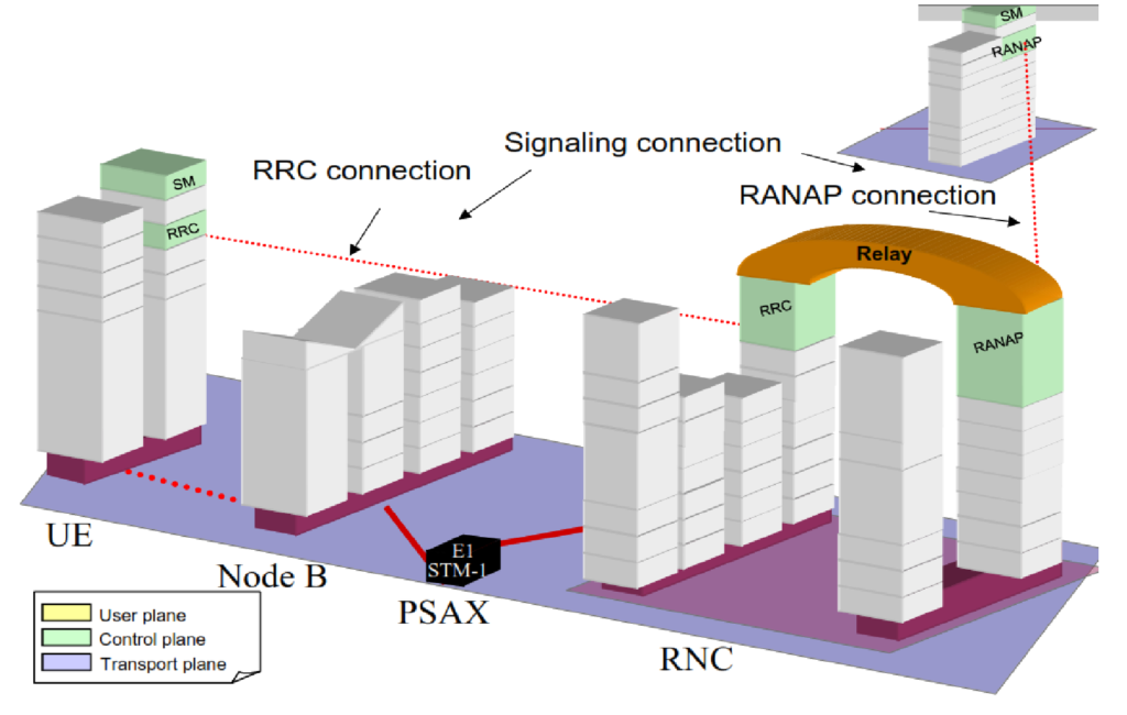
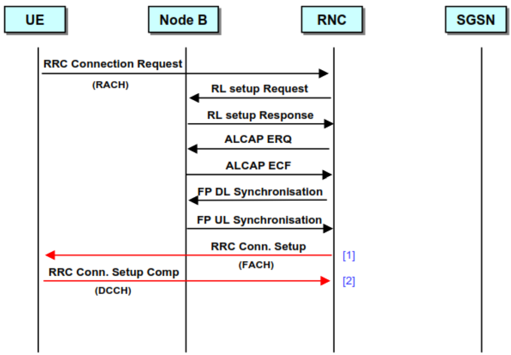
RRC connection establishment 1.
RRC Connection Setup: RRC:RRC Connection Request.
This message is sent by the UE in order to establish a RRC connection. Once RRC connected, the UE can use the signalling connection to carry out the necessary mobility procedures for call set-up.
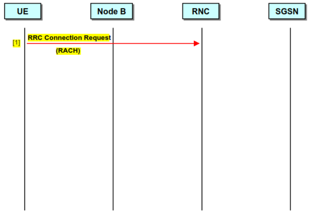
RRC connection establishment 2.
RRC Connection Setup: NBAP: Radio Link Set-up Request / Response.
On reception of the RRC Connection Request, the RNC initiates its setup by requesting the Node B to configure a Radio Link. The Node B sets up the Requested Link (DCCH) and returns a setup response indicating the Link configuration and the Binding ID.
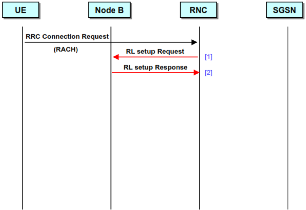
RRC connection establishment 3.
RRC Connection Set-Up: ALCAP: Establish Request / Confirm.
Once the Radio Link has been configured in the Node B, the RNC sets up an AAL2 bearer to carry it. This is done using the services of ALCAP. The RNC sends an Establish Request to the NodeB, providing details of the bearer configuration and the Link identifiers.
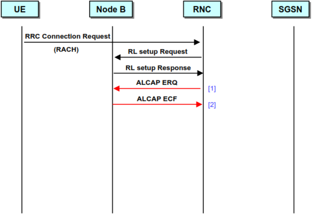
RRC connection establishment 4.
RRC Connection Set-Up: FP: DL / UL Synchronisation.
Before use, the new DCCH needs to be synchronised. This procedure allows the RNC to calculate and adjust for timing delays in the DL direction.

RRC connection establishment 5.
RRC Connection Set-Up: RRC: Connection setup/ Complete.
Once the UTRAN resources are configured, the RNC can instruct the UE to setup the RRC
connection and move from RACH/FACH to DCCH. This is done via a RRC Connection
set-up message sent on the FACH. The UE responds with a set-up complete on the new DCCH.
Signaling radio bearer configuration at the UE.

Radio Access Bearer establishment.
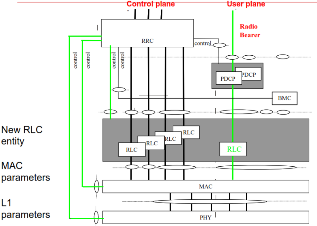
- A Radio Access Bearer Establishment is initiated when the RRC layer in the network sends a RADIO ACCESS BEARER SETUP message to its peer entity.
- This message contains L1, MAC and RLC parameters and in the synchronised case an activation time.
- RRC on the UE side then configures L1 and MAC and creates a new RLC entity associated with the new radio access bearer.
- A similar reconfiguration is also done on the network side.
- The UE then sends a RADIO ACCESS BEARER SETUP COMPLETE message back to the network.
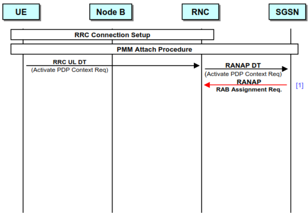
Radio Access Bearer establishment 1.
PDP Context Activation: RANAP: RAB Assignment Request.
Upon receiving the request, the SGSN initiates the setup of the Dedicated Traffic Channel (DTCH) required for the context. It does this by sending a Radio Access Bearer (RAB) assignment request to the RNC, indicating the RAB configuration and providing the uplink GTP (GPRS Tunneling Protocol) tunnel parameters.
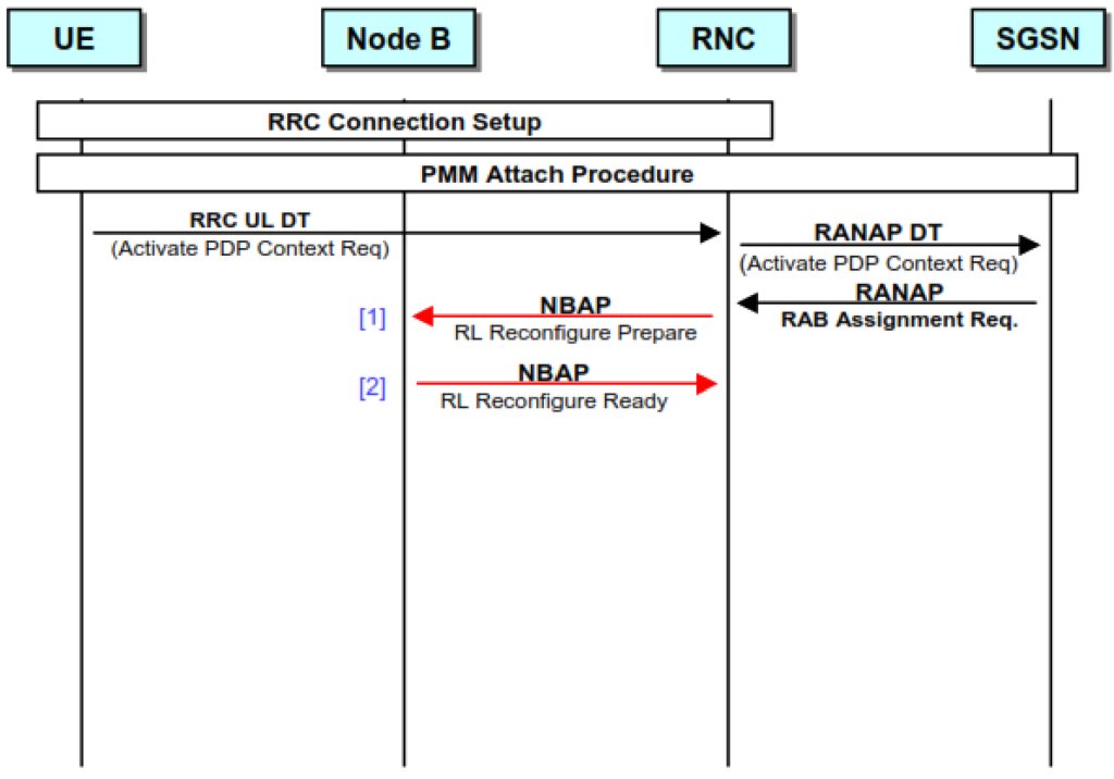
Radio Access Bearer establishment 2.
PDP Context Activation: NBAP: RL Reconfigure Prepare / Ready.
Since the UE already has a Radio Link setup, this procedure requires the addition of a DTCH to the configuration. Therefore, the RNC sends a Radio Link (RL) Reconfigure Request to the Node B. The Node B responds with an RL Reconfigure Ready, acknowledging the request but not yet implementing the changes.
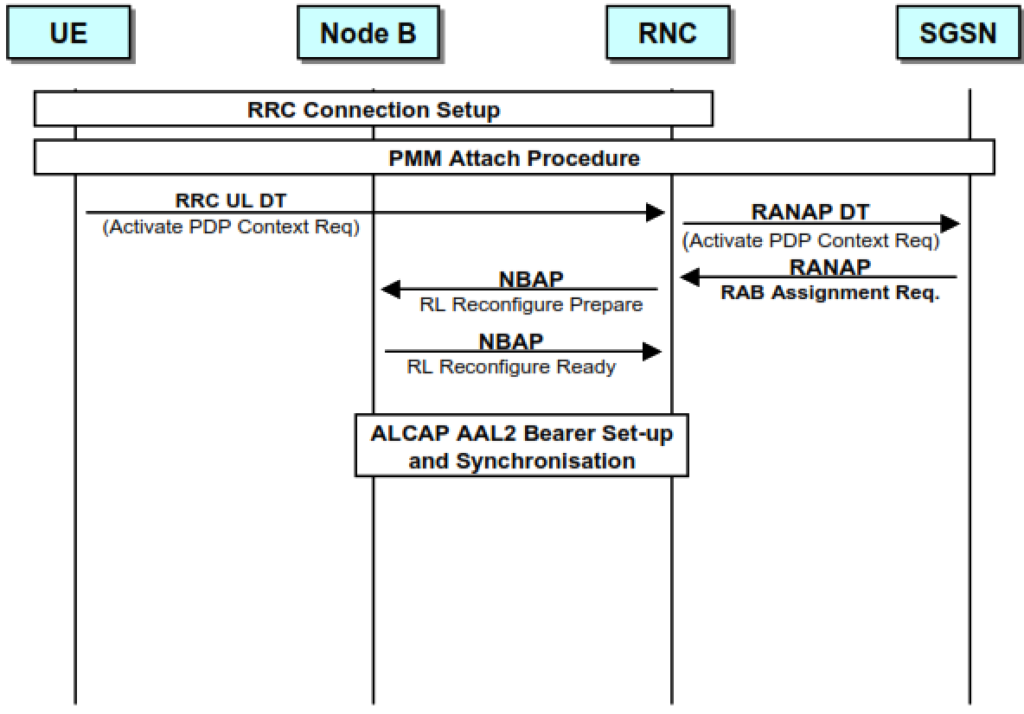
Radio Access Bearer establishment 3.
PDP Context Activation: ALCAP: AAL2 Bearer Set-Up.
Once the Radio Link (RL) has been reconfigured in the Node B, the RNC sets up the AAL2 bearer to carry the traffic. This is accomplished via ALCAP (Access Link Control Application Part) Establish procedures. Following this, Frame Protocol (FP) synchronization is carried out to ensure proper timing and coordination between the RNC and the Node B.
Radio Access Bearer establishment 4.
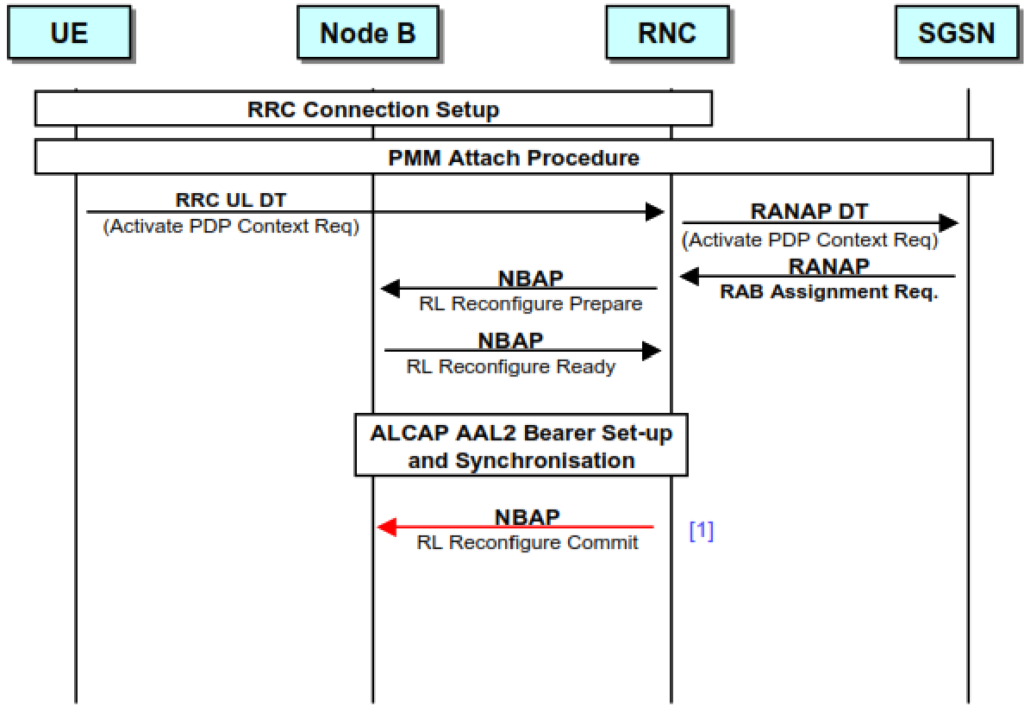
PDP Context Activation: NBAP: RL Reconfigure Commit
When the AAL2 connection is ready, the RNC instructs the Node B to commit the changes prepared during the reconfiguration. The Commit message includes the specific Frame number at which the changes should take effect, ensuring precise synchronization and seamless implementation of the new configuration.
Radio Access Bearer establishment 5.
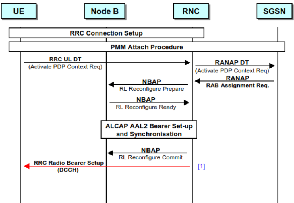
PDP Context Activation: RRC: Radio Bearer Setup.
The UTRAN has been configured for the new DTCH, allowing the UE to set up the Radio Bearer. The RNC accomplishes this via an RRC Radio Bearer (RB) Setup Request, which includes the same Connection Frame Number (CFN) indicated to Node B. This ensures synchronization between the UE and the network for the new DTCH configuration.
Radio Access Bearer establishment 6.
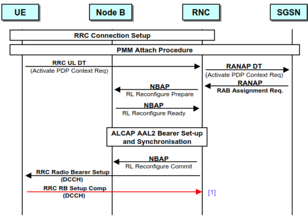
PDP Context Activation: RRC: Radio Bearer Set-Up Complete.
After the UE configures the RB, it sends a confirmation message in the form of an RRC RB setup Complete.
Radio Access Bearer establishment 7.
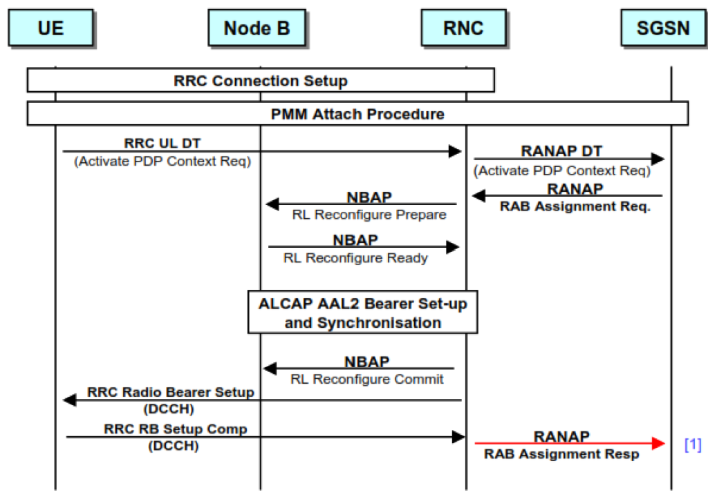
PDP Context Activation: RANAP: RAB Assignment Response.
Upon receiving the setup complete message, the RNC indicates to the SGSN that the RAB assignment procedure is complete via a RANAP RAB assignment response, which also includes the DL addressing for the GTP-U connection.
Radio Access Bearer configuration at the UE.
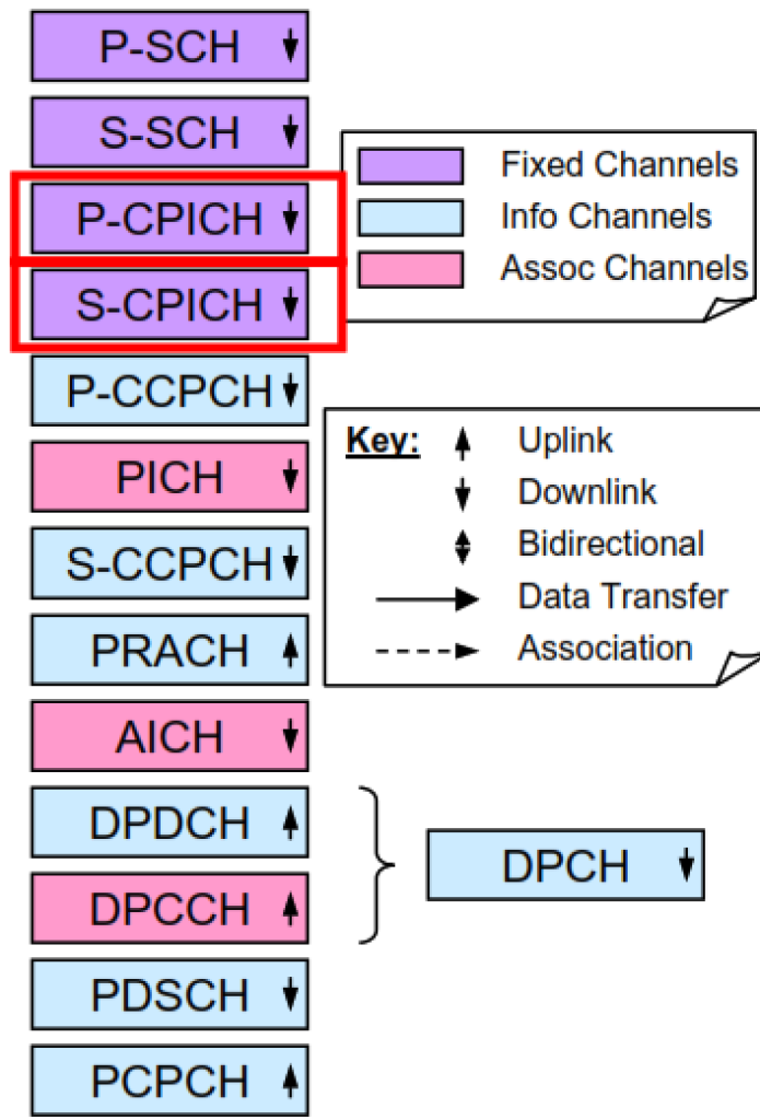
Downlink physical channel tasks.
Common Pilot Channel(CPICH)
- this is a fixed rate (30 kbit/s, SF = 256) downlink physical channel.
- Used as a phase and power reference for the other downlink physical channels.
- Primary Common Pilot Channel must always be present.
- One or several Secondary Common Pilot Channels may be present.
3-4 Signaling radio bearers per RRC connection.
3 or 4 signaling radio bearers may be set up per RRC connection.
- 2 signaling radio bearers for transport of RRC generated signaling messages.
- Transferring messages through an RLC UM entity and
- Transferring messages through an RLC AM entity.
- 1 signaling radio bearer for transferring NAS messages set to “high priority” by the higher layers(RLC AM).
- An optional 1 signaling radio bearer for transferring NAS messages set to “low priority” by the higher layers (RLC AM).
- Subsequent to the establishment of the signaling connection zero to several signaling radio bearers may be set up for transferring RRC signaling messages using transparent mode RLC (RLC TM entity).
Test your Understanding about this topic.
What kind of channel is the FACH?
Which channel carries the pilot?
What is the consequence of cell breathing?
Where is the NBAP terminated?
Order the stages of the call setup process.
RRC Connection Setup Request: The UE sends this request to the network to establish an RRC connection.
Radio Link Setup Request: This step involves setting up the radio link between the UE and the network, typically handled by the Node B and RNC.
Activate PDP Context Request: The UE sends this request to establish a Packet Data Protocol (PDP) context, allowing for data services over the network.