HARQ Concepts
HARQ (Hybrid Automatic Repeat Request) is a key technique in communication systems designed to ensure accurate data transmission by combining two methods: Forward Error Correction (FEC) and Automatic Repeat Request (ARQ).
- FEC: Before sending data, it is encoded with extra bits that help the receiver detect and fix errors that might occur during transmission. These added bits are used to correct errors without needing to resend the data.
- ARQ: This method checks if the received data is error-free using a process called Cyclic Redundancy Check (CRC). If errors are found, the receiver requests that the sender retransmit the data until it is received correctly.
In the 5G NR HARQ process, data is first encoded using FEC, which adds bits that can correct errors. When the receiver gets the data, it uses these bits to fix any mistakes. If the errors are too severe to be fixed by FEC alone, the ARQ process is triggered, and the receiver asks for the data to be sent again. This cycle continues until the data is received accurately.
HARQ is advantageous because it balances the need for error correction with the computational demands of encoding and decoding. While FEC alone can correct errors without needing retransmissions, it requires significant processing power. By combining FEC with ARQ, HARQ improves data transmission efficiency.

A notable feature of HARQ is “soft combining.” Unlike ARQ, which discards packets with errors, HARQ retains these packets. The receiver stores them and combines their useful parts with new retransmissions, enhancing the likelihood of correctly decoding the data. This method boosts the reliability of data transmission.
HARQ Mechanism.
HARQ (Hybrid Automatic Repeat Request) works through a process involving data transmission, reception status reporting, and possible data retransmission. This mechanism ensures reliable communication by following a systematic approach.
1. HARQ Process.
5G NR HARQ uses a “stop-and-wait” protocol. Here’s how it works: the sender transmits a block of data and then stops to wait for feedback from the receiver. The receiver checks the data and sends back a response—either an acknowledgment (ACK) if the data is correct or a negative acknowledgment (NACK) if there are errors.

In this process, the sender will not continue sending more data until it receives feedback for the previous transmission. This wait time, however, can reduce data throughput because the sender is idle while waiting for the receiver’s response. To counter this, HARQ uses multiple “stop-and-wait” processes simultaneously. While one process is waiting for feedback, others can continue sending or receiving data. These multiple processes are managed within what’s called a HARQ entity, with each carrier (uplink or downlink) having its own HARQ entity. According to the 3GPP standards, a HARQ entity can support up to 16 parallel processes.
Configuration of HARQ Processes
For downlink communication, the base station can configure the maximum number of HARQ processes for a UE based on network deployment, with options ranging from 2 to 16 processes. If not specifically set, the default maximum is 8 processes. In uplink communication, each carrier supports a maximum of 16 HARQ processes.
HARQ Feedback
Each 5G NR HARQ process has its feedback mechanism. After receiving data, the receiver sends back a feedback signal—an ACK if the transmission was successful or a NACK if it wasn’t. Based on this feedback, the sender decides whether to retransmit the data. This feedback is crucial as it helps maintain the reliability of data transmission, ensuring that any errors are promptly addressed.

To ensure smooth communication in HARQ, the receiver needs to know which HARQ process a transmitted Transport Block (TB) belongs to, especially since multiple processes are running in parallel. Each HARQ process is given a unique number or ID. The gNodeB (base station) informs the User Equipment (UE) of the HARQ process ID using four bits in the Downlink Control Information (DCI). This ID helps the UE identify the correct process for both uplink and downlink transmissions.
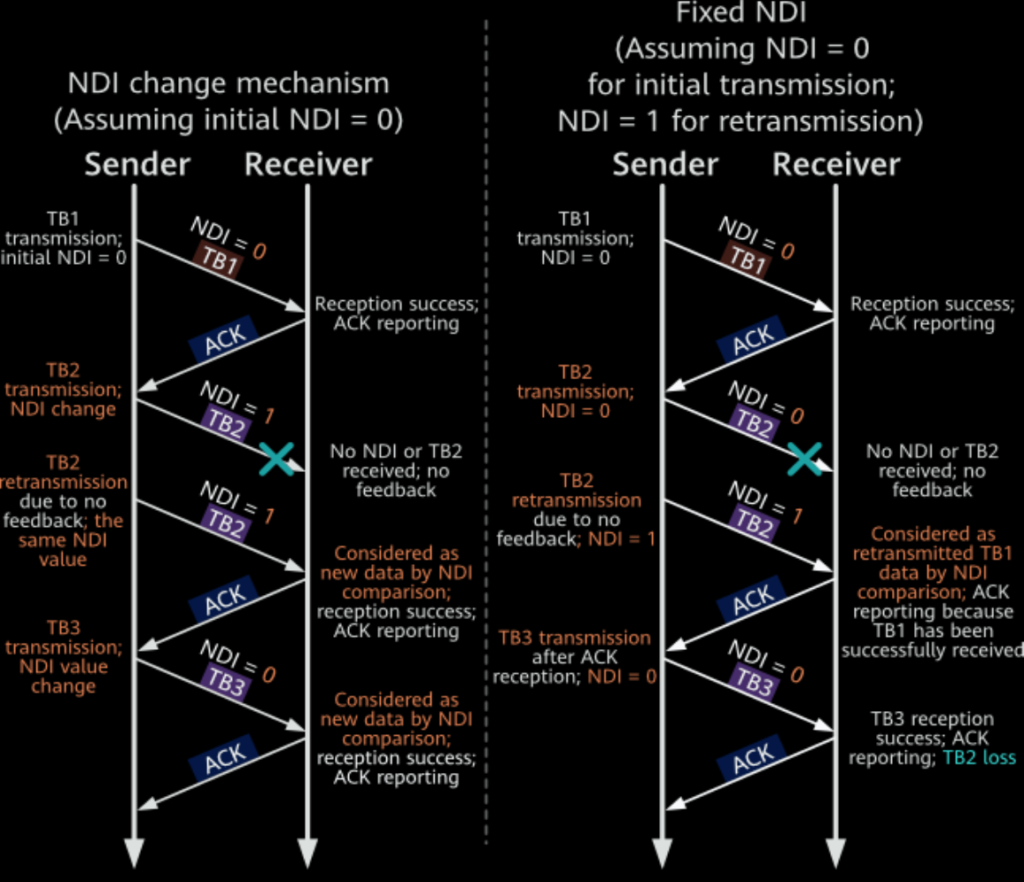
Another important aspect is determining whether the received TB is an initial transmission or a retransmission. This is managed by the New Data Indicator (NDI), another field in the DCI. The NDI can either be 0 or 1, and this value is associated with each HARQ process. The sender informs the receiver whether the transmission is new or a retransmission by either changing or retaining the NDI value.
For example, in a new HARQ process numbered 0, if the initial NDI is set to 0 and the sender transmits a new TB (let’s call it TB0), the receiver checks the NDI. If the receiver doesn’t receive TB0 correctly (as indicated by a NACK), the sender retransmits TB0 with the same NDI of 0. This helps the receiver recognize that this is a retransmission of TB0.
If the receiver successfully receives TB0 (indicated by an ACK), the sender then transmits a new TB with a different NDI value, typically 1. This change in NDI informs the receiver that the new TB is different from the previously transmitted one and is not a retransmission.
The reason for changing the NDI value instead of keeping it constant (0 for initial transmission and 1 for retransmission) is to prevent errors in identifying data transmissions. If a fixed NDI value were used, and the initial transmission was missed, the receiver might incorrectly identify all subsequent transmissions as retransmissions, leading to errors and repeated unnecessary transmissions. By changing the NDI, the system reduces the chance of such mistakes, ensuring that the receiver can accurately distinguish between new data and retransmissions.
For instance, if the receiver fails to receive TB2 during its initial transmission, the sender will retransmit TB2 with a changed NDI value. This change allows the receiver to recognize that TB2 is different from any previous TBs like TB1, avoiding confusion and ensuring proper data reception.
2. CBG-based Transmission in NR Systems.
In NR (New Radio) systems, where data transmission rates can reach several gigabits per second, a single transport block (TB) may consist of hundreds of code blocks (CBs). If the 5G NR HARQ feedback is based on the entire TB, any error in decoding will require retransmitting the entire TB, even if only a few CBs contain errors. This approach is inefficient and wastes resources, similar to reshipping an entire furniture set because of one damaged part instead of just replacing the faulty piece.
To optimize this, NR systems can transmit data in smaller units called code block groups (CBGs). Instead of retransmitting the whole TB, the receiver only asks for the retransmission of the specific CBGs that failed to decode correctly. This approach reduces the amount of data that needs to be resent, minimizing retransmission overhead. However, CB-based feedback can increase control signaling overhead because a TB consists of multiple CBs.
To balance these considerations, NR introduces CBG-based retransmission. In this method, CBs are grouped into CBGs, and feedback is provided at the CBG level. Only the CBGs with decoding errors are retransmitted, making the process more efficient in terms of resource usage than TB-based retransmission. At the same time, it requires less signaling overhead compared to CB-based feedback.
According to 3GPP TS 38.331, a TB can be divided into 2, 4, 6, or 8 CBGs depending on the number of CBs during initial transmission. This division is indicated to the user equipment (UE) using the higher layer parameter maxCodeBlockGroupsPerTransportBlock. Once the division is done, the mapping between each CBG and its CBs remains fixed, ensuring consistent and accurate retransmissions.

The receiver can first determine the number (M) of CBGs in a TB as follows:
M = min(N,C)
In the preceding formula, N is the maximum number of CBGs configured by using higher layer signaling, and C is the number of CBs in the TB.
Then, based on the relationship between M and C, the number of CBs in each CBG is determined as follows:
- M = C: One CBG includes one CB.
- M ≠ C: The number of CBs in a CBG and each specific CB in this CBG are calculated as follows:
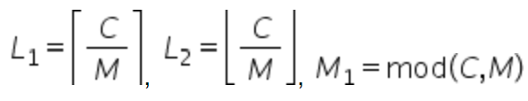
- The mth CBG (where m = 0, 1, …, M1 – 1) contains the CB(s) numbered (m x L1 + l) (where l = 0, 1, …, L1 – 1).
- The mth CBG (where m=M1, M1 + 1, …, M – 1) contains the CB(s) numbered M1 x L1 + (m – M1) x L2 + l (where l=0, 1, …, L2 – 1).
For example, assuming that N is 4 and C is 5: M = min(4,5) = N = 4. In this case: M ≠ C, L1 = 2, L2 = 1, M1 = 1
- CBG0 contains the CBs numbered 0 and 1.
- CBG1 contains the CB numbered 2.
- CBG2 contains the CB numbered 3.
- CBG3 contains the CB numbered 4.
The New Data Indicator (NDI) is used to indicate whether the TB contains new data or retransmitted data. When CBG-based retransmission is used:
- If the NDI indicates initial transmission, the receiver assumes all data is new.
- If the NDI indicates retransmission, the receiver determines which CBGs are being retransmitted based on the code block group transmission information (CBGTI) field in the downlink control information (DCI). The receiver also checks whether the buffered content of the corresponding CBGs can be reused using the code block group flushing information (CBGFI) field.
The CBGTI field specifies which CBGs are being transmitted, with each bit corresponding to a CBG (e.g., 0 means not transmitted, 1 means transmitted). The CBGFI field indicates whether the buffered content should be cleared or combined with the new transmission. If CBG-based retransmission isn’t used, both the CBGTI and CBGFI fields in the DCI are empty.

3. HARQ Feedback.
HARQ feedback involves the gNodeB receiving status reports from the UE, indicating whether data was correctly received. There are three possible feedback statuses:
- ACK (Acknowledgment): When the UE successfully receives data without errors, it sends feedback with a bit value of 1 to the gNodeB. This means the transmission was successful, and no further action is needed.
- NACK (Negative Acknowledgment): If the UE detects errors in the received data, it sends feedback with a bit value of 0 to the gNodeB, indicating that the transmission failed. The gNodeB will then retransmit the data.
- DTX (Discontinuous Transmission): When the UE fails to send any feedback to the gNodeB, it implies that the transmission failed. This can occur due to various issues like poor signal quality.
In downlink transmissions, the UE is responsible for sending HARQ feedback to the gNodeB. However, in uplink transmissions, the gNodeB itself acts as both the receiver and the scheduler. If the gNodeB detects an error during decoding, it directly commands the UE to retransmit the data, making HARQ feedback from the UE unnecessary.
The timing of when the UE should send HARQ feedback is determined by the gNodeB, using a specific field called the 5G NR HARQ feedback timing indicator (K1) in the DCI. K1 sets a delay (in slots) between when the UE receives data (PDSCH) and when it sends the corresponding feedback. For example, if the UE receives data in slot n, it will send HARQ feedback in slot (n + K1). This feedback is sent using either the PUCCH or PUSCH.

The length of the HARQ feedback timing indicator field K1 is different in DCI format 1_0 and DCI format 1_1 (for details about DCI formats, see Downlink Physical Channels – Introduction to Control Channels and Signals in the technology series).
- For DCI format 1_0, the length of K1 is fixed to 3 bits, and the value range is {1, 2, 3, 4, 5, 6, 7, 8}.
- For DCI format 1_1, the length of K1 can be 0, 1, 2, or 3 bits, depending on

 is determined by the higher layer parameter dl-DataToUL-ACK with a value range of {1, 2, 3, 4, 5, 6, 7, 8}.
 is determined by the higher layer parameter dl-DataToUL-ACK with a value range of {1, 2, 3, 4, 5, 6, 7, 8}.
HARQ feedback sequences sent at the same time-domain position are referred to as a HARQ codebook (HARQ-ACK codebook). A HARQ codebook may include one or more HARQ feedbacks at the TB or CBG level. In carrier aggregation scenarios, the codebook may also include HARQ feedbacks of multiple subcarriers.

NR protocols define two HARQ codebook types: type 1 and type 2. The following describes the codebook type configurations. For details, see 3GPP TS 38.213.
Table 1- Codebook type definition
| Codebook Determination Type | Condition |
|---|---|
| CBG-based HARQ-ACK codebook determination | codeBlockGroup Transmission = ON |
| Type-1 HARQ-ACK codebook determination | HARQ-ACK-codebook = semi-static |
| Type-2 HARQ-ACK codebook determination | HARQ-ACK-codebook = dynamic orpdsch-HARQ-ACK-Codebook=enhancedDynamic-r16 |
In Type 1 HARQ codebook, once the timing indicator K1 is set by a higher layer parameter, the UE sends HARQ feedback in the current uplink slot (slot n) for all prior slots (slots n – K1) that might have transmitted data. However, there are a couple of exceptions to this rule. If the prior slots were uplink slots, no HARQ feedback is needed. Additionally, if the UE has switched Bandwidth Parts (BWP), the feedback only starts from the first downlink slot after the switching is complete. Any slots before the switching are ignored.
Consider an example with a slot configuration of 8:2 (eight downlink slots, two uplink slots). In this scenario, “D” represents downlink slots, “U” indicates uplink slots, and “S” denotes self-contained slots where both uplink and downlink transmissions occur. Assume the UE can receive data from up to three carriers simultaneously, and the possible K1 values are 1, 3, 4, and 6. The K1 value set for the primary carrier applies if there are multiple carriers.
In slot 8, the UE sends feedback for slots 2, 4, 5, and 7, even if data wasn’t received in all these slots. For Carrier 1, data is transmitted in slots 2, 4, 5, and 7, and the feedback is based on the Transport Block (TB). For Carrier 2, where up to two TBs can be transmitted, feedback for one TB is sent for slot 2, and two TBs for slot 5. For Carrier 3, where CBG-based transmission is used, four CBGs are transmitted in slot 2, and two in slot 4 (with no data in the other two CBGs).

When data on each carrier is correctly received by the UE, the 5G NR HARQ information reported in slot 8 is a combination of the feedback bit sequences from all carriers. For Carrier 1, where the UE receives only one Transport Block (TB), 1-bit HARQ feedback is generated for each downlink transmission, as shown by sequence ①.
For Carrier 2, where the UE can receive up to two TBs simultaneously, 2-bit HARQ feedback is reported for each downlink transmission. Even if only one TB is received, a NACK is reported for the bit corresponding to the missing TB. This feedback is illustrated by sequences ② and ③, where the NACK marked in red indicates no data was received.
Carrier 3 uses Code Block Group (CBG)-based transmission, with a maximum of four CBGs. This requires 4-bit HARQ feedback for each downlink transmission. If only two CBGs are received, NACKs are reported for the bits corresponding to the missing CBGs, as shown by sequences ④, ⑤, ⑥, and ⑦.
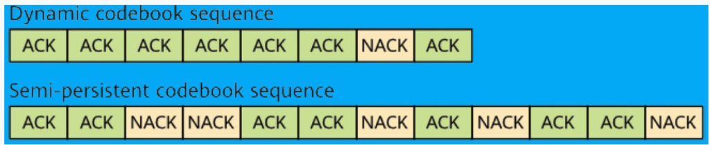
From this, we can see that Type 1 semi-persistent HARQ codebook requires a significant amount of resources. This is because HARQ feedback is required for every possible TB or CBG, regardless of whether data was transmitted. For example, in the figure, the Type 1 codebook contains 28 bits (7 sequences of 4 bits each), but only 13 of these bits have valid feedback information.
Type 2, on the other hand, is a dynamic HARQ codebook. Unlike the semi-persistent Type 1, Type 2 allows the UE to send HARQ feedback only where data transmission occurred, making the codebook size dynamic based on the number of scheduled carriers, TBs, or CBGs. In the scenario shown, only 13 bits of HARQ feedback (corresponding to the ACKs marked in black) would need to be reported using a Type 2 codebook.
The dynamic Type 2 codebook significantly reduces resource consumption if the DCI (Downlink Control Information) is received correctly. However, if the DCI reception is abnormal, the HARQ feedback from the UE might not match the number of TBs or CBGs transmitted by the gNodeB, leading to issues with feedback accuracy.
To mitigate this, NR protocols introduce the Downlink Assignment Index (DAI) field. The DAI field helps the UE identify how many pieces of 5G NR HARQ feedback need to be sent. The DAI is composed of two parts:
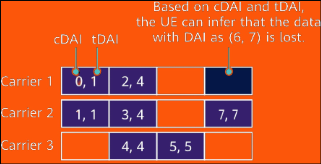
- Counter DAI (cDAI): Indicates the number of TB or CBG transmissions from the DCI reception time to the current time for downlink scheduling, first counted by carrier and then by time.
- Total DAI (tDAI) in Carrier Aggregation: Reflects the total number of downlink transmissions on all carriers up to the current time.
Both cDAI and tDAI are represented as 2-bit loopback values, using the decimal value modulo 4 in signaling.
For example, in a scenario where each slot transmits a TB (as illustrated in the figure), if the DAI value is (5, 5), it indicates that the sixth piece of data is being transmitted in the current slot and a total of six pieces have been transmitted. If the DAI value is (7, 7), the eighth piece is being transmitted, and eight pieces have been transmitted in total. If a packet loss occurs on Carrier 1, the UE can deduce from the tDAI that it needs to provide feedback for eight pieces of data, and from the cDAI that the seventh piece was lost.
In the example shown in Figure 10, the dynamic codebook includes eight pieces of HARQ feedback information. If the semi-persistent codebook is used, 12 pieces of HARQ feedback information need to be sent regardless of the amount of transmitted information, as shown in Figure 11.
4. HARQ Type
HARQ (Hybrid Automatic Repeat reQuest) can be classified based on how retransmissions are handled in both the time domain and frequency domain.
Time-Domain HARQ: Synchronous vs. Asynchronous
Synchronous HARQ: In this method, retransmissions occur at a fixed time interval after the initial transmission. This means that each HARQ process is tied to a specific time slot, making it predictable when a retransmission will occur. One key advantage of synchronous HARQ is that the HARQ process ID can be derived directly from the system subframe number, eliminating the need for additional signaling to indicate the process ID.
Asynchronous HARQ: Here, retransmissions can happen at any time after the initial transmission, and 5G NR HARQ processes can be used in any order. This allows for more flexible scheduling of retransmissions, accommodating varying network conditions. However, asynchronous HARQ requires additional control signaling, as the sender must indicate the process number to the receiver to manage the HARQ processes correctly.
Frequency-Domain HARQ: Adaptive vs. Non-Adaptive
Adaptive HARQ: In adaptive HARQ, the frequency-domain resources used for retransmissions (such as Resource Block (RB) positions, the number of RBs, and Modulation and Coding Scheme (MCS) indexes) can change from those used in the initial transmission. This adaptability allows the system to respond to changing channel conditions, potentially improving the efficiency of retransmissions.
Non-Adaptive HARQ: In contrast, non-adaptive HARQ requires that the frequency-domain resources used for retransmissions remain the same as those used in the previous transmission. This approach is simpler but less flexible, as it does not account for changing channel conditions.
Application in 5G and 4G Networks
In 5G, the standard approach is to use asynchronous adaptive HARQ for both uplink and downlink transmissions. This allows for flexible and efficient management of retransmissions in the network.
In 4G, asynchronous adaptive HARQ is used in the downlink, while the uplink may use either synchronous adaptive 5G NR HARQ or non-adaptive HARQ. This difference reflects the evolution of HARQ strategies as network technology has advanced, with 5G offering greater flexibility and efficiency in handling retransmissions.
HARQ Gains.
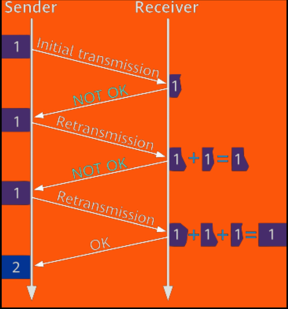
HARQ (Hybrid Automatic Repeat reQuest) offers significant advantages over traditional ARQ (Automatic Repeat reQuest), particularly through the technique known as soft combining. In ARQ, when a data packet is received with errors, the receiver discards the erroneous data and requests a retransmission. In contrast, HARQ retains the erroneous data in a buffer and combines it with the data received from the retransmission. This combined data is then decoded, which improves the chances of successful decoding. If the combined data still fails to decode correctly, another retransmission is requested, and the process of combining continues. This approach, known as soft combining, provides two main types of gains:
- Signal Energy Gain: Achieved by retransmitting the same coded bits, which increases the signal-to-noise ratio (SNR).
- Encoding Gain: Obtained by sending additional check bits during retransmissions, enhancing the reliability of decoding.
In 5G NR HARQ, the process of soft combining is implemented through two primary methods: Chase Combining (CC) and Incremental Redundancy (IR).
Chase Combining (CC)
In Chase Combining, the retransmitted data is identical to the original transmission. The sender appends a Cyclic Redundancy Check (CRC) to the original information bits, encodes them to create a coded bit set, and transmits this set during both the initial transmission and any subsequent retransmissions. This repetition increases the SNR, leading to improved decoding success rates.
Incremental Redundancy (IR)
Incremental Redundancy takes a different approach by not requiring the retransmitted data to be identical to the initial transmission. Instead, multiple coded bit sets are generated from the same information, each containing different sets of bits. When retransmission is needed, a different coded bit set, known as a redundancy version (RV), is transmitted. The receiver then combines this new set with the previously received data, accumulating redundancy information over multiple transmissions. This accumulation reduces the effective code rate, improving the likelihood of successful decoding. IR is widely used, including by companies like Huawei, to implement soft combining in NR (New Radio) systems.
Implementation of IR through FEC and Rate Matching
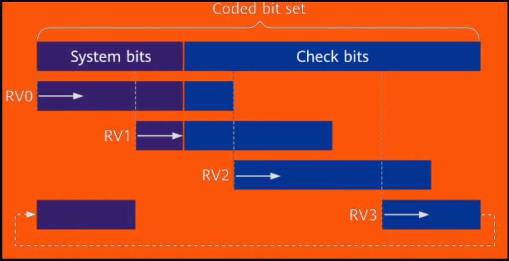
The IR technique relies on Forward Error Correction (FEC) and rate matching. The sender encodes the data using a specific algorithm, adding redundancy that includes both the system bits (actual data) and check bits (error-checking information). The resulting coded bit set is divided into four redundancy versions (RV0 to RV3) using a ring buffer, with each version having different starting positions:
- RV0: Used for the initial transmission, containing all system bits, which supports self-decoding.
- RV2, RV3, and RV1: Used for retransmissions in sequence.
- RV2 contains only check bits.
- RV3 contains mostly system bits, supporting self-decoding.
- RV1 contains a few system bits, primarily check bits, and does not support self-decoding.
NR protocols define start position k0 of each RV. For details, see “Table 5.4.2.1-2 Starting position of different redundancy versions, k0” in 3GPP TS 38.212.