In LTE, the transmission bandwidth on the UE side must be the same as that configured on the eNodeB side. However, 5G NR supports larger transmission bandwidths than those in LTE, which results in a higher cost of UEs if they should support equivalent transmission bandwidths. In addition, 5G supports a variety of services and some services from certain UEs may not require a large transmission bandwidth. Therefore, the concept of BWP is proposed for 5G NR in 3GPP specifications.
A BWP is a segment of continuous spectrum resources to be used by a UE for data transmission, and is configured by the network. A BWP can be smaller than the maximum transmission bandwidth on the network side, allowing for flexible transmission bandwidth configurations. It should be noted that as BWP is a UE-level concept, different BWPs may be configured for different UEs.
Application Scenarios of BWP
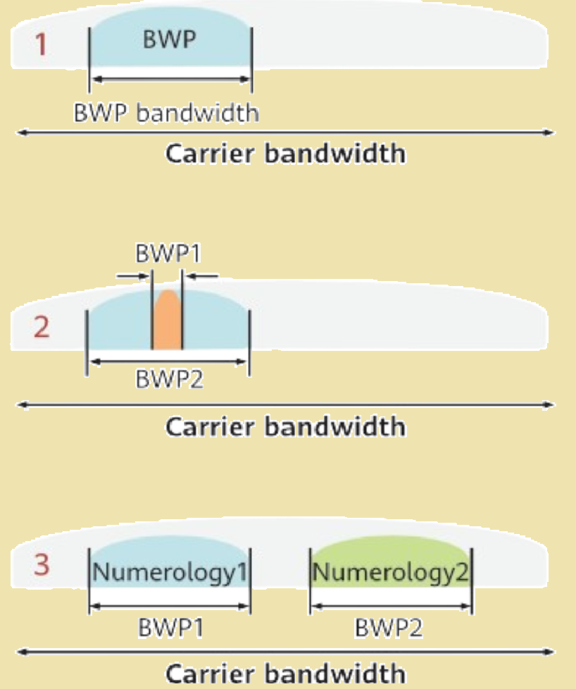
The application scenarios of BWP are as follows:
- Scenario 1: A UE supporting small bandwidths can access a large-bandwidth network, reducing UE costs.
- Scenario 2: A UE can switch between large and small BWPs to save power.
- Scenario 3: Different numerologies can be configured for different BWPs to carry different services.

BWP Classification.
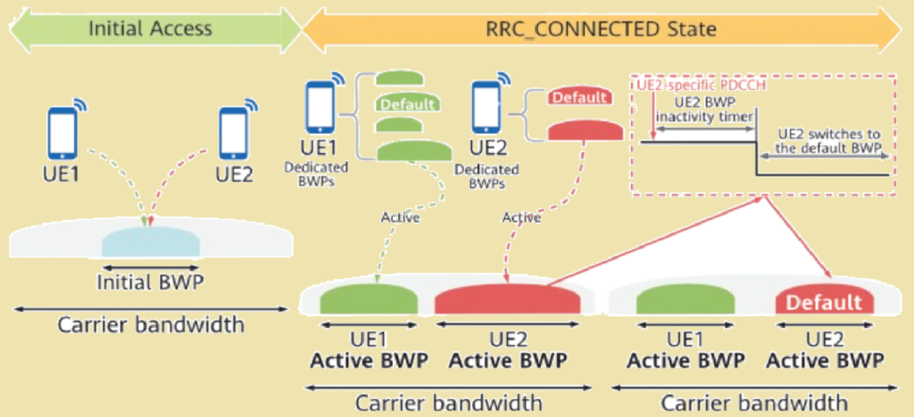
Based on the access status of a UE, BWPs can be categorized as initial BWPs and dedicated BWPs.
- An initial BWP is used for data transmission of the UE during initial access.
- A dedicated BWP is used for data transmission if the UE is in the RRC_CONNECTED state.
In terms of transmission direction, BWPs (including initial BWPs and dedicated BWPs) can be divided into downlink (DL) BWPs and uplink (UL) BWPs.
According to 3GPP TS 38.211, a UE can be configured with four dedicated BWPs, but only one can be activated at a time as the active BWP. In addition, 3GPP TS 38.213 defines a BWP inactivity timer. When the timer expires, the gNodeB switches the BWP of a UE back to the default BWP (if configured) or the initial BWP, as shown in figure below. Both an active BWP and a default BWP are dedicated BWPs.

BWP Position.
Before a UE transmits uplink or downlink data in a specific BWP, it must obtain information about the BWP configured by the gNodeB. Because the carrier bandwidth configured on the gNodeB side is probably greater than the BWP configured for the UE, the UE needs to obtain a reference point from the gNodeB before determining the BWP. The procedures for determining the position of an initial BWP and that of a dedicated BWP are different. The following describes these procedures in SA networking.
Figure below shows the procedures used by a UE to obtain an initial BWP.

In these procedures:
- The frequency-domain position and bandwidth of an initial DL BWP is defined in the RMSI CORESET (CORESET#0) by default. Alternatively, the initial DL BWP can be indicated by the RMSI configuration. RMSI is short for Remaining Minimum System Information, which is also called System Information Block 1 (SIB1).
- In TDD, the center frequency position of an initial UL BWP is the same as that of the corresponding initial DL BWP because the uplink and downlink frequency resources are the same. The bandwidth of the initial UL BWP is indicated by the RMSI configuration.
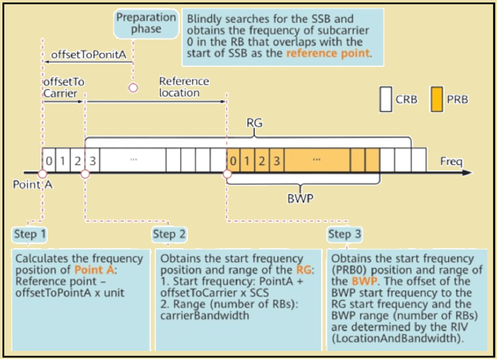
If an initial BWP is indicated by the RMSI configuration, the procedures used for a UE to obtain its position is the same as those to obtain a dedicated BWP. Figure below shows the procedures used by a UE to obtain a dedicated BWP.

- Preparation phase: The UE blindly searches for the SSB, obtains the frequency of subcarrier 0 in the RB that overlaps with the start of the SSB as the reference point, and demodulates the RMSI to obtain the offset of Point A relative to this frequency. These are the preparations for determining Point A. It is specified in 3GPP TS 38.211 that the unit of the offset is 15 kHz for FR1 and 60 kHz for FR2.
- Step 1: The UE determines the frequency-domain position of Point A.In 3GPP TS 38.211, the frequency of subcarrier 0 in CRB0 is defined as Point A. Point A can be viewed as the start point of the entire frequency domain in a 5G NR system. The UE obtains the position of Point A in either of the following ways:
- During initial access, the UE can obtain the reference point only through SSB blind detection. As such, in 3GPP TS 38.211, the frequency point of Point A is defined as follows: Frequency of the reference point – Frequency offset (offsetToPointA) x Unit.
- In scenarios other than initial access, point A is indicated by the ARFCN and sent to the UE through the RMSI message if some carriers (such as the uplink carrier in FDD mode) do not have SSBs. For details about the conversion between NR-ARFCNs and frequencies, see 3GPP TS 38.104.
- Step 2: The UE determines the frequency-domain position of the RG.As described above, an RG includes all subcarrier resources on the transmission bandwidth of a carrier. As a benchmark, Point A may be outside the frequency range of a carrier. Therefore, the start point of an RG is marked as CRBn, that is, an offset of n RBs relative to CRB0 (Point A). With Point A as the benchmark, the UE obtains the offset (offsetToCarrier), the number of RBs (carrierBandwidth), and the SCS (subcarrierSpacing) through the RMSI message to determine the specific frequency-domain position of the RG. In Figure below, offsetToCarrier = 36.
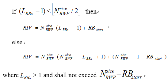
- Step 3: The UE determines the frequency-domain position of the BWP.The BWP of a UE is only part of the spectrum resources in the RG in the frequency domain. Therefore, the start CRB (CRB3 in the figure) of the RG is used as the benchmark. The UE obtains the offset of PRB0 relative to the benchmark and the number of RBs through the RMSI message to determine the BWP position. Different from the method used to determine the RG position, the offset and the number of RBs used to determine the BWP are obtained by parsing the resource indicator value (RIV). In 3GPP TS 38.331, the RIV is defined as the locationAndBandwidth parameter. 3GPP TS 38.214 defines the RIV calculation method as follows:

In the formula, LRBs is the BWP size, RBstart is the offset, and NBWPsize is fixed at 275.
The UE can obtain only the RIV, and LRBs and RBstart can be obtained by performing a reverse operation on the formula.
If RIV is 16483, the values of RBstart and LRBs are 16 and 217 respectively based on the formula.
In addition, different numerologies mean different SCSs and different frequency-domain widths of RBs. Consequently, the UE also needs to obtain the SCS of a BWP from the RMSI to determine the bandwidth range of the BWP.
References.
- 3GPP TS 38.101-2, User Equipment (UE) radio transmission and reception; Part 1: Range 2 Standalone (Release 16)
- 3GPP TS 38.101-1, User Equipment (UE) radio transmission and reception; Part 1: Range 1 Standalone (Release 16)
- 3GPP TS 38.300, NR and NG-RAN Overall Description; Stage 2 (Release 16)
- 3GPP TS 38.104, Base Station (BS) radio transmission and reception (Release 16)
- 3GPP TS 38.213, Physical layer procedures for control (Release 16)
- 3GPP TS 38.211, Physical channels and modulation (Release 16)
- 3GPP TS 36.213, Physical layer procedures (Release 16)
- 3GPP TS 36.211, Physical channels and modulation (Release 14)
- 3GPP TR 38.912 (Release 15)
- 3GPP TR 38.802, Physical Layer Aspects (Release 14)
Interview Questions asked about 5G Frequency Domain Resources in telecom sector.
Q.1 What are the functions of the synchronization raster?
Q.2 Why synchronization raster is introduced to 5G NR?
Q.3 What is a bandwidth part (BWP)?
Q.4 Why are BWPs introduced in 5G NR?
Q.5 How does a UE obtain its BWP information from the network?
Q.6 What are the basic frequency domain resources in 5G NR?
Q.7 How do frequency domain resources differ from LTE?
Q.8 What are the duplex modes of the 5G NR frequency bands?
Q.9 Why does FR2 only operate in time division duplex (TDD)?