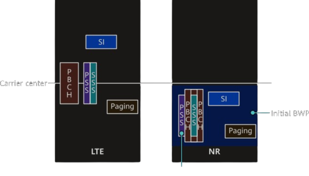
A UE receives primary synchronization signal (PSS) and secondary synchronization signal (SSS) from a cell immediately after being powered on in order to achieve downlink time synchronization with the cell in 5G NR, which is identical to the process in LTE. However, the PSS and the SSS in LTE are always located at the center of a carrier. As such, if an LTE UE obtains the PSS/SSS, the central frequency of the carrier is known.
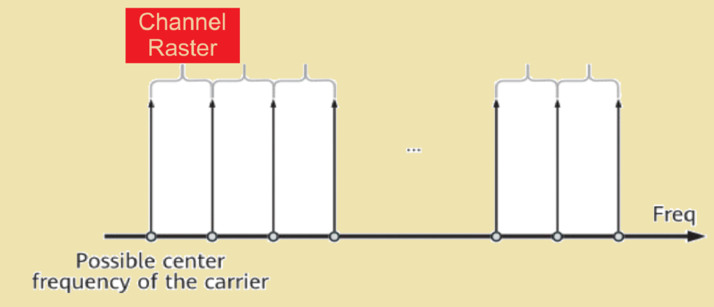
If an LTE UE does not know the frequency-domain position of a carrier, it searches for the PSS/SSS at all possible carrier positions, or on the channel raster. To better understand the channel raster, we should be aware of the following: Not every frequency can be the center frequency of a cell carrier, and there is a minimum frequency interval between two center frequencies. This interval is known as the channel raster, which is fixed to 100 kHz in LTE.

The channel raster concept in 5G NR is the same as that in LTE. However, the minimum frequency interval in some frequency bands of 5G NR is less than 100 kHz. The channel bandwidth of an NR cell may be very large. If PSS and SSS signals are located at the center of a carrier and 5G NR UEs search for these signals at a granularity of 100 kHz or less, the search will take a long time and poses high performance requirements on the UEs.
To enable UEs to quickly detect the PSS and SSS of a cell, 5G NR uses the synchronization signal and PBCH block (SSB, including the PSS, SSS, and PBCH), which, unlike LTE, is not located at the center of a carrier. There is a limited number of potential SSB positions in each frequency band, which are referred to as synchronization rasters and a UE only needs to search for SSBs at these specific positions. A synchronization raster can also be regarded as the minimum frequency interval between SSB center frequencies.
Figure below shows the positions of PSSs and SSSs in LTE and 5G NR carriers.

A synchronization raster divides a carrier bandwidth into a limited number of SSB positions, while 3GPP assigns all possible SSB center frequencies on the NR spectrum with Global Synchronization Channel Numbers (GSCNs). 3GPP TS 38.104 provides a conversion relationship between SSB center frequencies and GSCNs, as shown in Table below.
Table GSCN parameters for the global frequency raster.
| Frequency Range | SS Block Frequency Position SSREF | GSCN | Range of GSCN |
|---|---|---|---|
| 0–3000 MHz | N x 1200 kHz + M x 50 kHz,N = 1:2499, M ϵ {1, 3, 5} (Note 1) | 3N + (M – 3)/2 | 2–7498 |
| 3000–24250 MHz | 3000 MHz + N x 1.44 MHzN = 0:14756 | 7499 + N | 7499–22255 |
| 24250–100000 MHz | 24250.08 MHz + N x 17.28 MHz,N = 0:4383 | 22256 + N | 22256–26639 |
| NOTE 1: The default value for operating bands which only support SCS spaced channel raster(s) is M=3. | |||
As listed in the table, the higher the frequency range, the larger the synchronization raster. In the 24250–100000 MHz frequency range, the minimum frequency spacing between SSB center frequencies is 17.28 MHz. This is because in high frequency bands, 5G NR cells with large channel bandwidths can be deployed and large synchronization rasters are needed to ensure quick detection of SSBs by UEs.
The value of a synchronization raster may not be an integral multiple of a CRB bandwidth. Consequently, the frequency-domain start position for blind SSB detection may not be aligned with the boundary of a CRB for data transmission, as shown in Figure below. As a result, during initial access, a UE also needs to know the offset, which is broadcast by the NR cell in the MIB. In 3GPP specifications, KSSB is used to indicate the offset. (For other functions of KSSB, see 3GPP TS 38.213.) A UE can use KSSB to obtain the frequency-domain information of the CRB that overlaps with the start of the SSB, that is, the frequency point of subcarrier 0 on this CRB. This frequency point is also known as the reference point, and is required for the UE to determine Point A and further determine a BWP position.
Figure below SSB carrier position and the carrier positions of the data channel RBs.

In 3GPP TS 38.211, the value range of KSSB varies depending on the frequency range. The calculation method of a reference point is as follows:
- For FR1, the KSSB uses 15 kHz as the unit, and the value range is from 0 to 23. Frequency of the reference point = Frequency of the lowest SSB carrier – KSSB x 15 kHz.
- For FR2, KSSB uses the SCS as the unit and the value range is from 0 to 11.Frequency of the reference point = Frequency of the lowest SSB carrier –KSSB x subCarrierSpacingCommon.
References.
- 3GPP TS 38.101-2, User Equipment (UE) radio transmission and reception; Part 1: Range 2 Standalone (Release 16)
- 3GPP TS 38.101-1, User Equipment (UE) radio transmission and reception; Part 1: Range 1 Standalone (Release 16)
- 3GPP TS 38.300, NR and NG-RAN Overall Description; Stage 2 (Release 16)
- 3GPP TS 38.104, Base Station (BS) radio transmission and reception (Release 16)
- 3GPP TS 38.213, Physical layer procedures for control (Release 16)
- 3GPP TS 38.211, Physical channels and modulation (Release 16)
- 3GPP TS 36.213, Physical layer procedures (Release 16)
- 3GPP TS 36.211, Physical channels and modulation (Release 14)
- 3GPP TR 38.912 (Release 15)
- 3GPP TR 38.802, Physical Layer Aspects (Release 14).
Interview Questions asked about 5G Frequency Domain Resources in telecom sector.
Q.1 What are the functions of the synchronization raster?
Q.2 Why synchronization raster is introduced to 5G NR?
Q.3 What is a bandwidth part (BWP)?
Q.4 Why are BWPs introduced in 5G NR?
Q.5 How does a UE obtain its BWP information from the network?
Q.6 What are the basic frequency domain resources in 5G NR?
Q.7 How do frequency domain resources differ from LTE?
Q.8 What are the duplex modes of the 5G NR frequency bands?
Q.9 Why does FR2 only operate in time division duplex (TDD)?