In LTE systems, each cell is assigned a unique Physical Cell Identifier (PCI) to distinguish between different cells. Cells are organized into groups, identified by primary and secondary synchronization sequences (PSCH and SSCH). There are 168 cell groups, each containing three cells, facilitating efficient cell identification and synchronization.
PCI reuse can cause collisions and interference if the reuse distance is too small. Effective PCI planning assigns unique IDs to each cell to prevent interference, ensuring reliable UE synchronization and decoding of pilot channels in the network.
What is PCI Design?
Before accessing an LTE cell, a UE must perform time and frequency synchronization and obtain system parameters to demodulate downlink signals and transport uplink signals. LTE supports two cell search procedures:
- Initial Cell Search:
- Occurs when a UE is powered on or disconnected from the serving cell.
- UE detects an LTE cell and interprets necessary information for registration.
- Search During Handover:
- Happens after UE is connected to an LTE cell.
- When event A3 conditions are met, UE reports neighboring cell measurements to the serving eNodeB for handover.
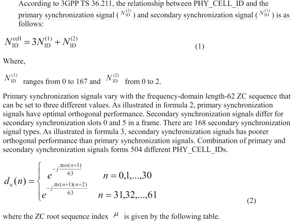

PSCH Sequence Design.
In LTE systems, the design of the Primary Synchronization Channel (PSCH) sequence is crucial for reducing inter-cell interference and enhancing synchronization performance. The system requires efficient synchronization to support features like multicast/broadcast over single frequency network (MBSFN) and inter-cell interference coordination.

Considerations for PSCH Sequence Design:
Sequence Orthogonality:
- Impact on Performance: Orthogonal sequences minimize inter-cell interference and improve PSCH performance.
- Synchronization: Cell-shared PSC provides better synchronization using cross-correlation methods compared to cell-specific PSC.
Challenges with Cell-Shared PSC:
- SFN Signals: Combining multiple PSC multi-path signals in SFN can lead to unreliable channel estimation results when using cell-shared PSC.
- Coherent Detection: Cell-shared PSC affects the coherent detection on the Secondary Synchronization Channel (SSCH), leading to issues with accurate unicast channel estimation.
Design Requirements:
- Moderate Number of PSCs: A balance is needed to ensure PSC detection performance without increasing synchronization complexity.
- Low Correlation: Minimize cross-correlation between PSCs to ensure accurate cell identification and channel estimation.
- Similar Amplitude: Ensures good channel estimation during SSCH detection.
- Low Complexity: Facilitates quick synchronization and efficient cell search.
Huawei LTE Systems:
- Uses three PSCs mapped to cell IDs.
- Employs constant amplitude zero auto-correlation (CAZAC) sequences, which provide constant amplitude in the time domain and constant envelope modulation in the frequency domain.
- PSCs are generated from frequency-domain Zadoff-Chu (ZC) sequences, ensuring low correlation with neighboring data channels and accurate channel fading estimation.
Practical Implementation:
- Sequence Generation:
- PSC sequences are derived from frequency-domain ZC sequences, which are designed to minimize interference and maintain low complexity.
- LTE standards use three length-62 ZC sequence numbers to prevent interference and reduce sequence complexity.
- Synchronization and Identification:
- PSCs are used for physical cell identity within a PHY_CELL_ID group and perform symbol, frequency, and 5-ms time synchronization.
- PSCH signals are transmitted every half-frame (5 ms) to maintain synchronization.
By following these design principles, LTE networks can achieve reliable synchronization, reduce inter-cell interference, and maintain efficient cell search and handover processes.

SSCH Sequence Design.
The Secondary Synchronization Channel (SSCH) is another an important channel in LTE (Long Term Evolution) networks, working alongside the Primary Synchronization Channel (PSC) to facilitate efficient communication between user equipment (UE) and the base station (eNodeB). The SSCH specifically aids in the detection of physical cell identity (PHY_CELL_ID) group IDs and frame timing, ensuring precise synchronization.
Functions of the SSCH.
PHY_CELL_ID Group ID Detection:
- The SSCH helps in identifying the PHY_CELL_ID group, which is essential for the UE to distinguish between different cells within the network. Each cell is assigned a unique PHY_CELL_ID, which is crucial for accurate cell selection and handover processes.
Frame Timing Detection:
- The SSCH provides the necessary timing information for frame synchronization. Accurate frame timing is vital for the UE to align its internal clock with the LTE frame structure, ensuring efficient data transmission and reception.
Sequence Structure and Design.
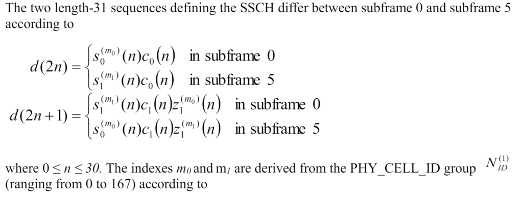
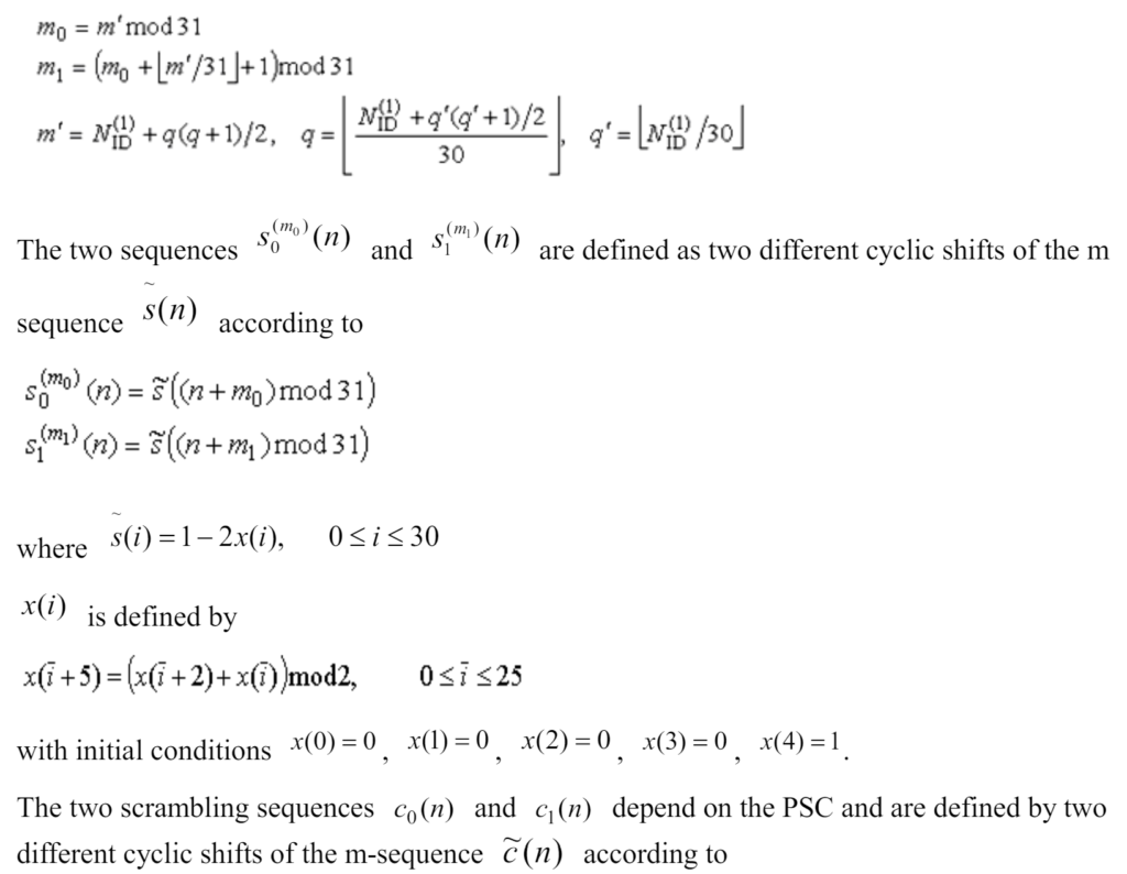
The sequence used for the SSCH is an interleaved concatenation of two binary sequences. The design of these sequences follows specific standards to minimize interference and optimize performance.
Aspects of the SSCH Sequence:
m-Sequences:
- LTE standards use m-sequences (maximum length sequences) for the design of SSCH sequences. These sequences have excellent autocorrelation properties, which help in distinguishing between different synchronization signals and reducing interference.
Cyclic Shifts:
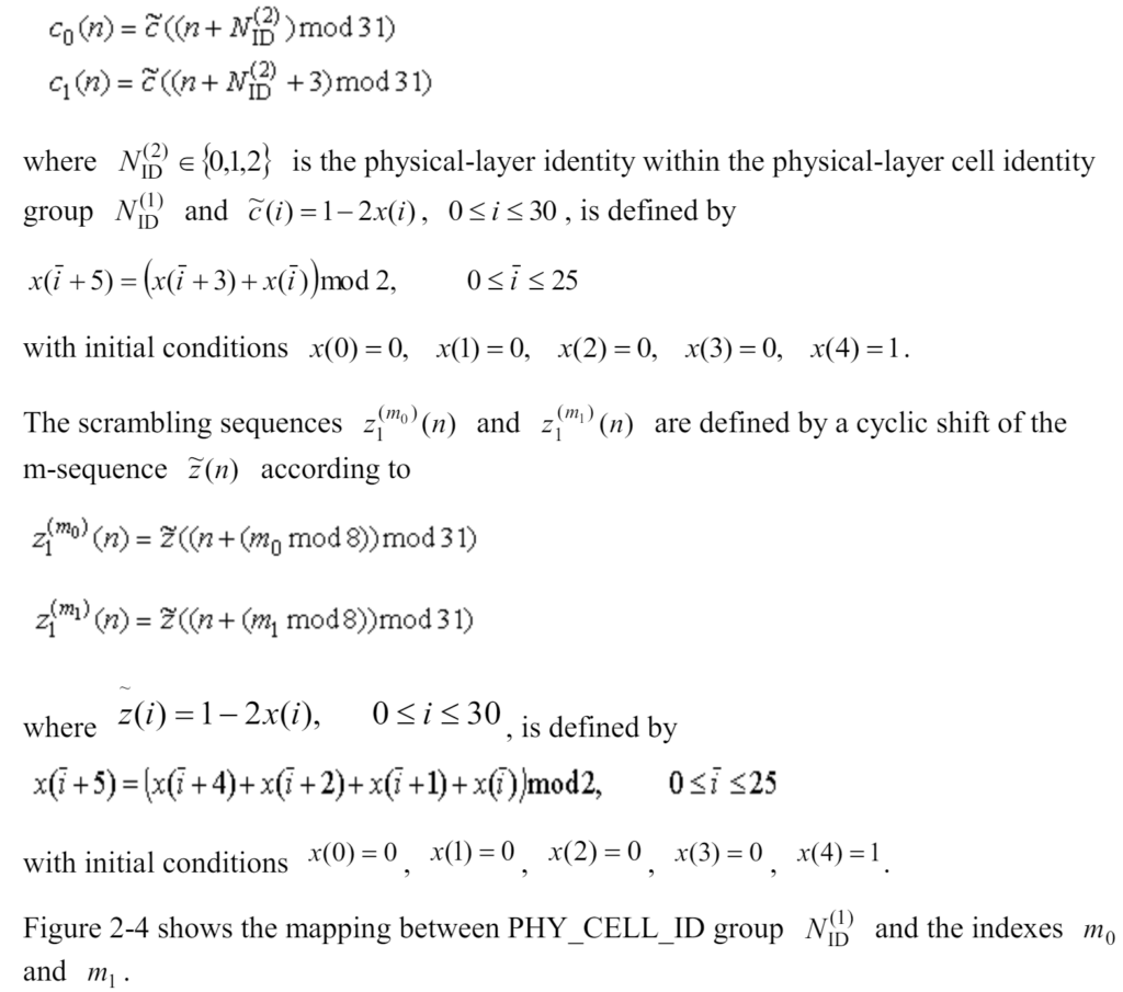
- After applying cyclic shifts, a sequence group is derived from a length-31 m-sequence. From this group, two sequences are selected to serve as the SSCH sequences.
Scrambling and PAPR Reduction:
- The selected SSCH pair scrambles a binary scrambling code corresponding to the PSC. This scrambling helps prevent inter-SSCH interference within a group and reduces the Peak-to-Average Power Ratio (PAPR), improving the robustness of the transmission.
Subcarrier Mapping:
- The SSCH sequences are alternately mapped to the 62 subcarriers used by the SSCH, ensuring they are multiplexed alternately in the frequency domain. This arrangement minimizes interference and optimizes frequency utilization.
Subframe Usage:
- In a radio frame, subframe 0 and subframe 5 use different SSCH sequences. This differentiation allows the system to detect only one SSCH to achieve frame synchronization, simplifying the synchronization process for the UE.
BPSK Constellation Mapping:
- The SSCH sequences are mapped using Binary Phase Shift Keying (BPSK) in the frequency domain. This modulation technique is shown in Figure 2-3 and provides a simple and robust method for conveying synchronization information.


Downlink Cell-Shared Pilot Design in LTE.
The downlink cell-shared pilot design includes three main types of reference signals:
- Cell-Specific Reference Signals (CRS):
- Also known as common reference signals, these are applicable to all UEs within a cell.
- They are transmitted throughout the entire cell, enabling all UEs to use them for channel estimation, demodulation, and handover processes.
- CRS assists in maintaining the overall performance and stability of the LTE network, ensuring that all UEs have a consistent and reliable reference for communication.
- UE-Specific Reference Signals (URS):
- These reference signals are transmitted only in resource elements specific to a particular UE.
- URS allows for more precise channel estimation tailored to the specific needs of an individual UE, optimizing the communication link between that UE and the eNodeB.
- This type of reference signal is particularly useful in scenarios where UEs experience varying channel conditions, enabling the network to provide more targeted and efficient support.
- MBSFN Reference Signals:
- Applicable only to Multimedia Broadcast Single Frequency Network (MBSFN) areas.
- These reference signals are used specifically for MBSFN transmissions, which involve broadcasting the same content synchronously across multiple cells.
- MBSFN reference signals ensure accurate and efficient transmission and reception of broadcast content, supporting services such as mobile TV and other multicast applications.
Modulation and Power Efficiency
All three types of downlink reference signals are modulated using Quadrature Phase Shift Keying (QPSK) mode. QPSK is a modulation scheme that offers several advantages, particularly in the context of reference signals:
- Low Peak-to-Average Power Ratio (PAPR):
- QPSK modulation results in a lower PAPR, which is beneficial for the power amplifiers used in the transmission process. A lower PAPR reduces the stress on power amplifiers, enhancing their efficiency and longevity.
- Power Amplifier Requirements:
- By using QPSK modulation, the requirements for power amplifiers are reduced. This leads to more efficient power usage and can result in cost savings for network operators.
Importance of Reference Signals.
Reference signals are crucial for several key functions in LTE networks:
- Channel Estimation:
- UEs use reference signals to estimate the channel conditions, which helps in accurate demodulation of data and control information. Proper channel estimation is essential for maintaining high data rates and reliable communication.
- Synchronization:
- Reference signals aid in the synchronization of UEs with the eNodeB, ensuring that data transmissions are correctly timed and aligned with the network’s frame structure.
- Handover Support:
- During handover procedures, reference signals provide the necessary information for UEs to seamlessly transition from one cell to another, maintaining uninterrupted service and connection quality.
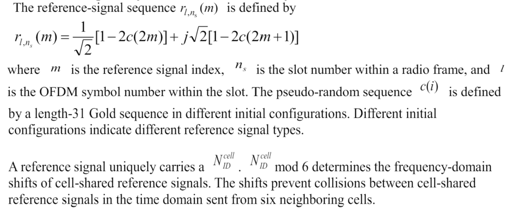
PCI Planning.
In LTE systems, eNodeBs (base stations) use specific sequences to identify and differentiate between cells.
Distinguishing Sequences:
- eNodeBs use two length-31 m-sequences, scrambled with a binary scrambling code to define the Primary Synchronization Signal (PSC).
- Cells are further distinguished using three length-62 Zadoff-Chu (ZC) sequences with root sequence indices µ = 35, 29, and 34.
Physical Cell Identifiers (PCIs):
- There are 504 unique PCIs that provide satisfactory orthogonal performance, ensuring minimal interference between cells.
- These PCIs are numbered to avoid confusion.
PCI Reuse and Interference
Insufficient PCI Reuse Distance:
- Although each cell has a unique PCI, the reuse distance (the minimum distance between cells using the same PCI) is often insufficient.
- This can lead to interference between non-correlated pilot signals from different cells.
Potential Issues:
- When a UE (User Equipment) experiences interference, it may incorrectly trace pilot signals.
- Errors in identifying the correct eNodeB can lead to unexpected handovers to different cells, potentially causing service drops or interruptions.
The main problem arises when the 504 PCIs are reused, leading to insufficient separation between cells with the same PCI. This can cause interference and errors in pilot signal tracking, resulting in service issues for the users.
What is a PCI Collision?
In LTE networks, collisions can occur if neighboring cells are assigned the same Physical Cell Identifier (PCI). Here’s a simplified explanation of this issue:
- Neighboring Cells with the Same PCI:
- When two neighboring cells are allocated the same PCI within the same frequency band (intra-frequency network), it leads to a collision.
Impact on User Equipment (UE)
- Detection and Synchronization:
- In such a scenario, the UE can detect and synchronize with only one of the cells during the initial cell search.
- Handover Problems:
- If the synchronized cell does not meet the handover requirements, the UE may fail to connect to the appropriate cell, leading to a collision.
- This can cause issues such as dropped calls or interrupted data services, as shown in Figure below.

What is PCI Confusion?
In LTE networks, confusion can arise if neighboring cells are assigned the same Physical Cell Identifier (PCI). Here’s a simplified explanation of this issue:
- Neighboring Cells with the Same PCI:
- When neighboring cells share the same PCI (e.g., ID A in Figure below), it can lead to confusion during handover processes.

Impact on Handover
- eNodeB Decision-Making:
- During a handover, the eNodeB needs to determine the target cell to which the UE should be handed over.
- If neighboring cells have the same PCI, the eNodeB cannot accurately identify which cell is the intended target.
Resulting Confusion
- Ambiguity in Target Cell:
- The eNodeB’s inability to distinguish between the cells with the same PCI leads to confusion.
- This confusion can result in failed handovers or the UE being handed over to the wrong cell, causing service disruptions.
PCI Planning in LTE Networks.
Proper Physical Cell Identifier (PCI) planning is crucial to avoid issues like confusion and collision in LTE networks. Here are the key principles and considerations for effective PCI planning:
Principles of PCI Planning
- Avoid PCI Confusion and Collision:
- Ensure that PCIs are assigned in a way that neighboring cells do not have the same PCI to avoid confusion and collision.
- Intra-Frequency Neighboring Cells:
- If a serving cell has neighboring cells on the same frequency (intra-frequency) with strong interference, these neighboring cells must not use the same PCI as the serving cell. This principle does not apply to cells on different frequencies (inter-frequency).
- Signal Strength Considerations at Cell Edges:
- At the edges of a serving cell, the pilot signals from neighboring cells can be stronger than the signal received by the UE from its serving cell, causing interference.
- Weak pilot signals from non-neighboring cells can cause interference if received at the cell edge. These nearby cells can use the same PCI as the serving cell only if the interference is below a certain threshold.
- Non-Interfering Cells:
- Cells that do not interfere with the serving cell can use the same PCI as the serving cell.
- Staggered Pilot Symbol Positions:
- The position of pilot symbols is related to the PCI code. To prevent interference and improve network performance, pilot symbols of neighboring cells should be staggered to the maximum extent.
- In the frequency domain, the position of pilot symbols is determined by:
- PCI MOD 3 for two- and four-antenna scenarios.
- PCI MOD 6 for single-antenna scenarios.
- Consistency and Expansion:
- PCI planning should facilitate easy network expansion. The PCIs of cells managed by the same eNodeB should belong to the same PCI group, while PCIs of neighboring eNodeBs should belong to different PCI groups.
Indoor Coverage PCI Planning
For indoor coverage scenarios, PCI planning has additional considerations:
- Few RRUs:
- If there are only a few Remote Radio Units (RRUs) covering an indoor area (typical in early deployment stages) and macro eNodeBs are used for coverage, PCIs can be planned similarly for both indoor and outdoor scenarios.
- Many RRUs:
- If many RRUs cover an indoor area, PCIs must be planned separately for indoor and outdoor scenarios. In this case, PCI reuse can be maximized.
Effective PCI planning is essential to ensure robust and interference-free operation in LTE networks. By adhering to these principles, network planners can minimize issues related to PCI confusion and collision, thereby improving overall network performance and reliability. This includes careful consideration of intra-frequency interference, signal strength at cell edges, and the specific needs of indoor and outdoor coverage.
PCI Planning Using the U-Net.
Huawei’s U-Net platform provides robust tools and methodologies for PCI planning in LTE networks, supporting both newly deployed and expanded eNodeBs. By grouping eNodeBs into clusters and prioritizing PCI groups, U-Net ensures efficient and interference-free operation, enhancing the overall performance and reliability of LTE networks. This approach to PCI planning facilitates scalability and future expansion, while maintaining high-quality service delivery in various network deployment scenarios.
Below PDF document explain step by step of PCI planning with pictures.