This article establishes minimum requirements for the use of thermocouples in process plants. Main keywords for this article are What is Thermocouple Design Requirement in Process Plant , Thermocouple Application Considerations , References thermocouples
References thermocouples
Reference is made in this standard to the following documents. The latest issues, amendments and supplements to these documents shall apply unless otherwise indicated.
American Petroleum Institute (API)
RP 550 Manual on Installation of Refinery Instruments and Control Systems
RP 551 Process Measurement Instrumentation
American Society of testing of Material (ASTM)
E 230-03 – Standard Specification and Temperature-Electromotor Forces (EMF) Tables for Standardized Thermocouples
The Instrumentation, Systems, and Automation Society (ISA)
ISA/ANSI MC 96.1 – Temperature Measurement Thermocouples
Definitions
For the purpose of understanding this standard, the following definitions apply:
Grounded/Ungrounded. Refers to the presence or absence of an electrical connection between the ’low’ side of the transducer element and the portion of the transducer intended to be in contact with the test structure. Method of grounding should be stated as ’internally ungrounded’ or ’by means of separate stud’.
Linearity. Characteristic of a device or system which can be described by a linear differential equation with constant coefficients.
Natural Frequency. The frequency of free (not forced) oscillations of the sensing element of a fully assembled transducer.
Noise. An unwanted component of a signal or variable.
Sensing Element. That part of the transducer which responds directly to the value of measured variable.
Shield. Surrounding earthed metallic layer to confine the electric field within the cable and to protect the cable from external electrical influence.
Thermocouple. A temperature measuring instrument that develops an electric voltage when heated because of the combined thermoelectric effect due to dissimilar composition between two electrically connected conductors (usually wires) and to temperature difference between the connection (hot junction) and the other end of the conductors (cold junction).
Thermowell. A thermowell is a pressure-tight receptacle adapted to receive a temperature sensing element and provided with external threads of other means for pressure-tight attachment to a vessel.
The design and fabrication of thermocouples and extension wires shall conform to ISA/ANSI MC 96.1. The installation of temperature instruments shall conform to API-RP 550/551.
What is Thermocouple Design Requirement in Process Plant
- All thermocouples used in plants shall be ungrounded unless they are supplied as part of package units.
- Type T thermocouples shall be used for temperature ranges -300 deg F (-195 deg C) to 200 deg F (95 deg C).
- Type K thermocouples shall be used for temperature ranges 200 deg F (95 deg C) to 2000 deg F (1090 deg C).
- Thermocouples shall be used for indication loop. Thermocouple with temperature transmitter shall also be used for control and shutdown loops if high temperature does not permit use of RTD.
- A single thermocouple signal shall not be connected to more than one device. To connect to more than one device, the signal shall first be converted to standard voltage or current signal.
- Thermocouples shall be metal sheathed, 316 stainless steel, and mineral insulated with 6mm (1/4 inch) stem diameter.
- The thermocouple signal transmission shall be shielded for minimum noise.
- The thermocouple wiring shield shall be grounded at only one point.
- For temperature electromotor force tables refer to E 230-03.
Thermowells
For Thermowell designs and mounting details. Click Here.
Thermocouple Application Considerations
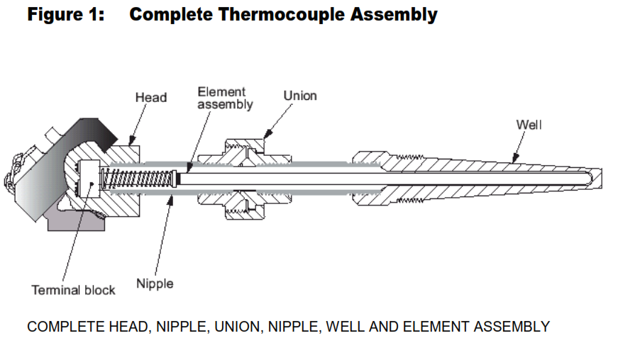
- The Thermocouple assembly shall include a 1/2 inch x 3 inch nipple, 1/2 inch union and ½ inch x 3 inch nipple to assemble the thermocouple to the aluminum head. The two nipples shall be 316SS. See Figure-1.
- The Thermocouple assembly consisting of sensor, thermowell and connection head (or direct mounted transmitter) shall carry the hazardous location certification for the site of installation.
The following is recommended for maximum accuracy: - Use extension wire connections which do not interpose different metals between the connected leads, or use terminal blocks of thermocouple material.
- Insert the thermocouple into the pipeline or vessel deep enough that true temperature is not lowered by heat flow from the tip of the thermowell or thermocouple to the outside of the
vessel or pipeline. Generally, insertion is four times the diameter of the thermowell for unjacketed pipe or vessels, and ten times for jacketed pipe. - Spring load the thermocouple in the thermowell to ensure good thermal contact. Two and one-half pounds of contact is adequate.
- Avoid locating the thermocouple in an area of high induced EMF or electrical noise. Where it is necessary to do so, additional conditioning equipment shall be used.
- Adjust temperature readings for nonlinearities in the thermocouple calibration. Recorders typically do this on the chart or scale. Program computers for corrections.
- Establish a specific calibration procedure. Thermocouples drift. The amount of drift will depend on type of thermocouple, temperature range, and environmental conditions.
- Wire insulation shall be compatible with ambient temperature. For ambient temperature up to 100 deg C, polyvinyl chloride is acceptable. Above 100 deg C non asbestos insulation is required.
