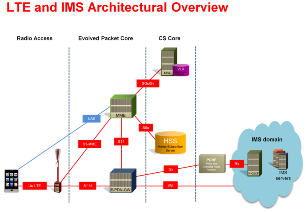
VoLTE stands for voice over LTE. VoLTE services depend on seamless integration between LTE (and existing 3G/2G) networks and the IMS. The connection is established at the PDN-GW through the IP-based SGi interface. IMS also connects to PCRF for policy and charging control and retrieves subscriber data from the HSS.
Signaling between users and IMS utilizes SIP (RFC 3261) and occurs over the user plane via a default bearer, established during LTE core network registration. Importantly, IMS handles only signaling, with no user data processed directly.
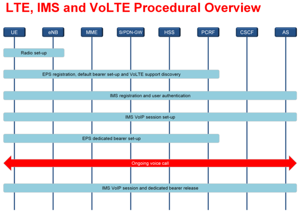
LTE, IMS and VoLTE Procedural Overview.
To access VoLTE services, several steps are required for the VoLTE client device:
- Radio Connection Setup: The UE connects to the E-UTRAN via random access and establishes RRC to support signaling messages.
- EPS Registration: The UE uses NAS protocols for EPS registration, setting up a default bearer and IP allocation, with potential security measures.
- IMS Registration: The IMS client on the UE registers for services, which may include additional authentication. The IP connection remains active even if the RRC connection deactivates.
- Call Setup: When initiating a call, the UE re-establishes the RRC connection, sets up SIP signaling, and creates bearers for media flow.
- Call Termination: SIP signaling terminates the session, and the RRC connection deactivates after the call ends.
EPS Registration Procedure.
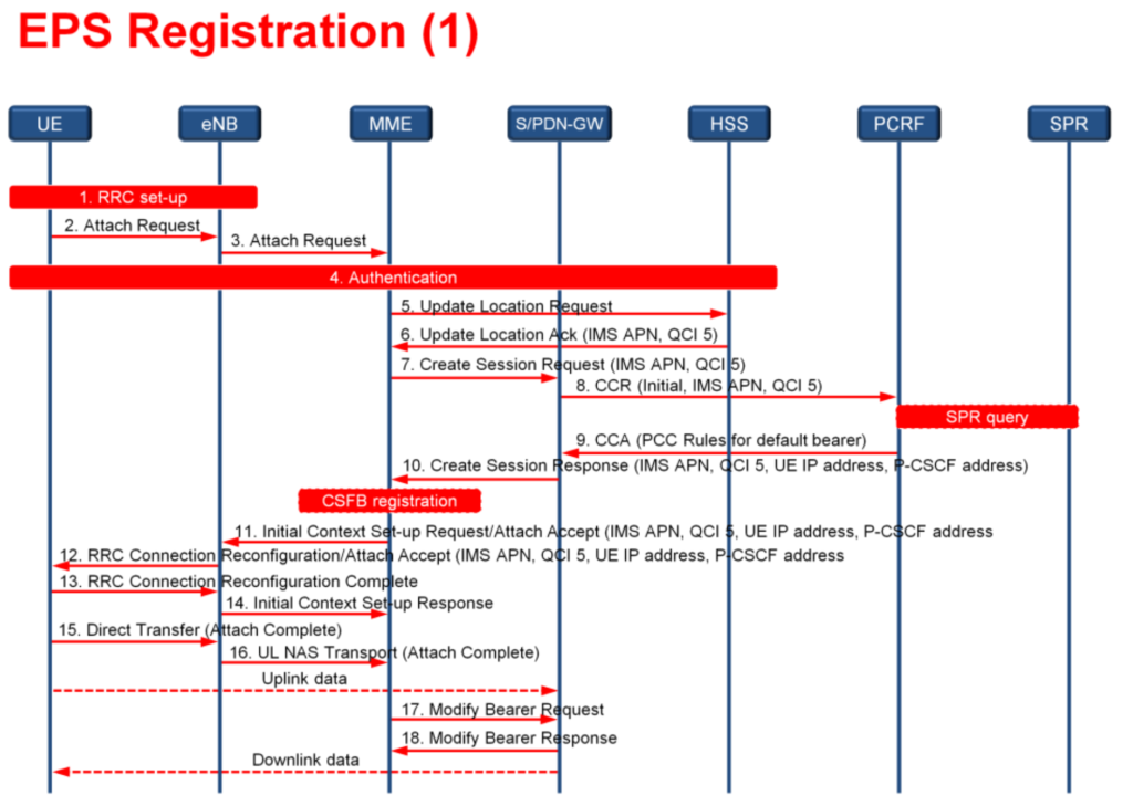
1. Random Access and Connection Setup.
The UE initiates a random access procedure to establish a signaling connection with the eNodeB and MME. This step includes creating an RRC (Radio Resource Control) signaling connection.
2. Attach Request Transmission.
The UE sends an Attach Request message to the eNodeB, including its voice preferences:
- Voice domain preference: CS or IMS-based PS.
- Usage settings: Voice-centric or data-centric configurations.
- SRVCC capability: GERAN/UTRAN support.
3. Forwarding to MME.
The eNodeB forwards the attach request to the selected MME via an S1AP control message.
4. Authentication and Location Update.
The MME initiates authentication procedures to verify the UE’s credentials. The MME sends an Update Location Request to the HSS to update the subscriber’s IMSI location.
Subscription Context Retrieval from HSS:
The HSS provides an Update Location Acknowledgment to the MME, including critical subscription details:
- PDN Type: IPv4v6.
- APN:
imsfor SIP signaling. - QCI: 5 for IMS signaling traffic.
- ARP: 9 (priority level).
- APN-AMBR: Defined UL and DL bandwidth limits.
- VPLMN Access: Allowed for roaming scenarios.
Bearer Configuration:
A default bearer is established for SIP signaling between the UE and the IMS. This bearer ensures connectivity while aligning with QoS parameters provided by the HSS.
Subscription and QoS Validation:
The MME validates subscription data and QoS values, ensuring compliance with any roaming restrictions. Preferred APN (ims) is selected for PS voice services. Based on the APN, the MME selects the PDN-GW, while the SGW selection depends on the UE’s location. The MME initiates default bearer creation by sending a Create Session Request to the SGW.
9. Dynamic PCC Rules:
- The PDN-GW retrieves default PCC rules for the UE via the IP-CAN session establishment procedure.
- Communication with the PCRF involves exchanging key parameters, such as:
- Subscriber identity, IP address (v4/v6).
- IP-CAN type, access network type.
- The PCRF may query the SPR if additional data is needed and sends bearer QoS details, including QCI, ARP, and bit rate limits, to the PDN-GW.
10. PDN-GW Context Creation:
A new PDN-GW EPS bearer context is created for routing (PDN-GW–SGW). The PDN-GW sends a Create Session Response to the SGW, providing:
- Default bearer ID, UE IP address, and P-CSCF address (via PCO).
11. Attach Acceptance:
MME verifies bearer modifications and calculates the aggregated maximum bit rate. If combined attach (PS/CS) is required, IMSI is sent to an MSC via the SGs interface. An Attach Accept message, including the TAI list, is sent to the UE via the eNB within the Initial Context Setup Request.
12-13. Bearer and Configuration Setup:
eNB sends an RRC Reconfiguration message to the UE, detailing EPS bearer, QoS, UE IP, and P-CSCF address. The UE confirms via RRC Reconfiguration Complete.
14-15-16. Context and NAS Completion:
eNB confirms with an Initial Context Setup response to the MME. The UE sends a Direct Transfer message to the eNB, including the Attach Complete (EPS Bearer ID, NAS SQN). Attach Complete is relayed to the MME, enabling UL packet tunneling through the SGW and PDN-GW.
17-18. Bearer Modification and Packet Exchange:
MME sends a Bearer Modify message to the SGW, followed by a Modify Bearer Response. With UL/DL packet exchange enabled, the UE can now exchange SIP signaling with the IMS for VoLTE services.
Default Bearer Set-up and Parameters.
The diagram below shows the relationship between the PDN connection and the default bearer in LTE. A PDN connection, identified primarily by an IP address, spans multiple interfaces, including the air interface, S1, and S5. The default bearer, established during UE registration, is a managed part of the PDN connection, with specific parameters set to control how packets are handled across E-UTRAN and EPS nodes. These parameters ensure efficient and consistent communication for the bearer during network operations.

| Parameter | Purpose | Example Values |
| Context Identifier. | Index of the PDN subscription context. | 5 |
| PDN Type. | Indicates the subscribed PDN type (IPv4. IPv6, IPv4v6) that is, whether IPv4, IPv6 or both addresses are allocated to the UE. | 2 (IPv4v6) |
| Service-Selection (Access point name). | A label according to DNS naming conventions describing the access point to the PDN that is APN network identifier. | IMS |
| EPS subscribed QoS profile. | Th bearer-level QoS parameter values for that APN’s default bearer, including QCI ad ARP (priority and pre-emption) | 5 (QCI5) 9 (priority-level) 1 (preemption_capability_disable) 0 (pre-emption_vulnerability_enabled) |
| Subscribed APN-AMBR. | The maximum aggregated UL and DL MBR to be shared across all non-GBR bearers that ate established for this APN. Maximum bandwidth is in bits per second and it contains all the overhead coming from the IP layer and the layers above, for example IP, UDP, RTP And RTP payload. | 500 000 (max-requested bandwidth-UL 1000 000 (max-requested bandwidth-DL). |
| VPLMN address allowed. | Specifies whether for this APN the UE is allowed to use the PDN GW in the visited operator network. For VoLTE roaming this must be enabled because the PDN-GW is always selected from the VPLMN. | 1 (allowed). |
IMS Registration.
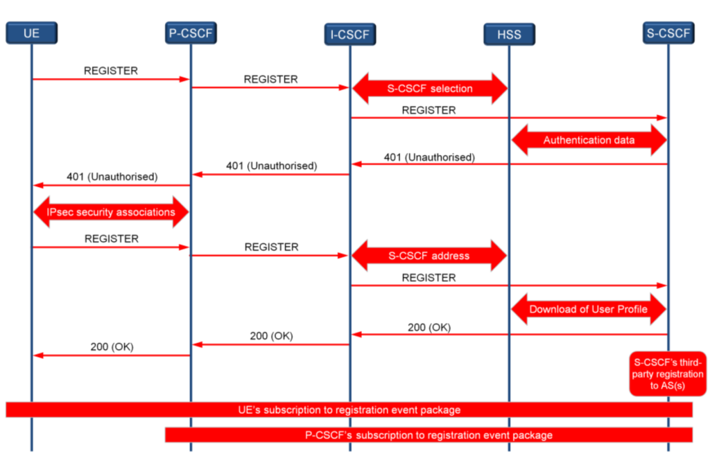
Once the UE establishes connectivity to the IMS via the default bearer, it can begin communication, starting with the registration process. The SIP client in the UE registers its IP address with the IMS to identify its current location (IP-based, not physical). This process also establishes a route between the UE and the serving CSCF. Key steps include:
- REGISTER Message: UE sends a SIP REGISTER message to the P-CSCF.
- Proxy Forwarding: P-CSCF forwards it to the I-CSCF, which selects the S-CSCF with HSS assistance.
- Authentication: S-CSCF performs authentication and sends a 401 response, enabling security setup.
- IPsec Security: Security associations are established between UE and IMS.
- Routing Information: SIP headers facilitate routing.
- Profile Download: S-CSCF retrieves user profile from the HSS.
- Service Registration: UE registers supported IMS services.
- App Server Registration: Based on subscription, UE may be registered with application servers.
- Identity Awareness: Both UE and S-CSCF update public user identities and registration statuses.
- Charging Info: P-CSCF learns charging function addresses.
This process ensures secure and functional communication between the UE and IMS.
Identities for IMS
IMS service subscriptions are based on user identities. Specifically, a user will have one private identity and one or more public identities which are mapped to the private identity. The private identity is referred to as the IMPI (IM Private Identity) and the public identity, or identities, are known as the IM Public Identity (IMPU). This is identical in concept to the IMSI (private) and MSISDN (public), where a user may have several MSISDNs mapped to one IMSI.

The IMS profile of a user stored on the HSS is made up of one or more service profiles. There is only one service profile per public identity, although one profile may be mapped to more than one identity. Service profiles contain triggers (known as filter criteria) which are used to launch IMS services. These filters are relatively static; in future releases dynamic filters will be set by the service logic on an AS.
The public and private user identities are stored in the IM Subscriber Identity Module (ISIM) and the HSS. Service profiles are downloaded from the HSS to the S-CSCF at, for example, registration.
A public user identity can be a SIP URL, for example: sip:user@domain, or a ‘tel’ URL, for example: tel:+123-123-1234567.
Where a subscriber has multiple public addresses, the registration of one of those addresses can be used to implicitly register other addresses. For this to work the addresses must be grouped together in a registration set.
The private user identity used for IMS services is in the form of an NAI (Network Access Identifier), for example: fred@domain.com or fred@ims.operator.com. It is possible for a representation of the IMSI to be coded into the NAI.
Relationship of IMS Identities.

In this example of identity relationships, the user has two different service profiles identified with differing public user identities. Each of the service profiles may result in different handling of the communication services due to the way in which the services are registered with the relevant S-CSCF and AS. Regardless of how many public user services and profiles there are they will be mapped back to a single private identity which is used in the initial registration of the user.
Where the user has multiple devices it is possible to have an public identity that is linked or registered to several private identities.
IMS Service Provisioning.
LTE and UMTS PS are simply IP-based packet networks that efficiently route packets from and to the UE. Moving packets can not be classed as a ‘service’; the IMS, however, can be considered to provide a function for creating and managing actual services, such as voice, video, IM, etc. The name given to this process within IMS is ‘service provisioning’.

The data concerning the IMS subscriber and services resides in the HSS. This information will be accessed by the S-CSCF (SIP server) when the IMS user registers for the service. The S-CSCF can then determine how to manage the service based on this subscription information. This may require that the request for session (coming from the IMS subscriber) will be sent to the AS for additional parsing. An example of an AS might be the Telephony AS (or TAS), which understands how to execute services related specifically to telephone services, for example call forwarding, conferencing, etc.
Service Triggering and Initial Filter Criteria.
In this example of service provisioning the S-CSCF receives a request for a session to
be established (e.g. INVITE).
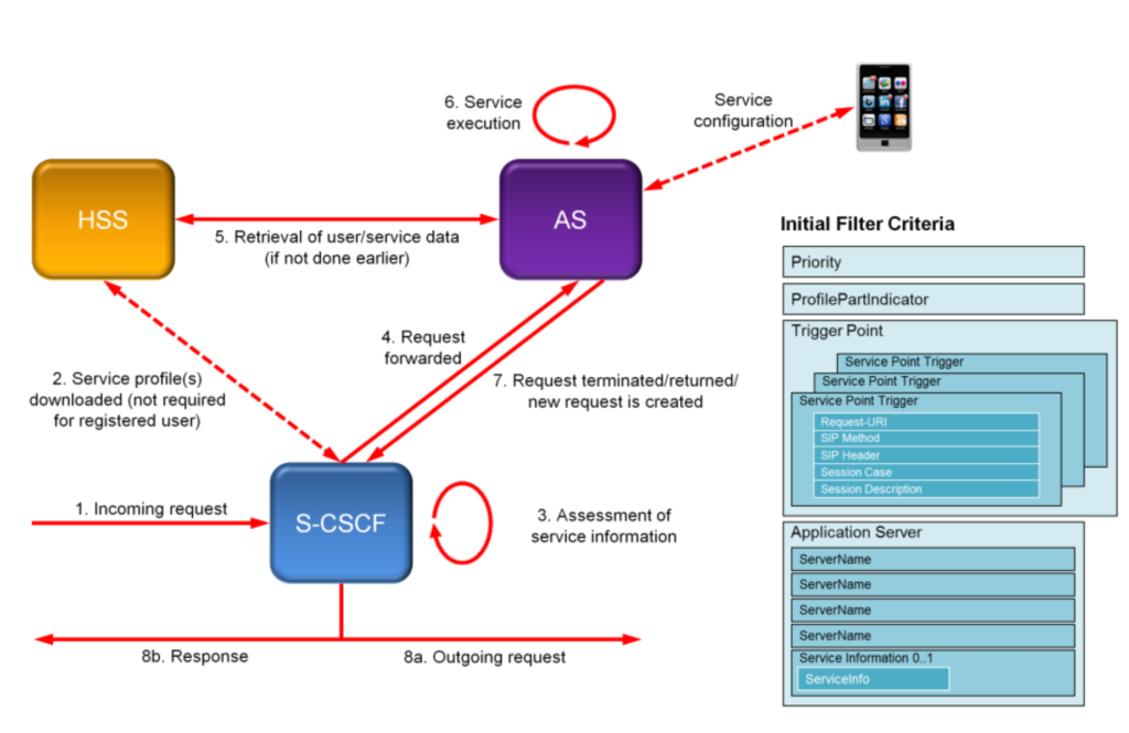
In order that the S-CSCF understands how to proceed, the request will be evaluated by the server, comparing the session request with subscriber-related information, which may be held at the S-CSCF or downloaded from the HSS.
At this point the S-CSCF will also consider the filter criteria (see the following diagram). The filter criteria help the S-CSCF determine the next logical step in executing the service. The filter criteria can be any element or information present or not present in the incoming request; for example, the SIP message type or session description information can be used. The filter criteria can therefore be used to determine which AS the request should be forwarded to in order to execute the service.
The AS that the request is forwarded to, may also interrogate the HSS for additional subscriber information.
The IMS may have several ASs, each one specialising on a particular service, i.e. voice, SMS, IM, video streaming, therefore the filter criteria and the logic used to process it must setup correctly to ensure the service request is routed to the correct AS.
VoIP Session Set-up.
In this voice call session establishment sequence the originating user presents the SIP INVITE to the originating network’s IMS. In this case the P-CSCF will determine the route to the S-CSCF and forward the message. The S-CSCF will route the message to an AS determined by the filter criteria; the AS may modify the INVITE according to the requirements for the session. This may include modifying the session description and providing routing information to the intended network.

The S-CSCF will route the INVITE message toward the destination user via the I-CSCF. The I-CSCF will determine which S-CSCF should handle the session request. it may do this by interrogating the HSS. The IMS components will then begin to forward the INVITE toward the user within that network, applying filter criteria if necessary.
This initial routing and forwarding of the session request is important, not just to deliver the message to the destination party, but also to establish the actual route the subsequent message will follow. Each of the SIP servers (CSCFs) will add or remove routing labels from the SIP header information to ensure accurate routing.
The destination system will indicate that an attempt to contact the user is being made (100 Trying). In this example, when the destination party responds to the initial INVITE, it sends a progress message 183, which starts the media negotiation process in which both ends determine which media codecs should be used for the session. The subsequent messages, PRACK from the originating party and 200 OK from the destination, also form part of this media negotiation.
The UPDATE and 200 OK messages indicate that the required resources have been reserved for the communication and the ringing (alerting) process can begin. When the user answers the call a final 200 OK message is sent, and acknowledges with ACK.
At this point both the originating and destination parties will know the source and destination IP addresses and have resources (dedicated EPS bearers) established, so the flow of media can begin.
Dedicated Bearer Establishment
When a SIP session is being set up, it will generally require a bearer to be established from each party in the call to the PDN-GW. During session signalling the P-CSCF will inform the PCRF that a bearer is required along with the QoS parameters relevant for the session. The PCRF will then initiate the dedicated bearer toward the user.
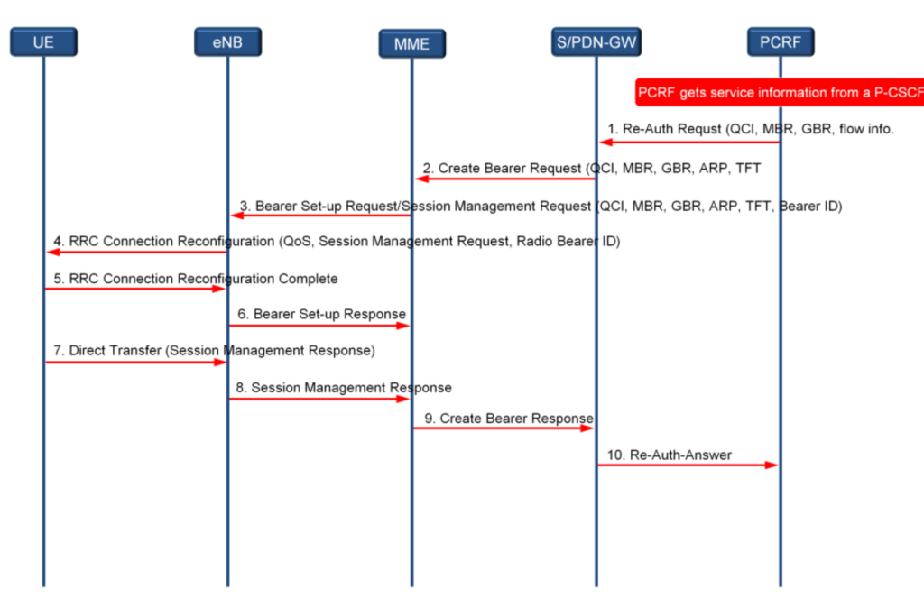
Note that the bearer being created is the path that will be taken by the media (voice) once the session is been fully set up. All the SIP-based signalling is using the default bearer established by the EPC during the UEs registration to the EPC.
VoLTE Session Release.

When either user indicates that the session is to be released, either by hitting the endcall button or closing an application, the SIP BYE message will be sent to the S-CSCF. The BYE message will pass through all the IMS signalling nodes allowing them to terminate any billing -elated activities (STR/STA to the PCRF) and to indicate to the transport plane that dedicated bearer should be terminated (RAR/RAA to the PDNGW).