In the world of control engineering, maintaining precise control over industrial processes is paramount to achieving optimal performance, efficiency, and safety. Enter the PID (Proportional-Integral-Derivative) controller, a sophisticated and widely used control mechanism that has revolutionized automation and process control.
In this comprehensive guide, we tried to explain the fundamentals of the PID controller, exploring its working principles, key components, and real-world applications. Whether you are a seasoned control engineer seeking to refresh your knowledge or a curious learner eager to understand this crucial aspect of control systems, join us on this journey to unravel the power and versatility of the PID controller.
PID Controller in Control System
A PID controller, short for Proportional-Integral-Derivative controller, is a fundamental component of a control system used to regulate a process or system. It is a type of feedback control that continuously calculates and adjusts the control output based on the difference between the desired setpoint and the actual process variable (PV).
The PID controller uses three components to achieve control:
- Proportional (P) Control: The proportional term calculates the control output based on the present error, which is the difference between the setpoint and the PV. The controller output is directly proportional to the error, and its purpose is to reduce the error quickly.
- Integral (I) Control: The integral term calculates the control output based on the accumulated sum of past errors over time. It helps in eliminating any steady-state error that might persist even after the proportional control has brought the error close to zero.
- Derivative (D) Control: The derivative term calculates the control output based on the rate of change of the error. It anticipates future errors by considering how fast the error is changing and helps in damping any oscillations or overshooting.
By combining these three components, the PID controller efficiently adjusts the control output to reach and maintain the desired setpoint while minimizing deviations and maintaining stability.
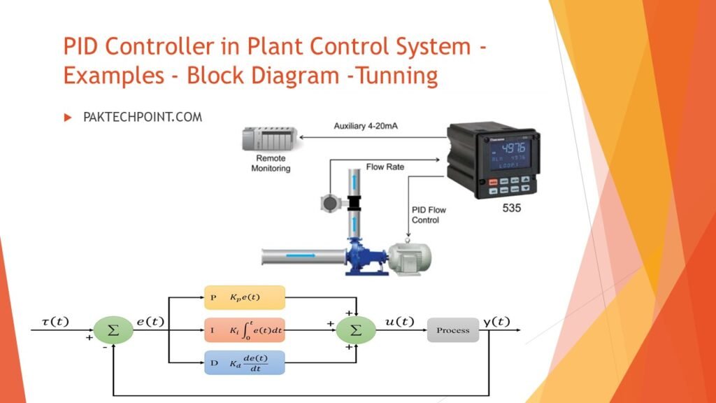
The PID controller is widely used in various industrial and process control applications, such as temperature control, pressure control, flow control, motor speed control, and more. Its versatility, ease of implementation, and effectiveness in a wide range of systems make it a fundamental and essential tool in control engineering.
PID Control Basics
This concept is based on the Feedback loop control. As shown in the following figure
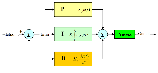
PID Controller minimizes the error by calculating difference between process variable and desired value (set point) by adjusting the control valve in industrial process. This acronym works stands for Proportional Integral Derivative control.
Proportional control removes the fluctuation by adjusting the set point. The offset remains behind the proportional control, adjusted by the Integral control.
The third one is Derivative control which is very noise sensitive and never be used in system where lots of noise. It is used for stability of system and its stability effect is greater than destabilizing effect of I-Control.
Mathematical form of PID Controller
The mathematical form of a PID (Proportional-Integral-Derivative) controller is represented by the following equation:
u(t) = Kp * e(t) + Ki * ∫[e(τ) dτ] + Kd * de(t)/dt
Where:
u(t) is the control output at time t.
e(t) is the error, calculated as the difference between the desired setpoint and the actual process variable (e(t) = setpoint – process variable).
Kp, Ki, and Kd are the tuning parameters or gains for the proportional, integral, and derivative terms, respectively.
∫[e(τ) dτ] represents the integral of the error over time, which is the accumulated sum of the error values.
de(t)/dt is the derivative of the error with respect to time, indicating how fast the error is changing.
The PID controller continuously calculates the control output (u(t)) based on the weighted combination of the error and its integral and derivative components. The proportional term (Kp * e(t)) reacts to the present error, the integral term (Ki * ∫[e(τ) dτ]) accounts for past errors, and the derivative term (Kd * de(t)/dt) anticipates future errors to provide a well-balanced and responsive control action.
The tuning parameters (Kp, Ki, Kd) are critical to achieve optimal control performance, and finding the right values often involves experimentation and system-specific considerations. Properly tuned PID controllers can effectively regulate processes, minimizing overshooting, settling time, and steady-state errors.
This controller is particular useful only for process industry where accuracy matters.
Read Also:
- Fieldbus Cable and Segment Check Procedure.
- Fieldbus Applications.
- Foundation Fieldbus Overview.
- Fieldbus Technology.
- Introduction to Fieldbus.
History of PID Controller
The history of the PID controller dates back to the late 19th century when pioneering engineers and scientists laid the groundwork for modern control systems. The concept of feedback control emerged with the work of James Clerk Maxwell in the 1860s, who proposed using feedback to control a governor regulating steam engines.
The foundation for the PID controller was established by Nicolas Minorsky, a Russian engineer, who in 1922 developed the first automatic steering system for ships. Minorsky’s system utilized a form of proportional control to maintain a ship’s desired course by measuring the error between the actual and desired heading.
In the 1930s, Elmer Sperry refined and patented the gyroscopic autopilot system, which further advanced the use of proportional control in maintaining stable flight paths for aircraft.
The PID controller, as we know it today, was formulated in the 1940s. First, the proportional control element was introduced, followed by the integration of the integral and derivative control elements. The works of Harold Stephen Black, a prolific American engineer, were instrumental in shaping the theoretical foundations of the PID controller.
Since then, the PID controller has become a cornerstone in control engineering, finding applications in diverse industries such as manufacturing, robotics, process automation, and even consumer electronics. Continuous research and development have led to various PID controller variations and advanced control algorithms, further enhancing its effectiveness and adaptability in modern control systems.
PID Temperature Controller
A PID temperature controller is a vital component of temperature control systems used in various industries. Its main function is to maintain a stable and precise temperature by continuously comparing the actual temperature to the desired setpoint. Based on this comparison, the controller adjusts the output to a control element, such as a heating or cooling device, to ensure the temperature stays within the desired range.
By employing the proportional, integral, and derivative control elements, PID temperature controllers offer excellent accuracy and responsiveness to dynamic changes, resulting in efficient and reliable temperature regulation. This automation eliminates the need for constant manual adjustments, making it an essential tool for maintaining consistent and controlled environments in processes like manufacturing, research, and industrial operations.
Tips for Designing a PID Controller
Designing a PID controller requires careful consideration and tuning to ensure optimal performance. Here are some general tips to keep in mind when designing a PID controller:
- Understand the System: Have a thorough understanding of the process or system that you want to control. Identify its dynamics, response time, and any non-linearities or disturbances that may affect it.
- Start with P-Only Controller: Begin by setting the derivative and integral gains to zero, creating a proportional-only (P-only) controller. Adjust the proportional gain (Kp) to get a response that stabilizes the system but may lead to some oscillations around the setpoint.
- Add Integral Action: Introduce the integral term (Ki) to eliminate steady-state errors caused by external disturbances or system biases. Adjust Ki to reduce steady-state errors without causing excessive overshoot or instability.
- Incorporate Derivative Action: Introduce the derivative term (Kd) to improve the controller’s response to rapid changes and reduce overshooting. Be cautious with derivative action, as it can amplify noise and lead to instability if not carefully tuned.
- Tune Parameters Step-by-Step: Tune the PID gains step-by-step, starting with Kp, then Ki, and finally Kd. Fine-tune each parameter iteratively until the desired response is achieved.
- Use Ziegler-Nichols Method: If you don’t have prior knowledge of the system, the Ziegler-Nichols method can help you tune the PID gains experimentally. Start by setting Ki and Kd to zero, and increase Kp until you observe sustained oscillations. Then, use specific formulas to determine the appropriate gains.
- Consider Saturation and Anti-Windup: Account for saturation limits on the actuator output and implement anti-windup mechanisms to prevent integral windup when the actuator reaches its limits.
- Test in Real Environment: Test the PID controller in the real system environment to validate its performance and make any necessary adjustments.
- Fine-Tune and Monitor: Continuously monitor the system’s behavior and fine-tune the PID gains as needed to adapt to changing conditions or requirements.
- Simulation and Modeling: Utilize simulation and modeling tools to understand the system’s behavior and predict the effect of PID tuning before implementing it in the actual control system.
Remember that the ideal PID tuning can vary depending on the specific system, and achieving the perfect balance between stability, speed of response, and accuracy may require some trial and error.
PID Controller Types
PID controllers are classified into three main types: ON/OFF, Proportional, and Standard Type controllers, each serving different control system needs.
- ON/OFF Control: This simple type of controller turns the output ON when the temperature crosses a set point and turns it OFF when it reaches another set point. It is often used in basic temperature control systems.
- Proportional Control: This controller reduces the power supplied to the heater once the temperature reaches the set point to avoid excessive cycling. It achieves temperature control by adjusting the ratio of ON and OFF time periods.
- Standard Type PID Controller: This advanced PID controller combines proportional, integral, and derivative control to automatically compensate for system changes. These controllers offer precise and stable temperature control.
Real-Time PID controllers are widely used in industrial applications, and they can be implemented as separate PID controllers or integrated into Programmable Logic Controllers (PLCs). PLCs with PID blocks offer more advanced control options and are commonly used in industrial control applications for pressure, temperature, level, and flow control.
PID Controller Tunning Methods
Let’s Explain into each of the PID controller tuning methods for a better understanding:
- Trial and Error Method: This method involves manually adjusting the controller gains while the system is in operation. First, the integral (Ki) and derivative (Kd) terms are set to zero, and the proportional gain (Kp) is increased gradually until the system exhibits oscillatory behavior. Once the oscillations are observed, the integral term (Ki) is adjusted to eliminate the oscillations, and the derivative term (Kd) is fine-tuned to achieve a faster response without introducing excessive oscillations.
- Process Reaction Curve Technique: In this open-loop tuning method, a step input is applied to the system, and the response curve is recorded. From the response curve, parameters such as the slope, dead time, and rise time are calculated. These values are then used to determine the PID gains, which are substituted into the PID controller equations to achieve the desired control performance.
- Zeigler-Nichols Method: This closed-loop tuning method offers two variations: the continuous cycling method and the damped oscillation method. The continuous cycling method involves increasing the proportional gain (Kp) until the system exhibits constant oscillations. The ultimate gain (Ku) and ultimate period (Pc) are obtained from the oscillation characteristics. These values are then used to determine the PID gains from a Zeigler-Nichols table, which differs based on the type of controller (P, PI, or PID) being used.
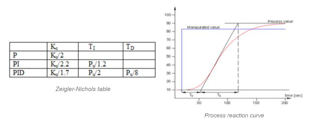
The Zeigler-Nichols method with its two variations can provide faster tuning results compared to the trial and error method. However, it may lead to initial instability during the tuning process, and the user must be cautious during implementation. The process reaction curve technique is more accurate but requires additional time and effort for data collection and analysis.
The choice of PID tuning method depends on factors such as the complexity of the control system, desired control performance, and available resources for data collection and analysis. Properly tuned PID controllers ensure stable and precise control, leading to efficient and optimized industrial processes.
PID Controller Applications
PID controllers are widely used in various applications across different industries due to their effectiveness in regulating and maintaining process variables at desired setpoints. Some common applications of PID controllers include:
- Temperature Control: PID controllers are extensively used in temperature control applications, such as in ovens, furnaces, refrigeration systems, and HVAC systems. They help maintain precise and stable temperature levels for optimal process performance and energy efficiency.
- Process Control: In industrial processes, PID controllers are employed to regulate variables like pressure, level, flow rate, and composition. They ensure that these variables are controlled within specified limits, leading to consistent and reliable process operations.
- Motor Speed Control: PID controllers are utilized in motor speed control applications to achieve accurate and smooth speed regulation. This is crucial in various industries, including robotics, automation, and manufacturing.
- pH Control: In chemical and water treatment processes, PID controllers are used to control the pH levels by adjusting the amount of chemicals added to the system. This helps maintain the desired pH range for optimal performance.
- Liquid Level Control: PID controllers are employed in liquid level control systems, such as in tanks and reservoirs, to maintain a constant level and prevent overflow or depletion.
- Pressure Control: PID controllers are used to control pressure levels in various systems, including pneumatic systems, hydraulic systems, and industrial equipment.
- Flow Control: PID controllers regulate the flow rate of liquids or gases in applications like pumps, valves, and pipelines, ensuring precise flow control and preventing wastage.
- Position Control: In robotics and motion control systems, PID controllers are utilized to control the position of mechanical components, providing accurate and smooth motion.
- Biomedical Applications: PID controllers are used in medical devices and equipment, such as infusion pumps, incubators, and anesthesia machines, to maintain critical parameters at optimal levels.
- Water Heater Control: PID controllers are applied in water heaters to maintain water temperature, ensuring consistent hot water supply without excessive energy consumption.
PID controllers are versatile and adaptive, making them suitable for a wide range of applications where precise and stable control is essential for efficient and safe operations.
PID Controller Interfacing
The interfacing of a PID controller involves connecting the controller to the process or system it is intended to control. This interface allows the controller to measure the process variable, calculate the error (difference between the setpoint and the process variable), and generate the control output to regulate the system. The PID controller interface typically includes the following steps:
- Sensor Connection: The first step is to connect the sensor or transducer that measures the process variable (PV) to the PID controller. The sensor could be a temperature sensor, pressure sensor, level sensor, flow sensor, etc., depending on the application. The PID controller reads the sensor’s output to determine the current process variable value.
- Setpoint Input: The operator or control system sets the desired value or setpoint (SP) for the process variable. The setpoint represents the target value that the PID controller will try to achieve and maintain.
- Error Calculation: The PID controller continuously compares the setpoint with the actual process variable value to calculate the error (e). The error is the difference between the setpoint and the current process variable value and is the main input to the PID controller.
- PID Algorithm: The PID controller uses the PID algorithm to compute the control output based on the error and the controller’s tuning parameters (proportional gain, integral gain, derivative gain). The PID algorithm is described as follows: Control Output (MV) = Kp * e + Ki * ∫e dt + Kd * de/dt Where:
MV = Control Output (manipulated variable)
Kp = Proportional Gain
Ki = Integral Gain
Kd = Derivative Gain
e = Error (SP – PV)
∫e dt = Integral of the error with respect to time
de/dt = Derivative of the error with respect to time - Actuator or Control Element: The control output generated by the PID controller is used to drive the actuator or control element. The actuator could be a valve, motor, heater, or any device that can adjust the process variable.
- Feedback Loop: In many PID control systems, a feedback loop is established to measure the actual effect of the control output on the process variable. The feedback loop allows the PID controller to continuously adjust the control output based on the real-time changes in the process variable.
- Tuning: The PID controller’s tuning parameters (Kp, Ki, Kd) may need to be adjusted or tuned to optimize the controller’s performance for a specific application. Tuning involves finding the right balance between stability and responsiveness to achieve the desired control behavior.
- User Interface: Many modern PID controllers come with a user interface, such as a display screen or software interface, that allows the operator to monitor the process variable, set the desired setpoint, and adjust tuning parameters.
Overall, the interfacing of a PID controller is a crucial step in implementing effective control of a process or system, ensuring that the system operates at desired setpoints and maintains stability and efficiency.
Advantages & Disadvantages
Table summarizing the advantages and disadvantages of PID controllers:
| Advantages of PID Controllers | Disadvantages of PID Controllers |
|---|---|
| Versatility: Can be used in various industries and applications. | Performance Depends on Tuning: Proper tuning is crucial for optimal performance. |
| Stability: Provide stable and smooth control of processes. | Limited for Complex Systems: Not suitable for highly complex systems. |
| Simple Structure: Easy to implement and suitable for various tasks. | Integrator Windup: Can experience integrator windup issues. |
| Fast Response: Quick to respond to changes in the process variable. | Not Optimal for Some Processes: May not be the best choice for certain applications. |
| Wide Range of Tuning Options: Parameters can be adjusted for different dynamics. | Manual Tuning Complexity: Tuning can be time-consuming and challenging. |
| Real-time Adjustment: Continuously calculate control output based on real-time error. | Robustness Issues: May not handle sudden disturbances well. |
| Effective for Linear and Non-linear Systems. | Not Suitable for Open-loop Systems: Require feedback information. |
Despite the disadvantages, P-I-D controllers remain widely used due to their simplicity, versatility, and effectiveness in many control applications.
FAQs about PID Controller in Control System
What is a PID controller, and how does it work in a control system?
How do I tune a PID controller for my specific process or application?
Can a PID controller handle non-linear systems and complex processes effectively?
What are the common challenges faced when implementing a PID controller, and how can they be mitigated?
Are there any alternatives to PID controllers for specific control scenarios, and when should they be considered?
For More Calculation of PID Controller Please Visit.