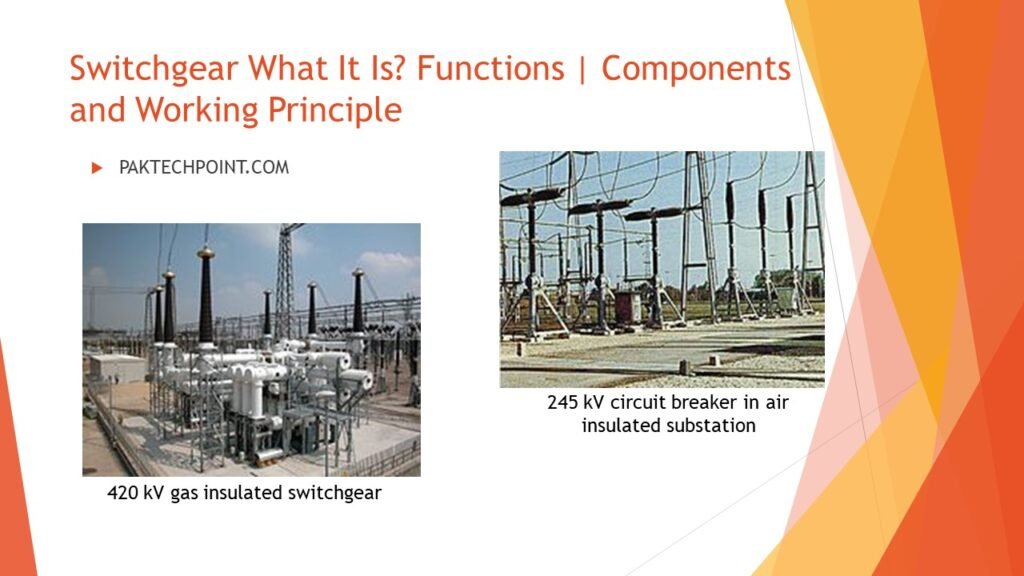
Unveiling the Power of Switchgear: Safeguarding Electrical Distribution
Switchgear, the backbone of power distribution, plays a crucial role in substations, ensuring seamless control and protection of electrical currents. In this article, we’ll explore the working principle and key components of switch gear systems, such as circuit breakers and relays, that safeguard critical equipment.
Discover the various types of switchgear used in substations, from medium to high voltage, and understand their functions in managing electrical loads and facilitating routine maintenance. We’ll also shed light on how switch gear works during outages, restoring power with swift precision.
Furthermore, explaining into the world of big switchgear manufacturers, driving innovation and shaping the future of reliable power distribution. Whether you’re an electrical engineer or simply curious about this vital technology, join us on this enlightening journey through the world of switch gear.
What is switchgear?
It is basically like panel board to handle very large voltage and current in industrial facility like waste treatment industry, power generation industry and process industry. It is made by different components like voltage and current transformer, relays, circuit breakers and metering device etc.. by logical manners.
This system is like system used in our home as circuit breaker to ON or OFF in case of short circuit. But this system is complicated because it involves high voltage and current in electrical power, it needs regulating arrangement measuring display and control.
How switchgear works?
The switchgear maintains the normal load operation and identifies the faulty operation in the network. In this when fault occurs in current transformer and voltage transformer and overload condition then it actuates the protection relay. Circuit breaker senses the operation of protection relay and take decision by turning ON or OFF to the circuit. This is basic protection system of protection system.
Working Principle
The working principle of switchgear revolves around the concept of controlling and protecting electrical power systems. Switchgear acts as a combination of electrical disconnect switches, fuses, circuit breakers, and protective relays, all working in harmony to manage the flow of electrical current and safeguard the equipment from potential faults.
When electrical current flows through the switchgear, it passes through different components that can either open or close the circuit based on specific conditions. For instance, during normal operating conditions, the switch gear allows the current to flow uninterrupted, ensuring the smooth distribution of electricity. However, in the event of a fault, such as an overload or short circuit, the protective relays sense the abnormal conditions and trigger the circuit breakers to open, instantly cutting off the current and isolating the faulty section.
The main objective of switchgear is to maintain electrical continuity while offering robust protection against potential hazards. Its ability to swiftly detect and respond to faults ensures the safety of electrical equipment and personnel, preventing damage and minimizing downtime. The working principle of switch gear is a vital aspect of power distribution systems, enabling reliable and efficient operation across various industries and substations.
Medium Voltage Switchgear
Medium voltage switchgear is a crucial component in electrical power distribution systems, designed to operate within the voltage range of 1 kV to 36 kV. It plays a vital role in controlling, protecting, and isolating electrical equipment and circuits in medium-voltage networks, ensuring safe and reliable power distribution.
This type of switchgear typically consists of various components, including circuit breakers, disconnect switches, fuses, and protective relays. Each component serves a specific function to safeguard the system from faults, overloads, and short circuits. Medium-voltage switch gear is commonly used in substations, industrial facilities, commercial buildings, and utility power distribution systems.
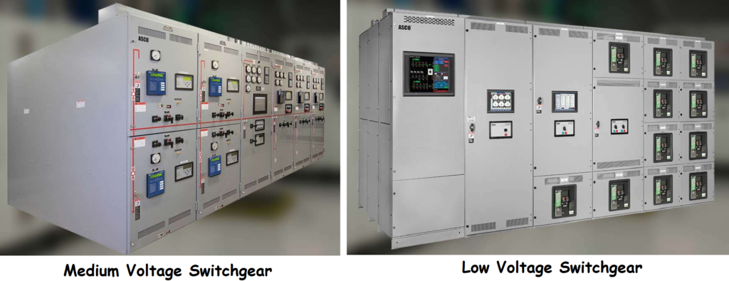
Low Voltage Switchgear
Low-voltage switchgear is a vital component in electrical power distribution systems, designed to operate within the voltage range of 1 kV or below. It serves as the control and protection hub for electrical equipment and circuits in low-voltage networks, ensuring safe and efficient power distribution.
This type of switch gear typically includes circuit breakers, contactors, relays, and other protective devices. These components work together to detect abnormal conditions, such as overloads and short circuits, and swiftly isolate the affected section to prevent further damage.
Low-voltage switchgear finds widespread applications in residential, commercial, and industrial settings. In residential buildings, it ensures the safe distribution of electricity to various outlets and appliances, while in commercial and industrial facilities, it safeguards critical equipment and machinery.
Read Also:
- Fundamentals of Automation, Process Control ? Explain with Examples of control system?
- Fieldbus Fundamentals and Difference between fieldbus and HART
- What is Surge in Compressor
Switchgear Components
Switchgear is a crucial electrical apparatus used in power systems to control, protect, and isolate electrical equipment and circuits. It comprises several essential components that work together to ensure the safe and reliable distribution of electrical power. Some of the key components of switch gear include:
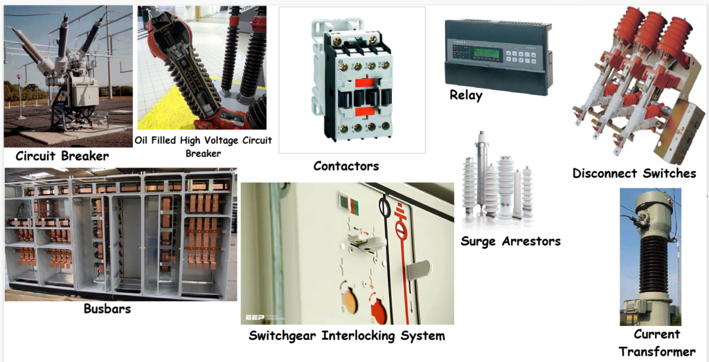
- Circuit Breakers: Circuit breakers are automatic switches designed to interrupt electrical currents in the event of abnormal conditions, such as overloads, short circuits, or faults. They play a critical role in isolating faulty sections and protecting electrical equipment from damage.
- Contactors: Contactors are electromagnetic switches used to control the flow of electrical power to motors, transformers, and other electrical loads. They provide a reliable means to turn equipment on and off remotely.
- Relays: Relays are electromechanical devices that detect abnormal conditions and trigger appropriate actions. They act as sensors, detecting variations in voltage, current, or other parameters and initiating circuit breaker operations for fault clearing.
- Busbars: Busbars are conductive bars or strips that serve as a common connection point for multiple circuits within the switch gear. They efficiently distribute electrical power from the incoming supply to various outgoing feeders.
- Disconnect Switches: Disconnect switches, also known as isolators, are manual switches used to physically isolate circuits or equipment from the power supply. They allow for safe maintenance and repairs without affecting the rest of the system.
- Surge Arresters: Surge arresters protect sensitive electrical equipment from voltage surges caused by lightning or switching operations. They divert excess voltage to the ground, safeguarding devices from damage.
- Control Panels: Control panels house various switches, indicators, and control devices used to operate and monitor the switchgear system. They provide a user interface for operators to manage the equipment effectively.
- Current Transformers (CTs) and Voltage Transformers (VTs): CTs and VTs are instrument transformers used to measure current and voltage levels in the system. They provide reduced secondary outputs proportional to the primary values for monitoring and protection purposes.
- Protective Relays: Protective relays are sophisticated devices that analyze electrical signals from CTs and VTs to detect faults and abnormal conditions. They send signals to circuit breakers to open and isolate faulty sections.
- Interlocking Systems: Interlocking systems ensure that certain operations are performed in a specific sequence to avoid dangerous situations. They prevent conflicting actions, enhancing safety and system reliability.
These components work cohesively to create a robust switch gear system capable of protecting electrical equipment, minimizing downtime, and maintaining a stable and efficient power distribution network.
Functions of Switchgear
Switchgear plays a crucial role in electrical power systems, performing several essential functions to ensure safe and reliable distribution of electricity. Some of the key functions of switchgear include:
- Circuit Protection: Switchgear provides protection against overcurrent, short circuits, and faults in the electrical system. Circuit breakers and fuses within the switchgear automatically interrupt the current flow in case of abnormal conditions, preventing damage to equipment and ensuring safety.
- Electrical Isolation: Switchgear allows for the isolation of electrical circuits or equipment from the power supply. This isolation is essential for maintenance, repairs, and ensuring the safety of personnel working on the equipment.
- Control and Monitoring: Switch gear provides control over electrical circuits and equipment, allowing operators to remotely switch on and off electrical loads using contactors and control panels. It also includes monitoring devices such as relays to detect abnormal conditions and trigger protective actions.
- Power Distribution: Switchgear efficiently distributes electrical power from the main source to various feeders and loads within a facility or substation. Busbars and circuit breakers are used to manage power distribution effectively.
- Fault Detection and Clearing: Switch gear incorporates protective relays that detect faults and abnormal conditions in the electrical system. Once detected, the switchgear initiates actions to clear the faults and isolate the affected section from the rest of the system.
- Voltage Regulation: Some advanced switchgear systems include voltage regulating devices that maintain a stable voltage level within specified limits, ensuring optimal performance of connected electrical equipment.
- Surge Protection: Surge arresters within switchgear protect sensitive equipment from voltage surges caused by lightning strikes or switching operations, preventing damage to the equipment.
- Interlocking and Sequence Control: Switch gear employs interlocking systems that ensure specific operations are performed in a predetermined sequence to avoid hazardous situations and maintain system stability.
- Monitoring and Data Collection: Modern switchgear may include monitoring capabilities to collect data on power usage, fault occurrences, and equipment status, allowing for efficient maintenance and performance analysis.
Overall, switchgear serves as the backbone of power distribution systems, providing essential protection, control, and monitoring functions that contribute to the overall reliability and safety of electrical networks.
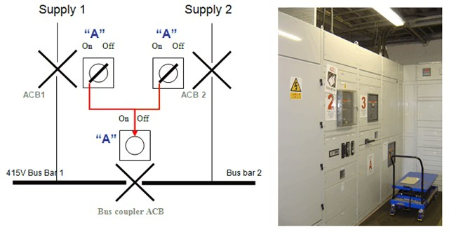
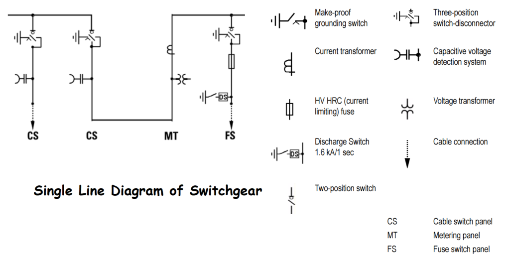
Single line diagram of typical switchgear
A single-line diagram of switchgear is a simplified representation of an electrical power distribution system. It shows the arrangement of various components and equipment in a single line, without showing their physical locations. Here’s a general description of the components you might find in a typical switchgear single-line diagram.
Switchgear Types
Switchgear is a crucial component of electrical power systems that helps control, protect, and isolate electrical equipment. There are various types of switchgear designed for specific applications and voltage levels. Here are some common types of switchgear:
- High-Voltage Switchgear: Designed to operate at high voltage levels, typically above 36 kV. It includes circuit breakers, disconnectors, and protective relays for substations and power transmission systems.
- Medium-Voltage Switchgear: Operates at medium voltage levels, typically between 1 kV to 36 kV. It is commonly used for power distribution in industrial facilities, commercial buildings, and smaller substations.
- Low-Voltage Switchgear: Operates at low voltage levels, typically below 1 kV. It is used for power distribution in buildings, industrial plants, and other facilities.
- Metal-Enclosed Switch gear: Enclosed in metal compartments to provide safety and protection. It is commonly used for high-voltage and medium-voltage applications in substations and power plants.
- Metal-Clad Switch gear: Similar to metal-enclosed switchgear but with individual compartments for each circuit breaker or switch. It provides enhanced safety and maintenance convenience.
- Indoor Switchgear: Designed to be installed inside buildings or enclosures, suitable for applications where space is limited or environmental conditions require indoor installations.
- Outdoor Switchgear: Designed to withstand outdoor environmental conditions, including weather-resistant enclosures and insulation materials.
- Gas-Insulated Switch gear (GIS): Uses gas (such as SF6) as an insulation medium instead of air. GIS is compact and ideal for high-voltage applications where space is a constraint.
- Air-Insulated Switch gear (AIS): Uses air as the insulating medium and is commonly used for low and medium voltage applications.
- Hybrid Switchgear: Combines the features of both GIS and AIS to achieve compactness and flexibility in design.
- Ring Main Units (RMUs): Compact switchgear units used for distribution networks, especially in urban areas with limited space.
- Load Break Switch (LBS) Switch gear: Used for load shedding or sectionalizing, often employed in distribution networks.
The selection of switchgear type depends on factors such as voltage level, application, space availability, environmental conditions, and safety requirements. Each type of switchgear serves a specific purpose in ensuring the reliable and efficient operation of electrical power systems.
Circuit Breaker Types used in Switchgear
Circuit breakers are essential components of switchgear that protect electrical equipment and power systems from overcurrents and faults. Different types of circuit breakers are used in switchgear, each with unique characteristics and applications. Here are some common types of circuit breakers used in switchgear:
- Air Circuit Breaker (ACB): Air circuit breakers use air as the arc quenching medium. They are suitable for low to medium voltage applications and provide reliable protection against short circuits and overloads.
- Oil Circuit Breaker (OCB): Oil circuit breakers use oil as the arc quenching medium. They are commonly used for high-voltage applications and provide effective protection against high current faults.
- Vacuum Circuit Breaker (VCB): Vacuum circuit breakers use a vacuum as the arc quenching medium. They are compact, reliable, and widely used for medium to high voltage applications, including substations and industrial facilities.
- SF6 Circuit Breaker: SF6 (Sulfur Hexafluoride) circuit breakers use SF6 gas as the arc quenching medium. They offer excellent dielectric properties, making them suitable for high-voltage applications, such as power transmission and distribution.
- Magnetic Circuit Breaker: Magnetic circuit breakers use magnetic forces to trip the circuit in case of overcurrents. They are commonly used in low-voltage applications, such as residential and commercial electrical panels.
- Miniature Circuit Breaker (MCB): MCBs are small circuit breakers used in low-voltage electrical systems to protect circuits and appliances from overcurrents and short circuits.
- Molded Case Circuit Breaker (MCCB): MCCBs are designed for higher current applications and are widely used in industrial and commercial installations.
- Residual Current Circuit Breaker (RCCB): RCCBs, also known as ground fault circuit interrupters (GFCIs), are designed to protect against electric shocks and ground faults in residential and commercial applications.
- Earth Leakage Circuit Breaker (ELCB): ELCBs are used to detect small leakage currents to the earth, providing protection against electric shocks and ground faults.
- Electronic Trip Circuit Breaker: These circuit breakers use electronic components for tripping and protection, offering advanced features and precise settings for different applications.
The selection of the appropriate circuit breaker type depends on factors such as the voltage level, current rating, breaking capacity, application, and specific protection requirements. Each type of circuit breaker serves a specific purpose in maintaining the safety and reliability of electrical systems in switchgear installations.
Switchgear Circuit Protection:
The protective circuitry in switchgear is a critical aspect that ensures the safety and reliable operation of power systems. It consists of various protective devices and components designed to detect and respond to abnormal conditions or faults in the electrical network. Some of the key protective circuitry elements in switchgear include:
Circuit breakers and fuses play a crucial role in protecting electrical systems by disconnecting the circuit when the current exceeds a safe level. However, they have limitations in detecting certain critical faults, such as unbalanced currents or high electrical demand. They cannot distinguish between short circuits and high demand situations.
To address these limitations, more advanced protection schemes like the Merz-Price circulating current scheme and distance relays are used. The Merz-Price scheme relies on Kirchhoff’s current law and uses identical current transformers placed at opposite ends of a conductive path, such as a transformer winding or motor winding. Any imbalance in currents is detected, and circuit breakers are tripped to isolate the device, providing effective protection.
Distance relays, on the other hand, are employed in long transmission lines where short circuits may appear similar to normal loads due to impedance limitations. These relays detect faults by comparing voltage and current on the transmission line. A large current combined with a voltage drop indicates a fault, prompting the relay to take protective action.
By utilizing these advanced protection methods in conjunction with circuit breakers and fuses, electrical systems can achieve enhanced safety and reliability, minimizing downtime and ensuring smooth operations in various applications.
Classification:
Switchgear can be classified based on various factors, providing flexibility in selecting the right equipment for specific applications. Some common classifications include:
- Current Rating: Based on the maximum current the device can safely handle, determining its capacity for switching and protection.
- Interrupting Rating: Indicates the maximum short-circuit current (kAIC) the switchgear can safely interrupt without damage.
- Voltage Class: Segregates switchgear into low voltage (below 1 kV AC), medium voltage (1 kV AC to approximately 75 kV AC), high voltage (75 kV to about 230 kV AC), and extra/ultra-high voltage (above 230 kV) categories.
- Insulating Medium: Classifies switchgear based on the material used for insulation, such as air, SF6 gas, oil, vacuum, and carbon dioxide (CO2).
- Construction Type: Categorizes switchgear based on its design, including indoor, outdoor, industrial, utility, marine, and various enclosure types.
- Draw-Out and Fixed Elements: Differentiates switchgear based on whether its elements are removable (draw-out) or permanently fixed.
- Live-Front and Dead-Front: Describes switchgear based on the arrangement of live parts and access for operation and maintenance.
- Metal-Enclosed (ME) and Metal-Clad (MC): Refers to different types of metal enclosures, with MC switchgear having additional features like removable switching devices and grounded metal barriers.
- Cubicle: Indicates a compartmentalized structure for housing switchgear components.
- Arc-Resistant: Switchgear designed to contain and redirect the arc flash energy during faults, enhancing safety for personnel.
The variety of switchgear classifications allows engineers and operators to tailor their selections to meet specific requirements in terms of voltage, current capacity, safety, and environmental conditions.
Switchgear can also be classified based on the degree of internal separation according to IEC standards. These classifications include:
- No Separation (Form 1): Busbars and functional units are not separated from each other.
- Separation of Busbars from Functional Units (Form 2a, 2b, 3a, 3b, 4a, 4b).
- Separation of External Conductor Terminals from Busbars (Form 2b, 3b, 4a, 4b).
- Separation of External Conductor Terminals from Functional Units but Not from Each Other (Form 3a, 3b).
- Separation of Functional Units from Each Other (Form 3a, 3b, 4a, 4b).
- Separation of External Conductor Terminals from Each Other (Form 4a, 4b).
- Separation of External Conductor Terminals from Their Associated Functional Unit (Form 4b).
Additionally, switchgear can be classified based on the type of interrupting device it uses, such as fuses, air circuit breakers, minimum oil circuit breakers, oil circuit breakers, vacuum circuit breakers, SF6 gas circuit breakers, and CO2 circuit breakers.
Furthermore, switchgear can be categorized based on its operating method, whether it is manually operated, motor/stored energy operated, or solenoid operated.
Switchgear can also be classified based on the type of current it handles, whether it is designed for alternating current (AC) or direct current (DC) applications.
Another classification is based on its application, whether it is used in transmission systems or distribution networks.
Lastly, switchgear can be grouped by its purpose, such as isolating switches (disconnectors), load-break switches, and grounding (earthing) switches. These various classifications offer a comprehensive way to select the appropriate switchgear for specific electrical systems and applications.
Switchgear Safety
Switchgear safety is a critical aspect of electrical system operation, and various measures are implemented to ensure safe operation and prevent accidents. Trapped-key interlocking is one such method used to establish predefined operation sequences. For instance, in scenarios where only one power source is allowed to be connected at a time, the interlock scheme requires the first switch to be opened to release a key that allows the closing of the second switch. This ensures proper sequencing of operations and prevents potential hazards.
Indoor switchgear undergoes type testing for internal arc containment to ensure user safety, especially as modern switchgear can handle large currents. Thermal imaging is commonly used for inspection to assess the system’s condition and predict failures in advance. Partial discharge testing and acoustic emission testing are also employed to detect potential faults and issues.
Temperature sensors are installed in switchgear cables to monitor temperature build-up continuously, while SF6 equipment is equipped with alarms and interlocks to warn against pressure loss and prevent operation in unsafe conditions.
To address the dangers associated with high fault levels, many network operators have specified closed-door operations for earth switches and racking breakers. Some European power companies have even prohibited operators from being in switch rooms during operation. Remote racking systems are available, enabling operators to rack switchgear from a safe distance without the need for arc flash hazard suits.
Continuous maintenance and servicing are essential to keep switchgear systems safe, optimized, and capable of handling high voltages effectively. By implementing these safety measures, switchgear can operate reliably and protect both electrical systems and personnel from potential risks.