Testing high voltage (HV) switchgear is essential to ensure the reliability and safety of the electrical distribution system. Below is a general test procedure for conducting high voltage tests on a 13.8kV switchgear. This procedure is a guide and should be adapted based on the specific equipment and manufacturer’s recommendations. Always refer to the manufacturer’s documentation for the most accurate and detailed information.
To guide the responsible persons in conducting 13.8kV Switchgear HV Tests.
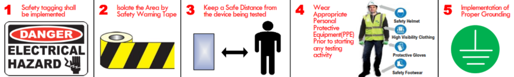
SAFETY PRECAUTIONS – The following Safety precautions shall be taken in consideration prior, during and after conducting the test measurements.
- Safety tagging shall be implemented.
- Isolate the Area by Safety Warning Tape.
- Keep a Safe Distance from the device being tested.
- Wear Appropriate Personal Protective Equipment(PPE) Prior to starting any testing activity.
- Implementation of Proper Grounding.
TEST EQUIPMENTS: VLF HV Test Instrument
Preparation:
- Ensure all personnel involved in the testing are qualified and familiar with safety procedures.
- Review the manufacturer’s documentation, including manuals and drawings, for the switchgear.
- Verify that the switchgear is in a de-energized state, properly isolated, and all safety precautions are in place.
13.8kV Switchgear HV Test Procedure
- Perform VLF High Voltage Test.
1.1 Circuit Breaker ON, Remove all earth wiring and Earth Switch in ON Position: Inject voltage 3uo(3x rated Voltage/√3) for a duration of 1 min. for Phase R with Y+B earthed. Refer to the below image:
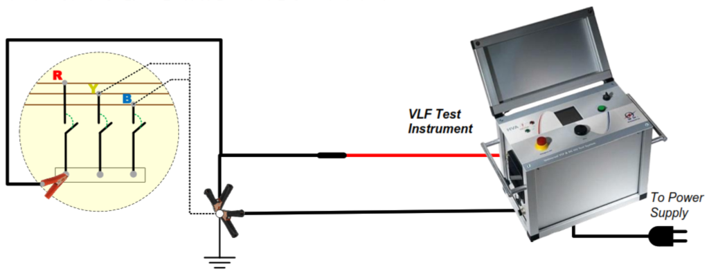
1.1.2 Repeat the above Procedure for the remaining 2 phases Y and B.
1.1.3 Record the Leakage current for each phases.
1.1.4 The measured leakage current should be as per the factory test value (< 10 microA).
1.2 Circuit Breaker OFF, Remove all earth wiring and Earth Switch in ON Position: Inject voltage 3uo(3x rated Voltage/√3) for a duration of 1 min. for Phase R with Y+B earthed. Refer to the below image:
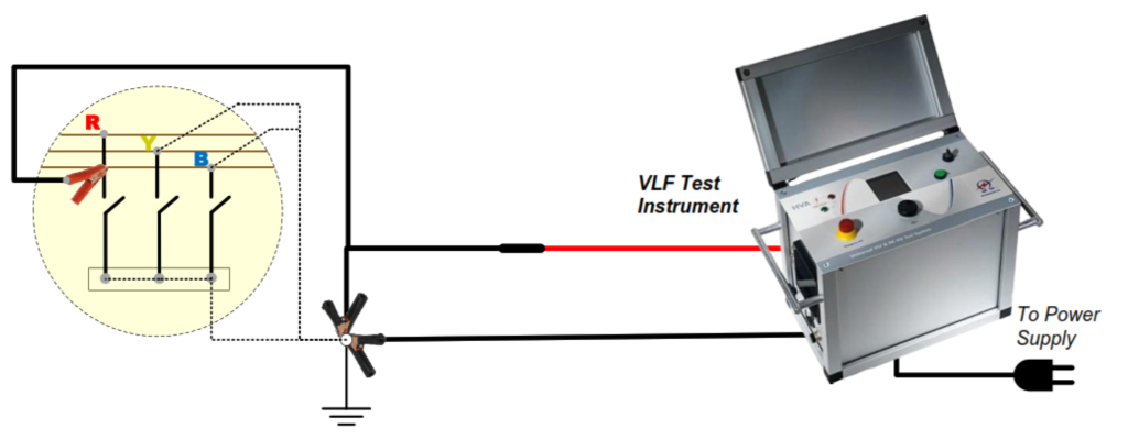
1.2.1 Repeat the above Procedure for the remaining 2 phases Y and B.
1.2.2 Record the Leakage current for each phases.
1.2.3 The measured leakage current should be as per the factory test value (< 10 microA)..
General More Instructions:
- Visual Inspection:
- Inspect the switchgear for any visible signs of damage, wear, or contamination.
- Check for loose connections, corrosion, or overheating.
- Confirm proper grounding of the switchgear.
- Insulation Resistance Test:
- Measure the insulation resistance using an insulation resistance tester.
- Measure resistance between phases and between each phase and ground.
- Ensure that insulation resistance values meet or exceed specified limits.
- Dielectric Strength (High-Potential) Test:
- Perform a dielectric strength test using a high voltage test set.
- Apply the test voltage (typically higher than the rated voltage) and ensure that the insulation withstands the specified duration without breakdown.
- Partial Discharge Measurement:
- Conduct partial discharge measurements using specialized equipment.
- Identify any partial discharges, which may indicate insulation weaknesses.
- Impulse Withstand Voltage Test (if applicable):
- If specified by the manufacturer, perform an impulse voltage test to assess the switchgear’s ability to withstand transient voltages.
- Power Frequency Withstand Voltage Test:
- Apply the rated power frequency voltage for a specified duration to ensure the switchgear can withstand normal operating conditions.
- Verification of Voltage and Current Transformers (if applicable):
- If voltage and current transformers are present, verify their accuracy using a calibrated multimeter or test set.
- Functional Test:
- Verify the functionality of protection relays and other control devices.
- Confirm proper operation of interlocks, alarms, and indicators.
- Thermal Imaging:
- Use a thermal imaging camera to identify any hotspots or abnormalities in the switchgear.
- Pay special attention to connections, busbars, and any components under high voltage stress.
- Documentation:
- Record all test results, including measurements and observations.
- Compare the results with the manufacturer’s specifications.
- Document any deviations from specifications and actions taken to address them.
- De-Energization:
- Safely de-energize the switchgear.
- Restore any safety devices or barriers that were removed for testing.
- Report:
- Prepare a comprehensive test report summarizing the procedures, results, and any recommended actions.
- Include any deviations from specifications and actions taken to address them.
Always prioritize safety during high voltage testing, and follow all safety guidelines and procedures. If you are not familiar with the testing procedures or if there are any doubts, consult with qualified personnel or the equipment manufacturer.