- Implementation and algorithms for inter-RAT handover are vendor specific.
- Different building blocks are provided by 3GPP.
- Downlink instructions through Measurement Control messages.
- Measurement reporting.
- Compressed Mode activation/de-activation.
- Handover command.
- Inter-RAT handover results in specific signalling (RRC) sequence.
This article is about about 3G-2G inter-RAT handover for CS services, and analyses in detail the different vendor specific implementations. All the building blocks regarding the inter-RAT handover are provided by 3GPP, and it is left to the vendors to use these in the best possible way. The next section will analyse in detail the specific RRC signalling sequence that results from the inter-RAT handover.
Phases and algorithms.

The following algorithms will be studied in detail:
Phase 1: Compressed Mode activation algorithm.
Phase 2: inter-RAT handover algorithm.
The figure above gives an overview of the different phases encountered in the inter-RAT
handover. Three phases can be recognised. Phase one is normal 3G operation, the second
phase is 3G Compressed Mode and the last phase is normal 2G operation.
Two different algorithms decide when to go to the next phase: the Compressed Mode activation algorithm decides when to go from phase one to phase two, and the inter-RAT handover algorithm decides when to go from phase two to phase three. These algorithms will be studied for the different vendor implementations.
In phase one the UE is in 3G connected mode, and measures only the 3G intra-frequency neighbours. In the second phase the UE is still in 3G connected mode, and measures not only 3G intra-frequency neighbours but also 2G neighbours. In the last phase the UE is in connected mode GSM and only measures the 2G neighbours. All the little details will be studied in this article.
Compressed Mode principles
- Inter-frequency/inter-system measurements can not be performed continuously without a second receiver.
- Two solutions available.
- Dual receiver mobile.
- One receiver dedicated to each frequency.
- Compressed Mode.
- Create gaps during 3G transmission and reception.
- During these gaps the other frequency/system is measured.
- Gaps are typically (CS services) created with Spreading Factor reduction.
- Dual receiver mobile.
- Compressed Mode has negative impact on interference.
- Spreading Factor reduction (divided by two) has 3db impact on link budget.
- Best to limit maximum number of simultaneous CM users per cell
- Best to limit maximum time in CM (e.g. 12s)
Measurements on a different frequency, such as inter-frequency or inter-RAT measurements, can not be performed continuously without a second receiver. Two solutions are available to tackle this problem.
The best technical solution available is to use a dual receiver mobile. One receiver of the mobile is tuned to perform 3G intra-frequency measurements, the other one is tuned to measure the inter-RAT neighbours. This way both frequencies can be measured at the same time.
Unfortunately, these dual receiver mobiles are quite expensive and are not widely spread. The other solution would be to enter 3G Compressed Mode. During 3G Compressed Mode gaps are created in 3G transmission and reception, and during these gaps the other frequency is measured. 3G Compressed Mode for CS services typically uses spreading factor reduction to create these gaps.
As a consequence, Compressed Mode has a clear negative impact on the interference level. The spreading factor halving has a 3dB impact on the link budget, and because of this the user in Compressed Mode has to raise power. That is why it is best to limit the maximum number of simultaneous users in Compressed Mode per cell, and to put a limit to the maximum amount of time in Compressed Mode.
Compressed Mode vs. dual receiver.

- GSM measurements can be performed in two ways.
- Compressed Mode.
- Dual receiver.
- Dual receiver capability can be found in “RRC Connection Setup Complete” message
(3GPP TS 25.331).
As mentioned before two possibilities are available to perform inter-RAT measurements: using a dual receiver mobile or using Compressed Mode. The dual receiver capability can be found back in the signalling, to be more specific, in the ‘RRC Connection Setup Complete message’ containing details on the UE capabilities. This is indicated in the figure above.
Compressed Mode implementation.
3G Compressed Mode:
- Creation of 3G gaps for GSM measurements.
- By compressing 10ms radio frames.
- This requires higher instantaneous 3G transmit power during Compressed Mode.
- Gaps can range in length from 3 up to 14 time slots.

The figure shows more details on the implementation of 3G Compressed Mode. Gaps have to be created in 3G transmission and reception, and during these gaps GSM measurements can be performed. These gaps are created by compressing the normal 10ms radio frames. The figure above shows both normal 10ms radio frames (green) and compressed 10ms radio frames (red).
Compressing radio frames means the same data has to be transmitted in less time, and as a consequence a higher instantaneous 3G transmit power will be needed during Compressed Mode. The gaps created during Compressed Mode can have different lengths, ranging from 3 up to 14 time slots.
Compressed Mode implementation.
Transmission Gap Length (TGL):
- Number of consecutive idle slots (3, 4, 5, 7, 10 0r 14).
- Two possibilities for Transmission Gap placement.
- Single-frame method: Transmission Gap occurs in one radio frame.
- Double frame method: Transmission Gap divided over two consecutive radio frames.
- At least 8 time slots should be transmitted in every radio frame.

The Compressed Mode gaps can have different lengths. The number of consecutive idle time slots can be 3, 4, 5, 7, 10 or 14, and is called the Transmission Gap Length {TGL). The transmission gap placement can be done in two different ways: single-frame method or double-frame method.
In the single-frame method the transmission gap occurs in one radio frame. Since at least eight time slots should be transmitted in every radio frame, this means the single-frame method allows a maximum gap of seven time slots. In the double-frame method the transmission gap is divided over two consecutive radio frames, and this allows the use of the maximum transmission gap of 14 time slots.
Compressed Mode parameters.
- A Transmission Gap pattern consists of one or two Transmission Gaps.
- The following parameters describe the Transmission Gap pattern:
- TGSN: Transmission Gap starting Slot Number.
- TGL; Transmission Gap Length, expressed in number of Time Slots.
- TGD: Transmission Gap start Distance, expressed in number of Time Slots.
- TGPL: Transmission Gap Pattern Length, expressed in number of radio frames.
- Several Transmission Gap patterns can be defined.
The figure above can be found in the 3GPP specifications TS 25.215, and gives an overview of the available Compressed Mode parameters. As one can see, a Transmission Gap Pattern consists of one or two Transmission Gaps, and can be described by the following parameters: TGSN, TGL, TGD and TGPL.
The exact meaning of these parameters is explained in the above. Several Transmission Gap Patterns can be defined, each serving a specific purpose (e.g. GSM RSSI measurements, BSIC decoding). For optimisation purposes it is not important to know in detail all these Compressed Mode parameters.
Compressed Mode triggers.
- Five different Compressed Mode triggers.
- CPICH Ec/No
- CPICH RSCP.
- Downlink DCH power.
- Uplink Tx power.
- Uplink DCH quality.
- The complete set might not be supported by all vendors.
- Most popular: CPICH Ec/No and CPICH RSCP.
Compressed Mode is needed to measure the GSM neighbours, and will normally result in an inter-RAT handover to GSM. The main reason to go to Compressed Mode is the deterioration of the 3G radio conditions. Five different Compressed Mode triggers are available to detect this situation: CPICH Ec/No, CPICH RSCP, downlink OCH power, uplink transmit power and uplink DCH quality.
However, this complete set of Compressed Mode triggers is not supported by all vendors. Most popular triggers are CPICH Ec/No and CPICH RSCP.
Implementation vendor 1.
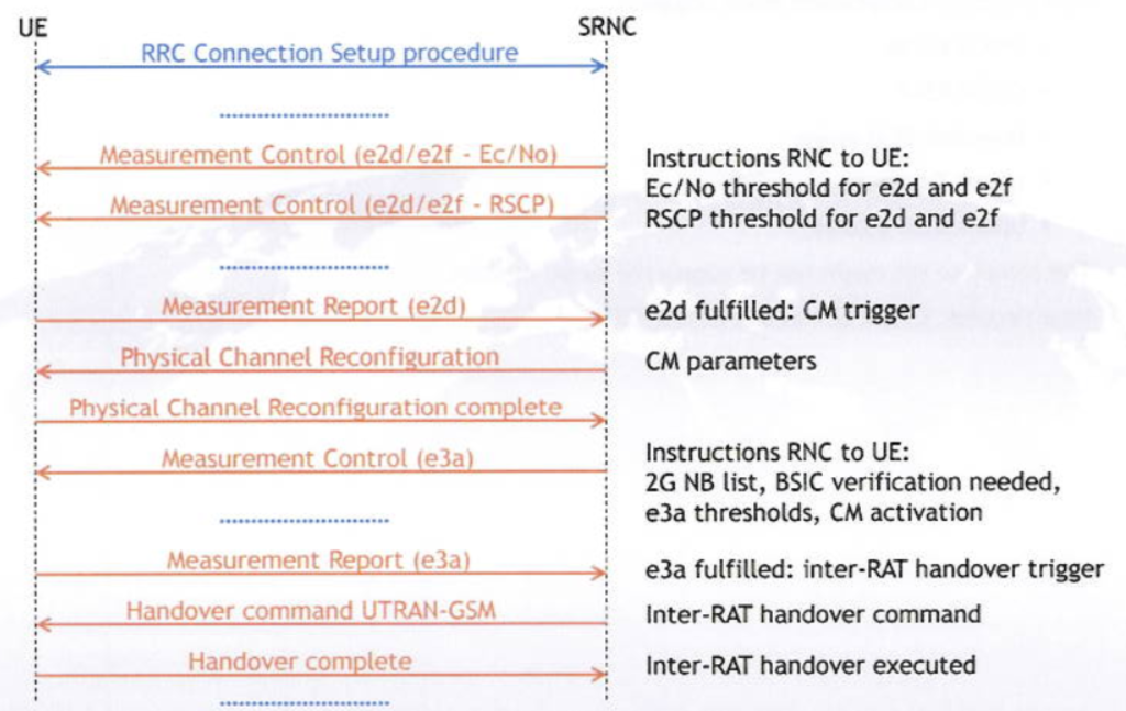
This above picture shows the inter-RAT handover implementation for vendor 1. All relevant RRC messages are indicated in red. This is the vendor specific signalling sequence related to inter RAT handover.
Right after the transition from idle mode to connected mode, the UE should receive several Measurement Control messages containing instructions from the serving RNC on Compressed Mode triggers.
For this vendor 1 implementation, one Measurement Control message contains
the event 2d and event 2f thresholds for the CPICH Ec/No, another Measurement Control
message contains the event 2d and event 2f Thresholds for the CPICH RSCP.
Event 2d means that all cells in the active set have bad Ec/No, or all cells in the active set have bad RSCP. This is the trigger to go to Compressed Mode. Event 2f means one cell is available in the active set with good RSCP or good Ec/No, and Compressed Mode should be left again.
More details on these events can be found in the following sections below. At a certain moment 3G radio conditions get worse, and Compressed Mode is triggered. This is done with a Measurement Report for the event 2d.
The physical Channel Reconfiguration procedure follows containing all Compressed Mode parameters. This procedure does not activate Compressed mode yet. The first Measurement Control message right after the Physical Channel Reconfiguration procedure contains additional instructions regarding the inter-RAT handover.
This Measurement Control message contains the 2G neighbour list, tells the UE to verify the BSIC of the measured 2G neighbours, defines the new event 3a which is the actual inter RAT handover trigger and activates Compressed Mode. Event 3a means that all 3G cells in the active set are bad, but at the same time there is a good 2G neighbour available. More details on this event can be found in the next sections.
At a certain moment during Compressed Mode, 3G gets really bad and suitable 2G alternatives are available. This triggers the Measurement Report for the event 3a. This Measurement Report is sent to the serving RNC and triggers the inter-RAT handover command to the best available 2G neighbour. Once the inter-RAT handover is completed, the Handover complete message is sent by the UE in the uplink on 2G.
Event 2d ThldEcNo – all cells in AS bad.
- Measurement Report 2d: event 2d must be fulfilled for duration ttt2d.
- Enter event 2d: CPICHall) < ThldEcNo – Hyst2d/2.
- Leave event 2d i): CPICH(best) > ThldEcNo + Hyst2d/2.
- Trigger to enter Compressed Mode.

All details on the event 2d with Ec/No threshold can be found in the figure above. Event 2d means that all cells in the active set are bad, in this case below a specific Ec/No threshold. Since a hysteresis Hyst2d is available, the event 2d can be entered and left at different levels.
The difference in Ec/No between entering and leaving the event 2d is Hyst2d, as can be seen on the figure. When all cells in the active set left the green window (enter e2d), a timer tttZd is started. If event 2d is fulfilled during the complete duration of the timer, a Measurement Report e2d will be sent at timer expiry.
If during the timer ttt2d one of the cells in the active set is entering the red window (leave e2d), e2d is not fulfilled anymore and the Measurement Report e2d is not sent. Event 2d is one of the triggers to enter Compressed Mode, in this case because of bad Ec/ No.
Event 2d ThldRSCP · all cells in AS bad.
- Measurement Report 2d: event 2d must be fulfilled for duration ttt2d.
- Enter event 2d: CPICH(all) < ThldRSCP – Hyst2d/2.
- Leave event 2d: CPICH(best) > ThldRSCP + Hyst2d/2.
- Trigger to enter Compressed Mode.
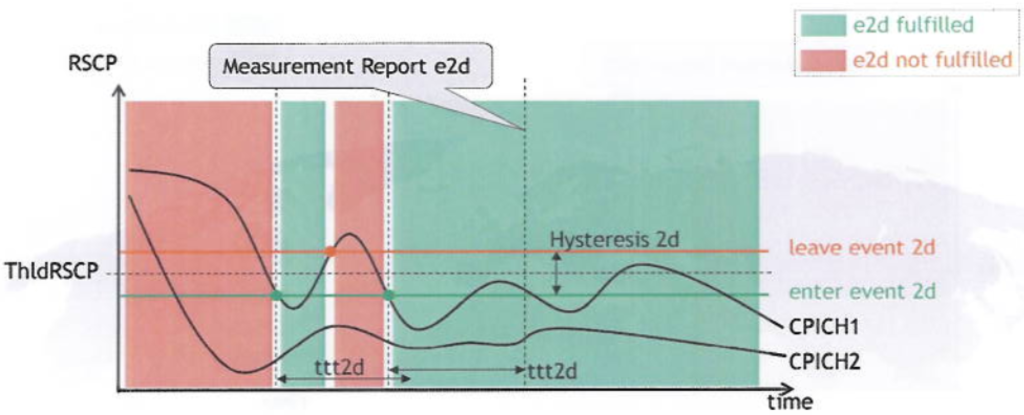
All details on the event 2d with RSCP threshold can be found in the figure above. Event 2d means that all cells in the active set are bad, in this case below a specific RSCP threshold. Since a hysteresis Hyst2d is available, the event 2d can be entered and left at different levels.
The difference in RSCP between entering and leaving the event 2d is Hyst2d, as can be seen on the figure. When all cells in the active set left the green window (enter e2d), a timer ttt2d is started. If event 2d is fulfilled during the complete duration of the timer, a Measurement Report e2d will be sent at timer expiry.
If during the timer ttt2d one of the cells in the active set is entering the red window (leave e2d), e2d is not fulfilled anymore and the Measurement Report e2d is not sent. Event 2d is one of the triggers to enter Compressed Mode, in this case because of bad RSCP.
Event 2f ThldEcNo – good cell in AS.
- Measurement Report 2f: event 2f must be fulfilled for duration ttt2f.
- Enter event 2f: CPICH(best) > ThldEcNo + Hyst2f/2.
- Leave event 2f: CPICH(all) < ThldEcNo – Hyst2f/2.
- Trigger to leave Compressed Mode.
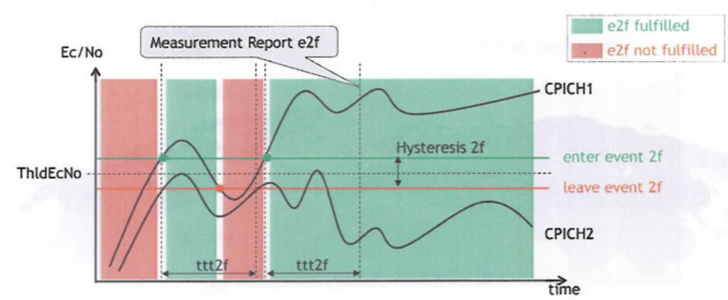
All details on the event 2f with Ec/No threshold can be found in the figure above. Event 2f means that one of the cells in the active set is getting good again, in this case above a specific Ec/No threshold. Since a hysteresis Hyst2f is available, the event 2f can be entered and left at different levels.
The difference in Ec/No between entering and leaving the event 2f is Hyst2f, as can be seen on the figure. When one of the cells in the active set enters the green window (enter e2f), a timer ttt2f is started. If event 2f is fulfilled during the complete duration of the timer, a Measurement Report e2f will be sent at timer expiry.
If during the timer ttt2f the previous mentioned cell is leaving the red window (leave e2f), e2f is not fulfilled anymore and the Measurement Report e2f is not sent. Event 2f is one of the triggers to leave Compressed Mode, in this case because a cell with good Ec/No is available again.
Event 2f ThldRSCP good cell in AS.
- Measurement Report 2f: event 2f must be fulfilled for duration ttt2f.
- Enter event 2f: CPICH(best) > ThldRSCP + Hyst2f/2.
- Leave event 2f: CPICH(all) < ThldRSCP – Hyst2f/2.
- Trigger to leave Compressed Mode.
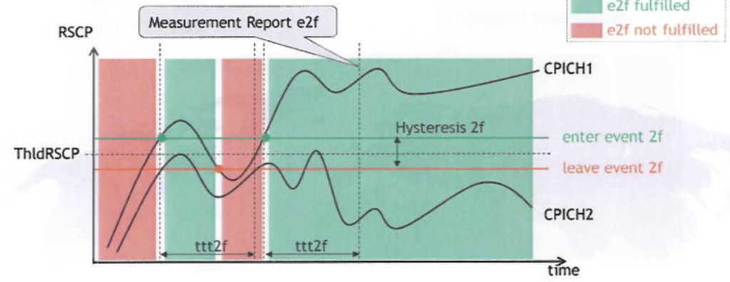
All details on the event 2f with RSCP threshold can be found in the figure above. Event 2f means that one of the cells in the active set is getting good again, in this case above a specific RSCP threshold. Since a hysteresis Hyst2f is available, the event 2f can be entered and left at different levels.
The difference in RSCP between entering and leaving the event 2f is Hyst2f, as can be seen on the figure. When one of the cells in the active set enters the green window (enter e2f), a timer ttt2f is started. If event 2f is fulfilled during the complete duration of the timer, a Measurement Report e2f will be sent at timer expiry.
If during the timer ttt2f the previous mentioned cell is leaving the red window (leave e2f), e2f is not fulfilled anymore and the Measurement Report e2f is not sent. Event 2f is one of the triggers to leave Compressed Mode, in this case because a cell with good RSCP is available again.
Measurement control (e2d/e2f – Ec/No) – Logfile.
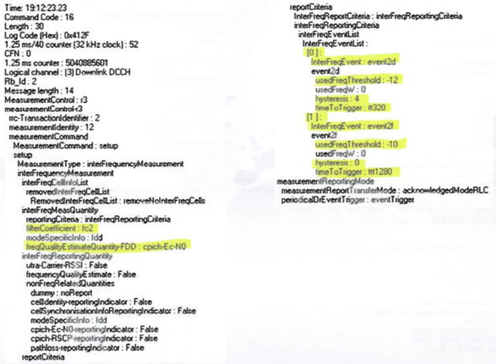
The figure above shows the content of a Measurement Control message from a log file declaring e2d and e2f thresholds for Ec/No. The important information is marked. One can recognise the filter coefficient that was discussed before, and all other event related parameter values.
Measurement control (e2d/e2f – RSCP) – Logfile.
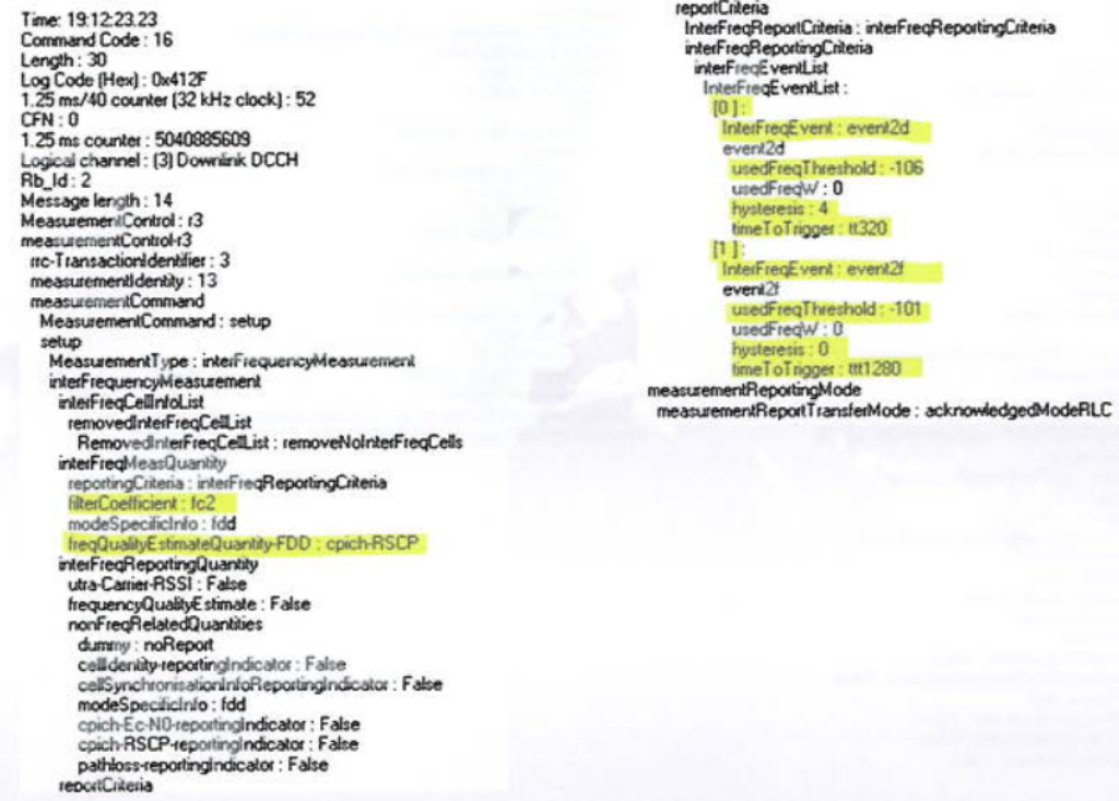
The figure above shows the content of a Measurement Control message from a log file declaring e2d and e2f thresholds for RSCP. The important information is marked. One can recognise the filter coefficient that was discussed before, and all other event related parameter values.
Event 3a – all cells in AS bad but good 2G NB.
- Measurement Report 3a: event 3a must be fulfilled for duration ttt3a.
- Enter event 3a: [CPICH(all)< ThLdRSCP3G -Hyst3a/2] and GSM BCCH>ThldRSSI2G+Hyst3a/2].
- Leave event 3a: [CPICH(best)>ThLdRSCP3G+Hyst3a/2] AND/OR [GSM BCCH<ThLdRSSI2G-Hyst3a/2].
- 3G-2G handover trigger.

All details on the event 3a can be found in the figure above. Event 3a means that all cells in the active set are bad (below a specific RSCP threshold), but at the same time a good 2G neighbour is available with RSSI value above a given threshold. Since a hysteresis Hyst3a is available, the event 3a can be entered and left at different levels. This hysteresis is applied both to the 3G threshold (ThldRSCP3G) and the 2G threshold (ThldRSSI2G).
When all cells in the active set are going below the green level ThldRSCP3G-Hyst3a/2, and at the same time a 2G neighbour is available above ThldRSSI2G+Hyst3a/2, event 3a is entered and the timer ttt3a is started. If event 3a is fulfilled during the complete duration of the timer, a Measurement Report e3a will be sent at timer expiry.
If during the timer ttt3a one of the cells in the active set is going above ThldRSCP3G+Hyst3a/2, or all 2G neighbours drop below ThldRSSI2G Hyst3a/2, e3a is not fulfilled anymore and the Measurement Report e3a is not sent. Event 3a is the actual inter-RAT handover trigger.
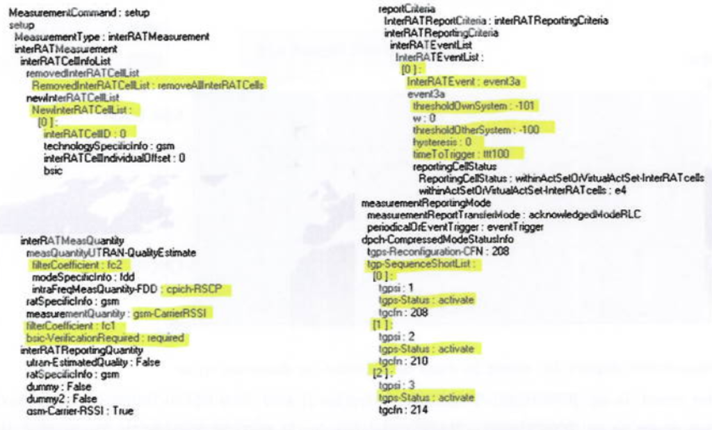
The figure above shows the content of the first Measurement Control message following the Physical Channel Reconfiguration procedure. The first part consists of the GSM neighbour list. Next the filter coefficients and measurement quantities are defined, both for GSM and UMTS, and it is stated that BSIC verification is needed for GSM. After this the event 3a is declared with all needed parameters. At the end of the Measurement Control message Compressed Mode is activated (tgps-Status: activate).
Vendor 1 analysis.
- Every dot represents inter-RAT handover.
- Graph shows average RSCP and Ec/No in a window of 4s preceding inter-RAT handover.
- Behaviour as expected.
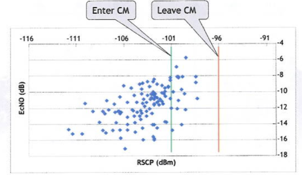
In the graph above the vendor 1 performance is analysed regarding inter-RAT handover. Every dot represents a 3G-2G handover, and the dot indicates the average RSCP and Ec/No values in a window of 4s preceding the actual handover. As one can notice most of the inter-RAT handovers occur below the Compressed Mode trigger that was defined (-101dBm). This behaviour is as expected. Also some inter-RAT handovers are happening above this threshold. This behaviour is also quite normal, since these events occur with average RSCP values below the threshold to leave Compressed Mode. As a conclusion the overall behaviour is as expected.
- Every dot represents dropped call.
- Graph shows average RSCP and Ec/No in a window of 4s preceeding drop.
- Analyse dropped calls where average RSCP below CM trigger.
- Is UE actually in CM?
- If this is not the case for majority of drops: CM threshold should be stronger.
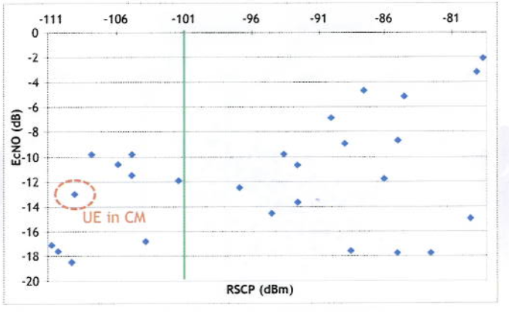
In the graph above the vendor 1 performance is further analysed. In this graph every dot represents a dropped call, and the dot indicates the average RSCP and Ec/No values in a window of 4s preceding the actual drop. In this graph we are especially interested in the dropped calls occurring below the Compressed Mode trigger of -101dBm. Apparently 10 drops take place where the average RSCP is below the Compressed Mode trigger.
Now we check out, by hand, if the UE indeed entered Compressed Mode for each of these drops. Apparently for only one of the dropped calls the UE entered Compressed Mode before. This means the other 9 dropped calls could have been avoided probably, if the UE would have entered Compressed Mode before. This is a strong indication that the Compressed Mode threshold is probably set too weak, and the users are entering Compressed Mode too late leading to unnecessary dropped calls.