Multi-antenna technology, which leverages multiple antennas on either a transmitter or receiver, operates in conjunction with advanced signal processing techniques. This technology introduces the space domain as an additional dimension to the traditional time and frequency domains, significantly enhancing system capacity and coverage.
Due to its complexity, multi-antenna technology has garnered considerable attention since its adoption in LTE, and the associated protocols have been continuously evolving. In 5G, where there are greater demands for capacity and challenges like weak coverage in high-frequency bands, multi-antenna technology has become a fundamental component to address these issues.
The basic concepts of multi-antenna technology can be understood by examining the antenna structure itself.
5G Multi-Antenna Technology and Concepts.
Dipole and Antenna Element.
Dipole and antenna elements are fundamental components of antenna structures.
A dipole consists of two symmetrical conductive wires. As the angle between these wires increases, so does the distance between them. When the total length of the dipole equals half of the wavelength, as depicted in Figure 1, the dipole reaches a resonant state, maximizing radiation efficiency. This type of dipole is known as a half-wave element. Given that millimeter waves (mmWave) have very short wavelengths, the antennas designed for 5G mmWave applications can be quite small, allowing for more antennas to fit within a given space compared to low-frequency antennas.
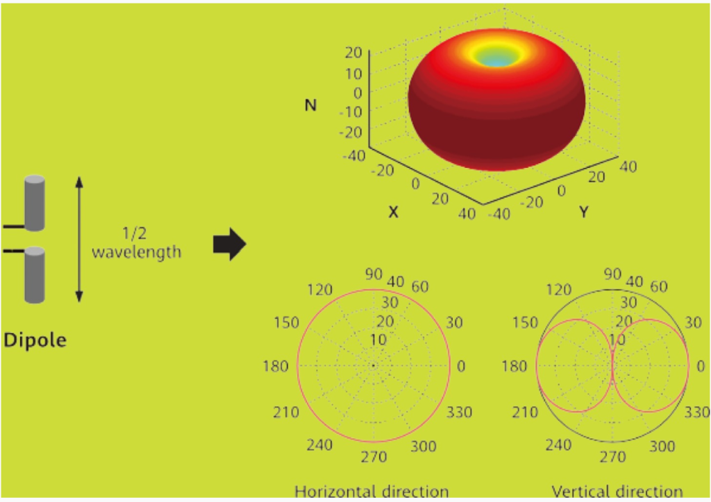
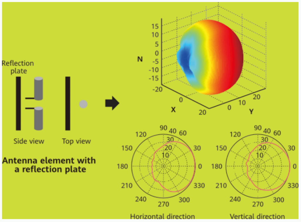
An antenna element is made up of a dipole paired with a reflection plate. The reflection plate causes the signal to superimpose through reflection, enabling directional radiation. Essentially, an antenna element acts as a basic unit within an antenna. During the design of an RF module, multiple antenna elements are often arranged in an array configuration according to the specific requirements. This configuration forms what is known as an antenna array.
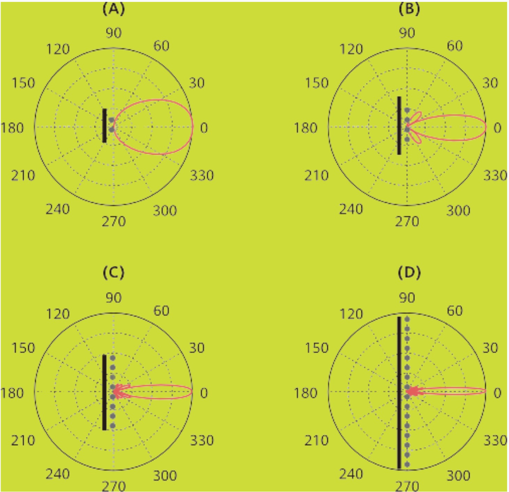
For an antenna array consisting of N antenna elements, the gain in the direction of maximum radiation is calculated as 10log(N) in dB. With just two antenna elements, a beam can be formed. Under identical transmission power conditions, increasing the number of antenna elements results in a narrower beam, as illustrated in Figure 3.
Physical Antenna and Antenna Polarization.
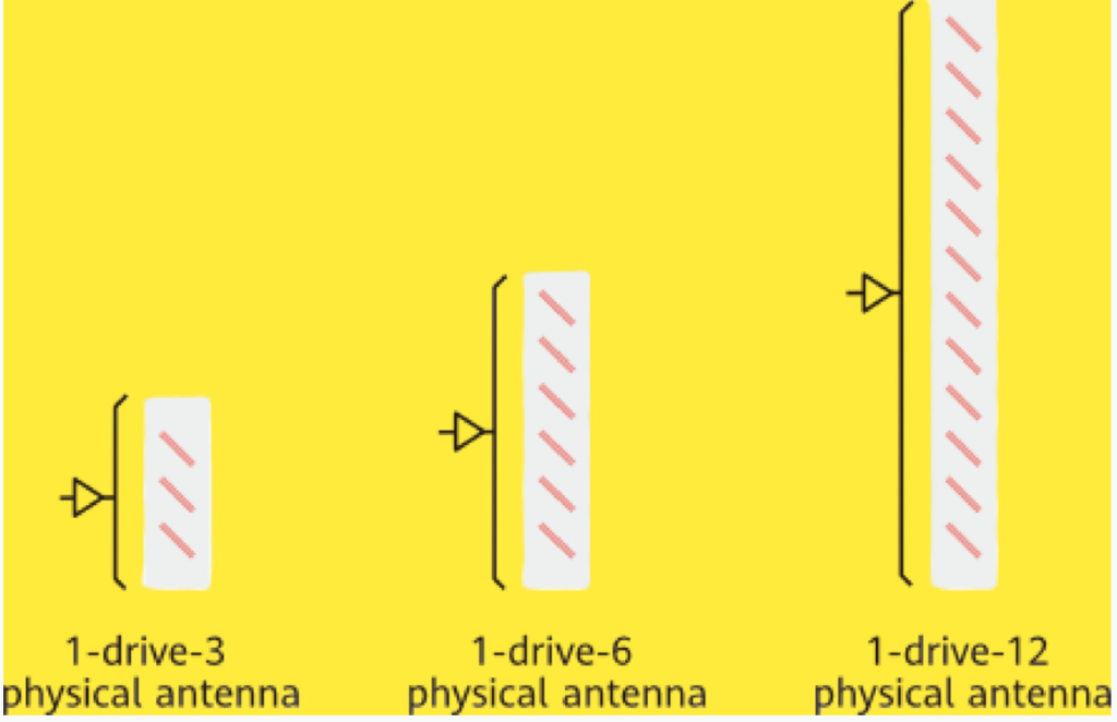
A physical antenna is composed of multiple antenna elements. Typically, all the antenna elements connected to a power amplifier (PA) are collectively known as a physical antenna or an antenna subarray.
As illustrated in Figure 4, physical antennas often follow a configuration referred to as “1-drive-n,” where a single PA is connected to (n) antenna elements. The greater the number of antenna elements in a physical antenna, the higher the gain it achieves.
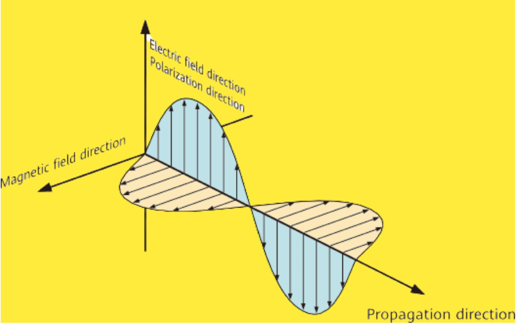
When radio waves are emitted from physical antennas, their electric and magnetic fields are perpendicular to each other in the spatial domain, and both are also perpendicular to the wave’s propagation direction. The direction of the electric field vector in space is generally referred to as the polarization direction of the electromagnetic waves emitted by the antenna.
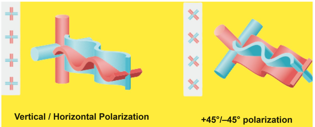
To maximize antenna usage within a limited space and to mitigate multipath fading caused by electromagnetic wave propagation, dual-polarized antennas are widely adopted in the industry. A dual-polarized antenna consists of two antennas with orthogonal polarization directions. These antennas can be classified into vertical/horizontal polarization antennas and +45°/–45° polarization antennas, with the ground serving as the reference plane. Figure 4-3 shows that different colors represent antenna elements oriented in different polarization directions. Currently, +45°/–45° polarization antennas are the most commonly used in the industry.
Antenna Array.
An antenna array is a collection of multiple antenna elements arranged in a specific pattern to enhance signal transmission and reception. In RF modules, planar arrays are commonly used, where the elements are arranged in a rectangular grid on a flat surface. This configuration allows the array to achieve beamforming gains both horizontally and vertically, which improves the signal’s directionality and strength.
- Horizontal Arrangement: Antenna elements aligned horizontally focus the signal in the horizontal plane, enhancing horizontal coverage.
- Vertical Arrangement: Elements aligned vertically focus the signal in the vertical plane, improving vertical coverage.
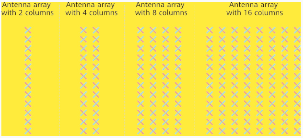
A two-column antenna array, where elements are only arranged vertically, provides vertical gains, meaning it can effectively direct signals up and down. In contrast, more complex arrays with elements arranged both horizontally and vertically enable three-dimensional beamforming, covering a wider area and offering better signal strength and directionality in both planes. This capability is crucial for optimizing the coverage and performance of RF modules.
Antenna Polarization:
- Single Polarization: When considering only one polarization direction, the number of antenna columns is usually 1, 2, 4, or 8, depending on the design.
- Dual Polarization: When two polarization directions (e.g., horizontal and vertical) are considered, the total number of antenna columns doubles, resulting in 2, 4, 8, or 16 columns.
TX/RX Channel (TRX).
Concept of TRX
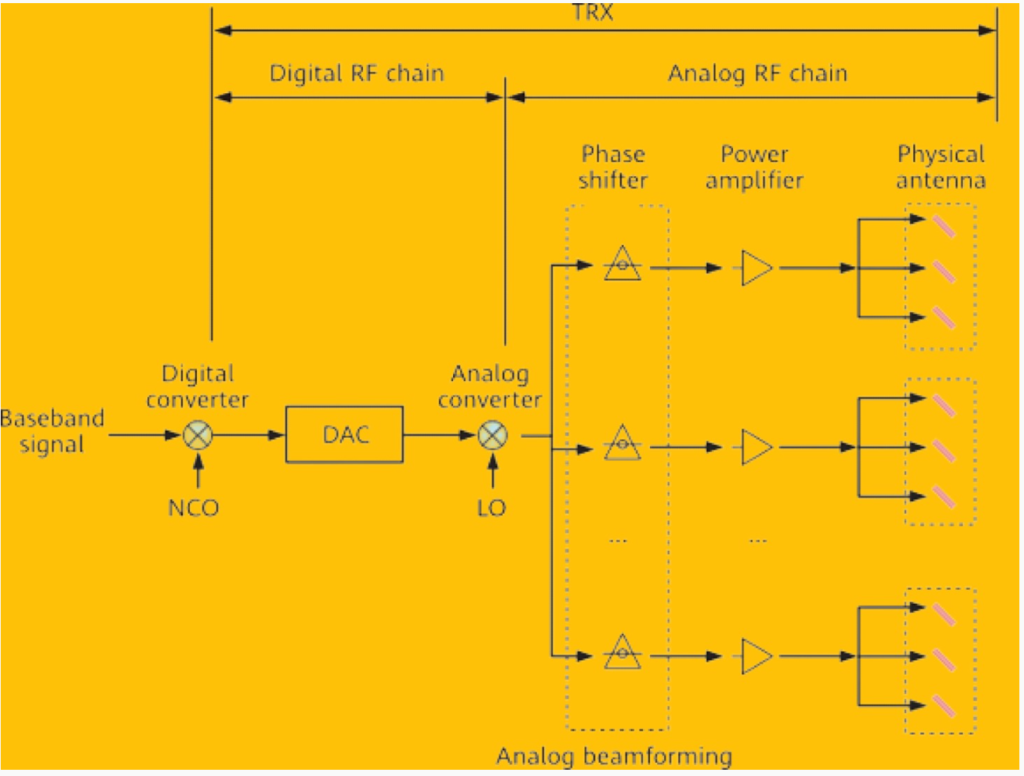
In a wireless communication system, TX/RX channels (TRXs) are essential components that handle the transmission and reception of signals between baseband processing and physical antennas. At the transmission (TX) end, baseband signals are modulated onto high-frequency carriers and sent into the radio propagation environment. At the reception (RX) end, the signals undergo a reverse process, converting them back to baseband for further processing. A TRX includes both digital and analog RF chains that work together to manage this process.
- Digital RF Chains: Handle digital signal processing tasks like modulation, coding, and beamforming.
- Analog RF Chains: Manage the conversion between digital signals and analog RF signals, including amplification and filtering.

Relationship Between TRX and Physical Antenna
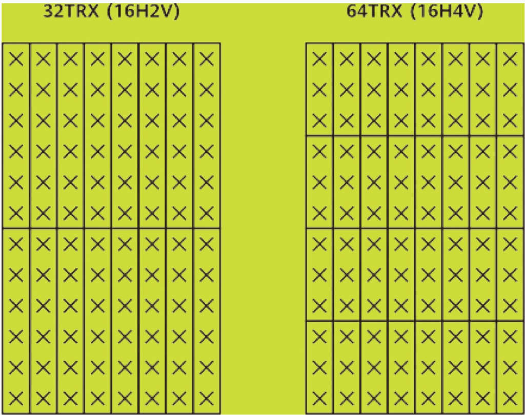
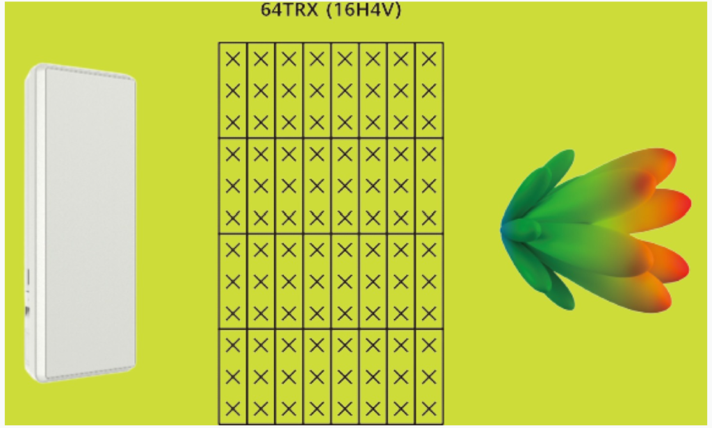
Consider an example of a 64TRX (16H4V) RF module operating in a low-frequency band. This module has 64 physical antennas arranged in a grid pattern, each antenna driven by a corresponding TRX. The 64 physical antennas are divided into 32 grids, with each grid containing two antennas polarized at +45° and -45°.
- Horizontal Coverage (16H): The 16 antennas in each horizontal row can process signals from 16 TRXs, providing horizontal beamforming gains. This setup enhances coverage in the horizontal plane.
- Vertical Coverage (4V): The 4 antennas in each vertical column process signals from 4 TRXs in a single polarization direction, enabling vertical beamforming gains.
The coverage capability of an RF module is often described by the notation mHnV, where m indicates the horizontal TRX count and n the vertical TRX count. A higher m leads to greater horizontal beamforming gains, while a higher n results in greater vertical beamforming gains.
TRX and Beamforming in Low and High Frequency Bands
Low-Frequency Bands (e.g., sub-6 GHz in 5G):
Digital Beamforming: RF modules with 32TRX/64TRX configurations typically use many digital RF chains. By adjusting the weights of these digital RF chains, the system can control the amplitude and phase of signals. This allows for the formation of narrow, directed beams that can be spatially multiplexed to increase channel capacity and improve spectral efficiency.
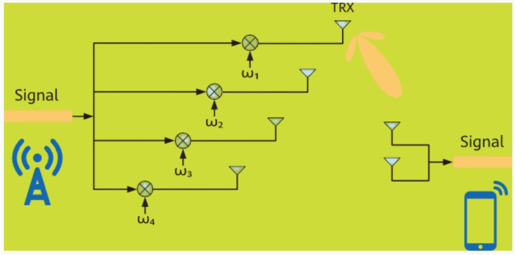
3D Beamforming: In configurations where m > 1 and n > 1, each TRX can independently adjust its signal weights. This flexibility allows beams to be formed dynamically in various directions, enabling three-dimensional beamforming that covers both horizontal and vertical planes.
High-Frequency Bands (e.g., mmWave in 5G):
- Hybrid Beamforming: High-frequency bands like mmWave require a different approach due to the large transmission losses and shorter wavelengths. Here, the focus shifts to maximizing coverage. Typically, there are fewer digital RF chains (e.g., 2 or 4 TRXs) compared to the number of analog RF chains. Each digital RF chain corresponds to multiple analog RF chains, which manage the large number of physical antennas.
- Analog and Digital Beamforming: To optimize performance, both analog and digital beamforming techniques are combined. Analog beamforming adjusts the phase and amplitude of signals at the antenna level, while digital beamforming manages the overall signal direction. This hybrid approach balances the benefits of both technologies, achieving efficient beamforming with fewer digital RF chains.
Trade-offs Between 32TRX and 64TRX
- 32TRX (16H2V): Each TRX drives more antenna elements, leading to a higher gain per element but fewer overall TRXs. This setup provides strong coverage in specific directions but fewer directional beamforming capabilities.
- 64TRX (16H4V): With more TRXs, this configuration offers better beamforming flexibility and coverage in multiple directions. However, it is larger, heavier, and more expensive.
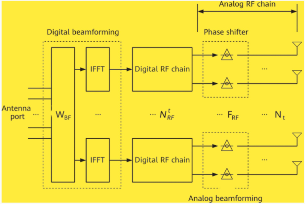
- WBF: weight matrix for digital beamforming.
number of digital RF chains.
- FRF: weight matrix for analog beamforming.
- Nt: number of analog RF chains, that is, number of physical antennas.
In summary, the design and configuration of TRX channels, along with the integration of beamforming techniques, play a critical role in optimizing the performance of RF modules in both low and high-frequency bands in 5G networks.
Multi-Antenna Gains.
Multi-antenna systems in 5G networks offer various types of gains that enhance signal quality, interference management, and overall system capacity. These gains are achieved through techniques like beamforming, spatial diversity, and spatial multiplexing.

1. Array Gains: Enhancing Signal Strength (SNR)
Array gains refer to the improvement in the average signal-to-noise ratio (SNR) when multiple antennas work together to process signals.
- Uncorrelated Noise: The noise picked up by different antennas is typically uncorrelated, meaning that when signals from multiple antennas are combined, the noise power remains relatively unchanged.
- Correlated Signals: The signals received by different antennas are often correlated, which means their power increases when combined, leading to a stronger overall signal.
- Impact of More Antennas: The more physical antennas in the array, the greater the signal strength when signals are combined in the same direction. Additionally, if each physical antenna has more elements, the signal strength is further enhanced after superimposition.
2. Interference Suppression Gains: Improving SINR
Interference suppression gains focus on increasing the average signal-to-interference-plus-noise ratio (SINR) by mitigating interference.
- Multi-Antenna Algorithms: Techniques like digital beamforming and interference rejection combining (IRC) are employed to cancel or reduce interference, thereby improving SINR.
- Narrower Beams: With more physical antennas, beams can be made narrower, which enhances the system’s ability to suppress interference. This is especially important in 5G, where intra-frequency networking can lead to strong interference.
- 5G and Interference: Narrow beams in 5G are effective in reducing interference, which is critical given the dense deployment and frequency reuse in these networks.
3. Spatial Diversity Gains: Reducing SNR Fluctuation
Spatial diversity gains help stabilize the SNR by reducing the impact of radio channel fading.
- Radio Channel Fading: Fading causes the SNR of received signals to fluctuate. However, because signals from different antennas are unlikely to experience deep fading simultaneously, combining them reduces the likelihood of significant SNR drops.
- Diversity Advantage: By using multiple antennas, the system can combine signals in a way that minimizes the probability of deep fades, leading to more stable signal quality.
4. Spatial Multiplexing Gains: Enhancing System Capacity
Spatial multiplexing gains allow for an increase in the number of transmission layers, thereby boosting system capacity.
- Degrees of Freedom (DOFs): Multiple antennas provide more DOFs in the space domain, enabling the system to support more parallel transmission layers. This directly increases the data-carrying capacity of the network.
- Low Frequency Bands: These bands often have limited bandwidth and high interference, so capacity is primarily improved by leveraging interference suppression and spatial multiplexing gains. Digital beamforming plays a crucial role in reducing inter-beam interference, enabling efficient reuse of time-frequency resources across different spatial layers.
5. Application in Different Frequency Bands
- Low-Frequency Bands: Due to smaller bandwidth, higher interference, and limited capacity, gains are focused on interference suppression and spatial multiplexing. Digital beamforming helps mitigate interference and enhances spectral efficiency.
- High-Frequency Bands (mmWave): These bands experience fast fading and limited coverage. To overcome these challenges, systems rely on array gains and spatial diversity gains.
- Downlink: Signals are superimposed in the same direction to increase strength.
- Uplink: Combining signals from different antennas reduces the probability of deep fading.
Summary
Multi-antenna gains are crucial for optimizing the performance of 5G networks. Array gains improve signal strength, interference suppression gains enhance SINR, spatial diversity gains stabilize SNR, and spatial multiplexing gains boost system capacity. The application of these gains varies between low and high-frequency bands, with each band having distinct challenges and requiring different optimization strategies.