In LTE, downlink transmission resources are structured in three dimensions: time, frequency, and space. The spatial dimension, which is measured in ‘layers,’ is accessed using multiple antenna techniques for both transmission and reception.
What is LTE Frame Structure?
The LTE frame structure is designed to efficiently organize and manage the transmission of data across the network. It incorporates time, frequency, and space dimensions to optimize resource allocation and ensure robust communication.
Time-Frequency Structure.
The LTE downlink time-frequency resources are organized in a hierarchical manner:
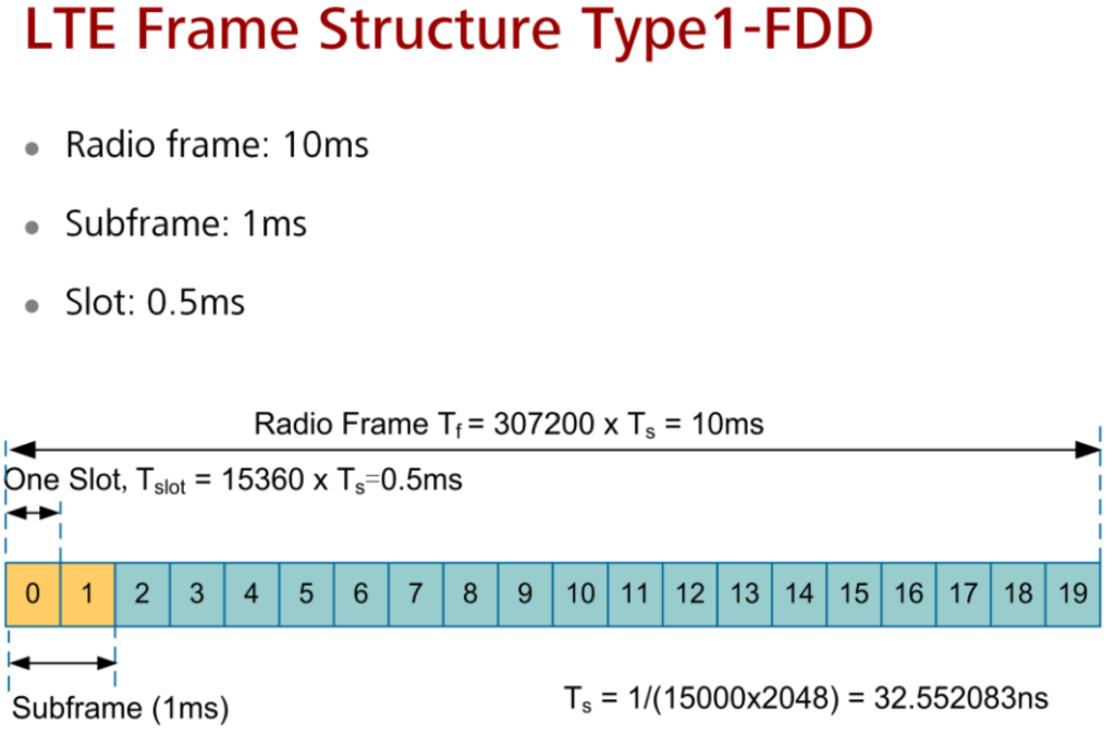
- Radio Frame: The largest unit of time in LTE is the 10 ms radio frame.
- Subframes and Slots: Each radio frame is divided into ten 1 ms subframes. Each subframe is further divided into two 0.5 ms slots.
- OFDM Symbols: Each slot contains seven OFDM symbols when using the normal cyclic prefix. If the extended cyclic prefix is configured, each slot contains six OFDM symbols.
In the frequency domain, the resources are grouped as follows:
- Resource Blocks (RB): A resource block spans 12 subcarriers, occupying a total bandwidth of 180 kHz. The duration of one slot (0.5 ms) is termed a Resource Block.
- Resource Elements (RE): The smallest unit of resource block is the Resource Element, which consists of one subcarrier for the duration of one OFDM symbol.
A resource block contains:
- 84 Resource Elements: When the normal cyclic prefix is used.
- 72 Resource Elements: When the extended cyclic prefix is used.
The detailed structure of these resources can be visualized with a diagram illustrating the arrangement of OFDM symbols and subcarriers within a slot, showing the allocation of resource blocks and resource elements.
Detailed Structure of Resource Blocks in LTE
In LTE, certain resource elements within resource blocks are designated for special functions:
- Synchronization Signals: Used for network synchronization and initial access.
- Reference Signals: Provide channel estimation and measurement.
- Control Signaling: Essential for managing and controlling the communication process.
- Critical Broadcast System Information: Contains important system information that must be broadcast to all UEs.
The remaining resource elements within the resource blocks are used for data transmission. Typically, these data-carrying resource blocks are allocated in pairs, which are paired in the time domain.
LTE Frame Structure Types.
LTE Frame Structure Type 1:
Used in Frequency Division Duplexing (FDD) in paired radio spectrum or for standalone downlink carriers. All subframes are available for downlink transmission.
Get More Details Here: What is FDD Frame Structure?
LTE Frame Structure Type 2:
- Application: Used in Time Division Duplexing (TDD) in unpaired spectrum.
- Basic Structure: The structure of resource blocks (RBs) and resource elements (REs) remains the same as in FDD.
- Subframe Availability: Only a subset of the subframes are available for downlink transmission. The remaining subframes are allocated for uplink transmission or as special subframes.
- Special Subframes: Allow switching between downlink and uplink transmissions and include a guard period in the center to facilitate the timing advance of uplink transmissions.
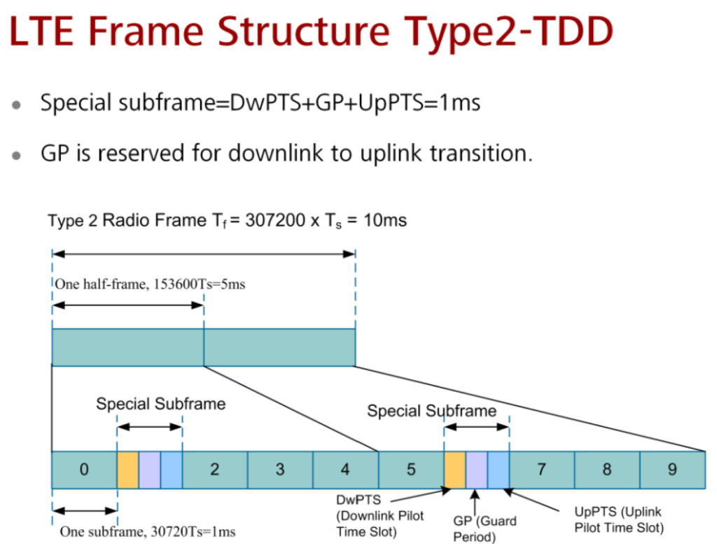
In LTE, each radio frame has a duration of 10 ms and is divided into two half-frames, each lasting 5 ms.
Half-Frame Composition
Each half-frame is further divided into:
- Eight Slots: Each slot is 0.5 ms in length.
- Three Special Fields: These fields together sum up to 1 ms:
- DwPTS (Downlink Pilot Time Slot): Used primarily for downlink transmissions.
- GP (Guard Period): Reserved for transitioning from downlink to uplink transmission.
- UpPTS (Uplink Pilot Time Slot): Used primarily for uplink transmissions.
Type 2 LTE Radio Frame Switching Points.
Frequency Division Duplex (FDD) in LTE
In LTE Frequency Division Duplex (FDD), the subframe allocation is fixed at a 1:1 ratio for downlink (DL) and uplink (UL) transmissions. This setup simplifies the network design but may not always make the most efficient use of the available frequency spectrum, especially when the service requirements for DL and UL are unbalanced.
Time Division Duplex (TD-LTE)
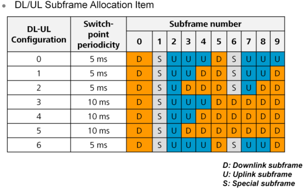
In contrast, TD-LTE offers more flexibility with seven different subframe allocation configurations, ranging from 0 to 6. These configurations can be adjusted to cater to various service types and requirements, enabling a more balanced and efficient use of the frequency spectrum.
Subframe Allocation and Efficiency
By allowing the allocation of subframes to be adjusted based on service demands, TD-LTE can better accommodate the typically higher demand for downlink services compared to uplink services. This dynamic allocation improves overall frequency efficiency and optimizes network performance.
Special Fields in TD-LTE
To minimize network consumption and maximize resource utilization, specific subframes and fields within the radio frame are designated for particular purposes:
- DwPTS (Downlink Pilot Time Slot): Utilized for transmitting downlink channels such as PCFICH (Physical Control Format Indicator Channel), PDCCH (Physical Downlink Control Channel), PHICH (Physical Hybrid ARQ Indicator Channel), PDSCH (Physical Downlink Shared Channel), and P-SCH (Primary Synchronization Channel).
- UpPTS (Uplink Pilot Time Slot): Used for transmitting Sounding Reference Signals (SRS) and PRACH (Physical Random Access Channel) Preamble.
Details of UpPTS:
- Short RACH: Configurable to occupy 1 OFDM symbol.
- SRS (Sounding Reference Signal): Always exists, occupying 1 OFDM symbol.
Subframe Allocation in TD-LTE
- Subframe 1 in all configurations and subframe 6 in configurations with 5ms switch-point periodicity consist of DwPTS, GP (Guard Period), and UpPTS.
- Subframes 0 and 5 along with DwPTS are always reserved for downlink transmission, ensuring consistent downlink performance and resource availability.
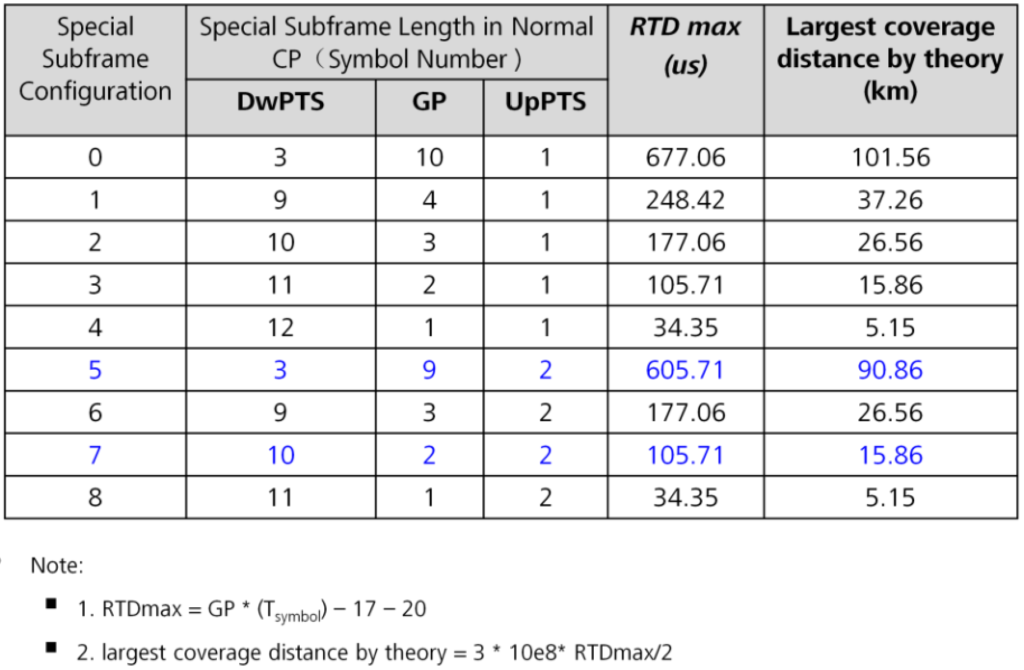
Special Subframe Configuration.
CP(Cyclic Prefix).
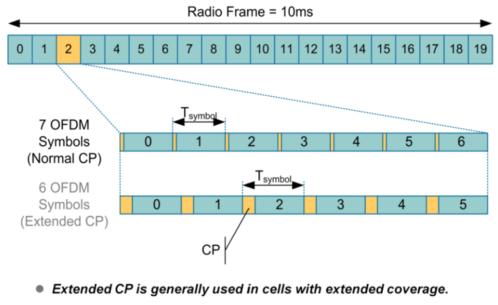
CP Classification and Scenario.
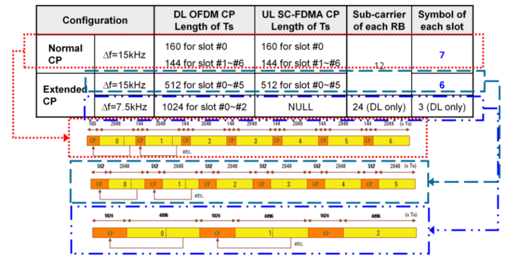
Generally, Normal CP is configured.
For MBSFN, Extended CP is configured.
Extended CP may be configured for the cell with larger radius like wide coverage scenario.
Δf=7.5kHz is available for MBSFN(MBMS over Single Frequency Network), which defined in 3GPP Protocol 8 but applied until 3GPP Protocol 9. Attention: 7.5kHz is only adapted for downlink.