Frequency Division Duplex (FDD) is a method used in wireless communications to separate the uplink and downlink transmissions by using different frequency bands. In LTE, the FDD frame structure is designed to efficiently manage these transmissions to ensure high data rates, low latency, and robust connectivity. The FDD frame structure is divided into several components that organize how data is transmitted and received.
For FDD, LTE uses the Type 1 radio frame structure. In the time domain, the frame is 10 ms long and is sub-divided into 1 ms subframes (numbered 0 to 9) and then further sub-divided into 0.5 ms slots (numbered 0 to 19). The number of OFDM symbols is 7 per slot (14 per subframe) for the normal cyclic prefix and 6 per slot (12 per subframe) for the extended cyclic prefix.
For FDD, 10 subframes are available for downlink transmission and 10 subframes are available for uplink transmissions in each 10 ms interval. Uplink and downlink transmissions are separated in the frequency domain. In half-duplex FDD operation, the UE cannot transmit and receive at the same time while there are no such restrictions in full-duplex FDD.

In the frequency domain, the number of subcarriers is dependent on the channel bandwidth. The LTE OFDM frame scales well because the subcarrier and symbol characteristics are identical for each channel size; therefore, only the number of subcarriers changes with channel bandwidth.
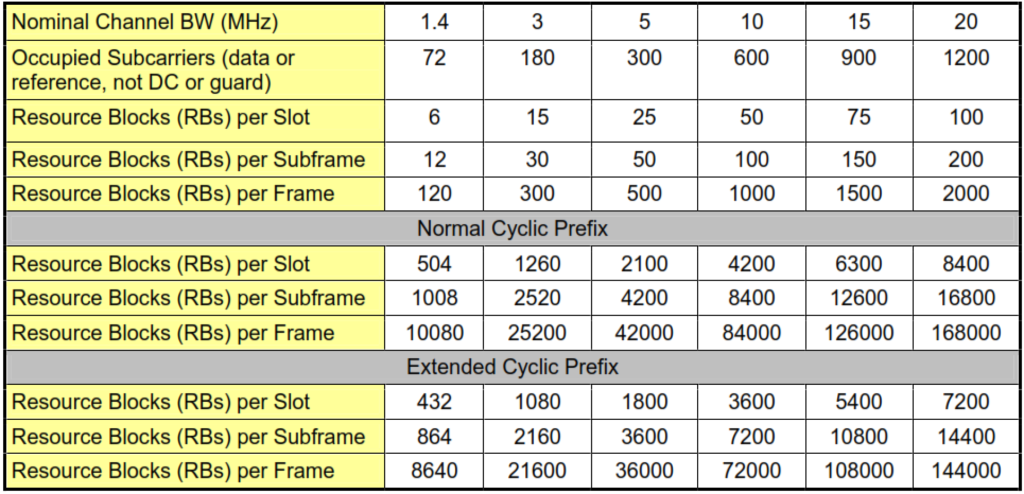
After discounting for the DC and guard subcarriers, the remaining “occupied” subcarriers may be used for bearer, control or reference signals. The following table provides a summary of various parameters which are based on the channel bandwidth.

Thus defined, the frame comprises a matrix of occupied subcarriers (hereafter referred to solely as subcarriers) in the frequency domain and OFDM symbols (hereafter referred to solely as symbols) in the time domain. A resource element (RE) refers to the modulation symbol corresponding to a particular combination of symbol and subcarrier.
Within slots, resource blocks (RB) are defined which correspond to 1 slot in time by 12 subcarriers in frequency9 (84 REs assuming normal cyclic prefix). Ultimately, allocations for data transmissions will be made in pairs of RBs where the RBs will be assigned one from each slot of the subframe and may be non-adjacent (i.e. “distributed” to maximize frequency diversity) or adjacent (i.e. “localized” to exploit frequency selective scheduling). The following figure shows pictorially the Resource Block and Resource Element.

With the explanation of the frame structure provided in this section, an approximate capacity in resource elements per second (RE/sec) can be estimated as follows:
RE/second = subcarriers x (symbols/slot x slots/frame) x frames/second, or
RE/second = RB/slot x symbols/RB x slots/frame x frames/second.
For example, assuming a 10 MHz channel bandwidth and normal cyclic prefix,
RE/second = 600 x (7 x 20) x 100 = 50 x 84 x 20 x 100 = 8.4 M RE/second. The following table shows the number of resource elements and resource blocks per frame for each channel bandwidth.

Already, this table provides some feel for the magnitude of the throughputs which can be achieved. Assuming a bandwidth of 10 MHz and spectral efficiency of 5 bits/RE, the throughput would be 42Mbps (84000 REs/frame x 5 bits/RE x 100fps). This approximation is too coarse to be applied to data throughput since it does not account for layer 1 overheads and retransmissions. Subsequent sections will refine this approximation.
In addition to resource blocks, two other groupings of resource elements are used for allocation purposes. Resource element groups (REGs) are defined as a quadruplet of resource elements. The resource elements are contiguous within a symbol of a RB, excluding REs reserved for reference signals. Control channel elements (CCEs) correspond to a set of 9 REGs.