Inter-eNodeB handovers in LTE networks allow a user to move from one base station (eNodeB) to another. While these handovers are typically conducted over the X2 interface, they can also occur over the S1 interface if the X2 link is not available or configured. When both X2 and S1 links are present, the system prefers using the X2 interface for handovers because it can be more efficient.
Read Also: LTE X2 Handover – Inter-eNodeB Handover over X2 Signaling
Prerequisite of this article: What is S1 Application Part (S1AP)?
When an inter-eNodeB handover occurs over the S1 interface, the process involves several key steps. First, the handover preparation begins. This phase is triggered by the source eNodeB, which is the current base station serving the user. The trigger typically comes after the eNodeB receives a measurement report indicating that the user needs to switch to a different cell to maintain a strong connection. Upon receiving this report, the source eNodeB sends a relocation preparation request to the MME (Mobility Management Entity).
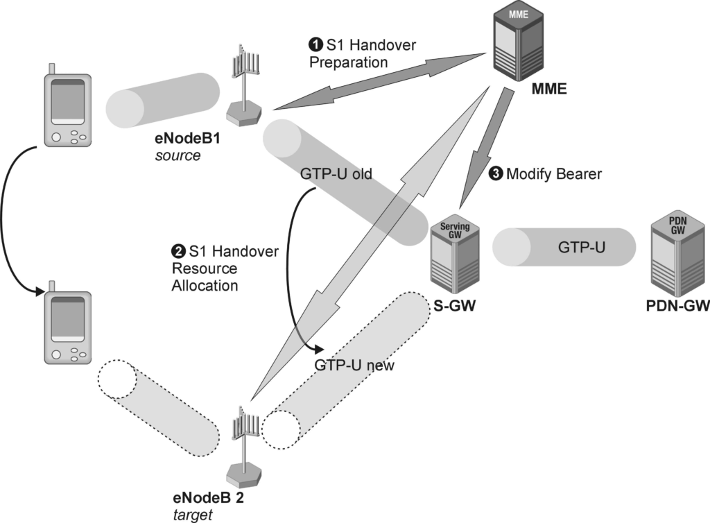
Next is the handover resource allocation phase. The MME, upon receiving the request from the source eNodeB, contacts the target eNodeB to allocate the necessary radio resources for the handover. The target eNodeB then responds with the required parameters, which the MME forwards to the user equipment (UE) in a handover command message. This message instructs the UE to connect to the new target eNodeB.
The final step involves modifying the S1-U bearer. The GTP (GPRS Tunneling Protocol) tunnel on the S1-U interface, which is used to transmit user data, needs to be switched to ensure that the data continues to flow seamlessly from the new target eNodeB. This switching is done by performing a bearer modification procedure on the S11 interface, which is triggered by the MME and executed by the Serving Gateway (S-GW). This ensures that the user’s data sessions remain uninterrupted during the transition.
In telecommunication industry terminology, the handover process is often divided into different legs for performance measurement. The initial phase, where the source eNodeB prepares for the handover, is known as the “outgoing handover” or “outgoing leg.” The subsequent phase, where the target eNodeB allocates resources, is referred to as the “incoming handover” or “incoming leg.” The combined steps of sending the handover required message and the handover request message are collectively termed the “handover preparation phase.”
S1 Handover in LTE.
In LTE networks, a S1 handover refers to the process of transferring a user equipment (UE) from one eNodeB (base station) to another while maintaining ongoing communication.
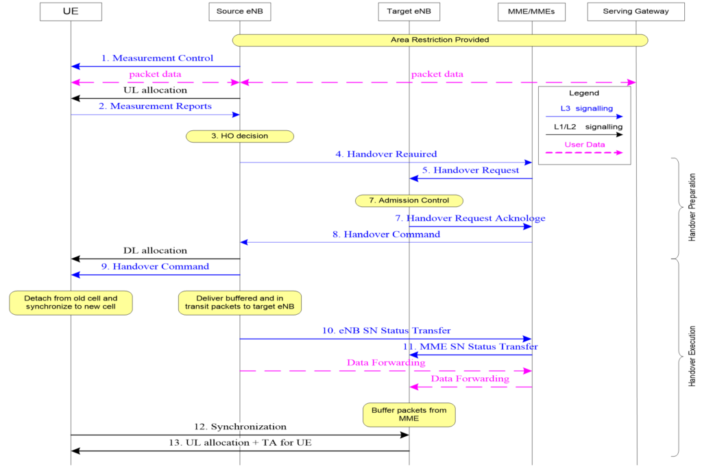
Step 1: S1AP Handover Required.
When the serving eNodeB (base station) detects a change in the downlink (DL) or uplink (UL) quality of an active connection, it initiates a handover process to ensure the user maintains a strong and reliable connection. This detection can come from an RRC (Radio Resource Control) measurement report or internal measurements within the eNodeB.
The eNodeB sends an “S1AP Handover Required” message to the MME (Mobility Management Entity). This message is a crucial part of the handover procedure and is encoded using ASN.1 (Abstract Syntax Notation One) with a procedure code labeled “Relocation Preparation.”
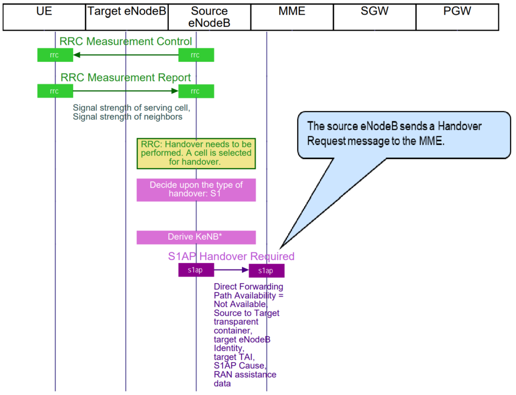
Here are the key components of the “S1AP Handover Required” message:
- Handover Type: Specifies the type of handover, such as an intra-LTE handover, which means the handover is within the LTE network.
- Cause: Indicates the reason for the handover. For example, it might be “handover desirable for radio reasons,” suggesting that the handover is needed to improve radio signal quality.
- Target ID: Contains the identifier of the target eNodeB (the new base station to which the UE will connect) and the target TAI (Tracking Area Identifier), which helps in locating the new cell.
The message also includes a source-to-target TransparentContainer. This container holds all the essential UE capabilities and RRC parameters required to continue the ongoing RRC connection seamlessly after the handover to the target cell.
Step 2: S1AP Handover Request.
Once the MME (Mobility Management Entity) receives the “S1AP Handover Required” message from the source eNodeB, it selects the appropriate transport link to the target eNodeB using its internal routing table. If there are errors in this routing table, and the target eNodeB cannot be reached, the MME sends a handover preparation failure message back to the source eNodeB.
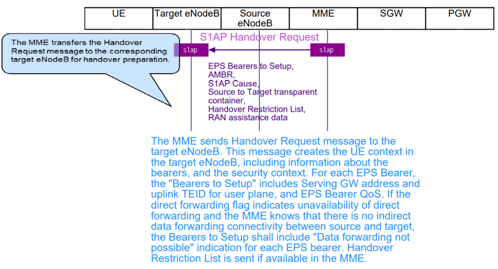
If the target eNodeB is reachable, the MME sends an “S1AP Handover Request” message to the target eNodeB. This message includes:
- Handover Type: Same as in the “Handover Required” message.
- Cause: Reason for the handover, such as improving radio signal quality.
- Source-to-Target TransparentContainer: Contains UE capabilities and RRC parameters needed to continue the connection after the handover.
Additionally, the message includes:
- List of e-RABs (Evolved Radio Access Bearers): Specifies the bearers and their QoS (Quality of Service) parameters for which the S1-U GTP tunnel needs to be switched.
- UE Security Capabilities and Context: Ensures that the security settings (ciphering and integrity protection) are maintained after the handover on the new connection.
Step 3: S1AP Handover Request Acknowledge.
Once the target eNodeB receives the “S1AP Handover Request” message, it allocates the necessary radio resources to take over the UE’s RRC connection. The target eNodeB needs to inform the UE about these resources, so it prepares an RRC handover command. This command is actually an RRC connection reconfiguration message that includes information like the physical cell identity of the target cell.
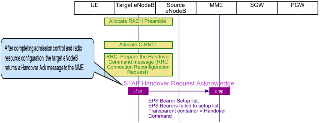
To communicate this to the source eNodeB, the target eNodeB packages the RRC handover command within the target-to-source TransparentContainer. This container, along with E-RAB parameters, is then sent to the MME in an “S1AP Handover Request Acknowledge” message. This message is encoded as an ASN.1 S1AP successful outcome message with the procedure code “Handover Resource Allocation.”
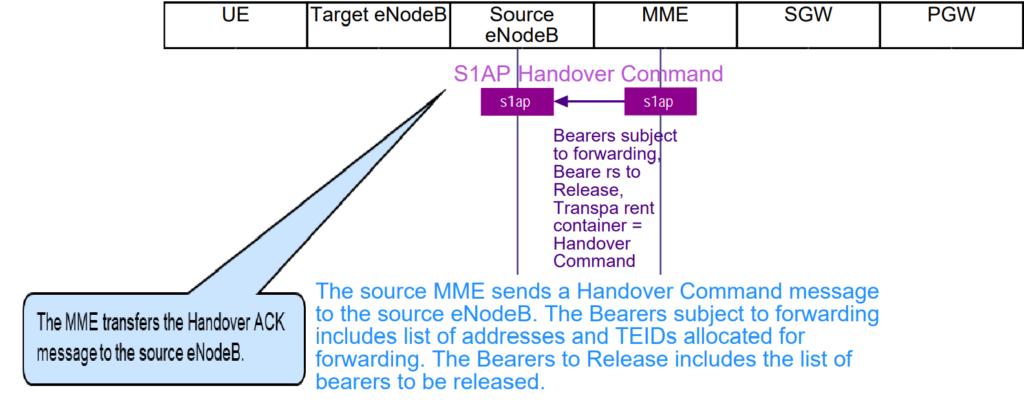
The MME then forwards this information to the source eNodeB, completing the necessary preparations on the incoming leg of the handover. This ensures that the UE receives all the required details to successfully transition to the new cell managed by the target eNodeB.
Step 4: S1AP Handover Command
After receiving the target-to-source TransparentContainer from the target eNodeB, the MME forwards this container to the source eNodeB using the “S1AP Handover Command” message. This message is an ASN.1 S1AP successful outcome message with the procedure code “Handover Preparation.”
Step 5: S1AP eNodeB Status Transfer.
In cases where no direct X2 interface exists between the source and target eNodeBs in LTE networks, a tunnel must be established via the Serving Gateway (SGW) to facilitate communication. This tunnel serves as an indirect link between the eNodeBs. Once the SGW creates this tunnel, it notifies the Mobility Management Entity (MME) about its establishment, ensuring that the network is aware of the new communication path.
Following tunnel setup, the source eNodeB initiates a handover by sending a command directly to the user equipment (UE). This command includes crucial information such as a new Cell Radio Network Temporary Identifier (C-RNTI) and new Data Radio Bearer (DRB) IDs. Additionally, it includes a Random Access Channel (RACH) preamble to allow the UE to access the network without contention.
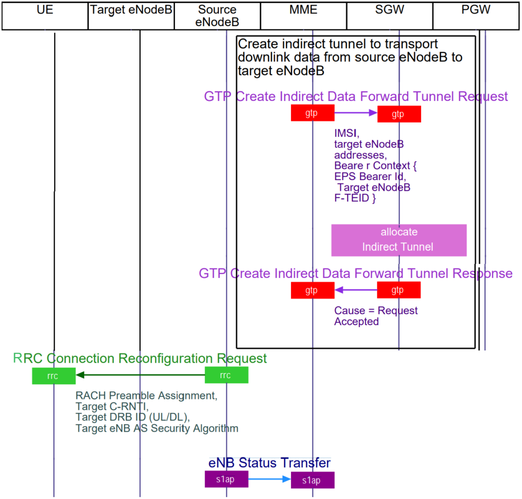
Upon receiving the handover command, the UE adjusts its connections accordingly, removing any bearers associated with the old cell that aren’t supported by the new target cell. This step ensures that the UE transitions smoothly to the new network cell without unnecessary data traffic.
Simultaneously, the source eNodeB informs the target eNodeB about the status of ongoing data sessions through an “eNodeB Status Transfer” message, facilitated by the MME. This message is critical as it conveys the current state of Packet Data Convergence Protocol (PDCP) and Hyper Frame Number (HFN) for specific data bearers where maintaining continuity is essential.
As the UE physically moves out of the source eNodeB’s coverage area and into the target eNodeB’s, the source eNodeB sends an “S1AP eNB Status Transfer” message to the MME. This message indicates the last sequence numbers of data packets sent and received by the source eNodeB in both uplink (from UE to network) and downlink (from network to UE) directions. This information helps the target eNodeB resume data transmission seamlessly from where the source eNodeB left off, ensuring uninterrupted service for the UE.
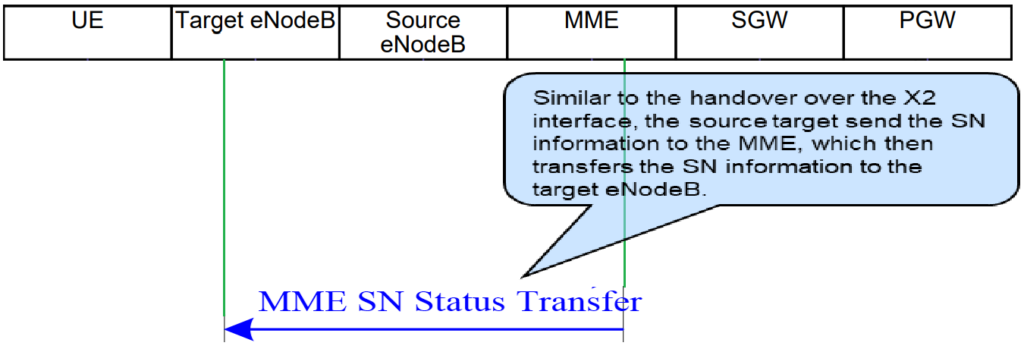
Step 6: S1AP MME Status Transfer.
The S1AP MME Status Transfer message forwards PDCP Sequence Numbers received from the source eNodeB to the target eNodeB. This ensures continuity in data transmission during a handover in LTE networks.
Step 7: S1AP Handover Notification.
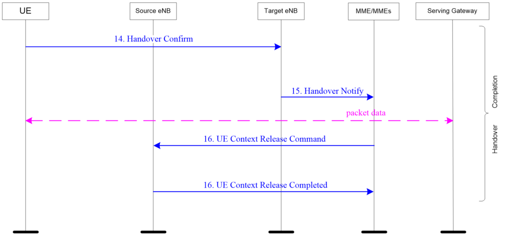
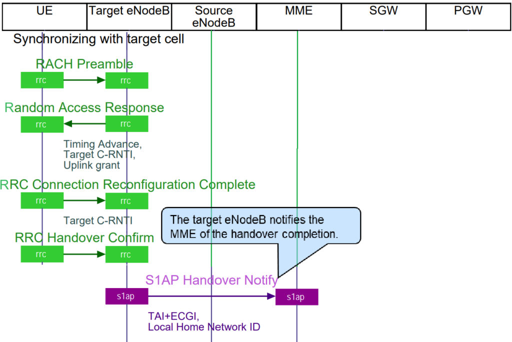
Once the UE completes the random access procedure and establishes a new RRC (Radio Resource Control) connection in the target cell, the target eNodeB sends an “S1AP Handover Notification” message to the MME. This message signifies the successful completion of the handover process.
Key points of the handover notification message include:
- Handover Completion: The message indicates that the handover from the source eNodeB to the target eNodeB has been successfully completed. It confirms that the UE’s radio and transport resources in the source eNodeB can now be released.
- E-UTRAN Cell Global Identity (CGI): It includes the identity of the new serving cell in terms of its Cell Global Identity (CGI). This uniquely identifies the new cell within the LTE network.
- Tracking Area Update: If the handover resulted in a change of the serving Tracking Area (TA), the UE may need to perform a tracking area update procedure. This procedure ensures that the Tracking Area Identity (TAI) is aligned between the UE and the MME’s NAS (Non-Access Stratum) protocol entities.
Step 8: GTP-C Modify Bearer Request.
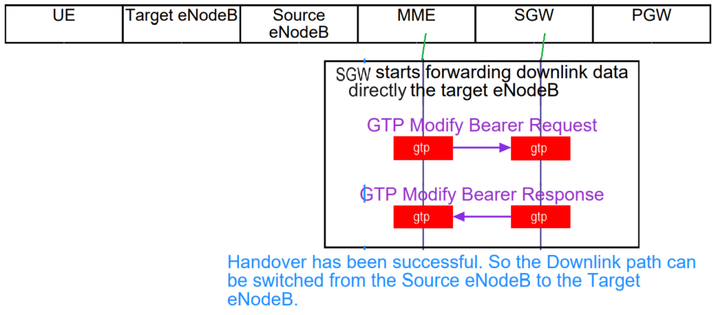
Once the handover process in LTE networks is completed, the MME (Mobility Management Entity) initiates the necessary adjustments to the S1-U GTP tunnel. Here’s how it happens:
- Tunnel Endpoint Adjustment: The primary task is to update the Downlink (DL) tunnel endpoint from the source eNodeB to the target eNodeB in the S1-U GTP tunnel. The Uplink (UL) tunnel endpoint at the Serving Gateway (S-GW) typically remains unchanged.
- GTP-C Modify Bearer Request: To accomplish this, the MME sends a “GTP-C Modify Bearer Request” message to the S-GW, as depicted in Message Example 2.29.
- Message Content: This message includes:
- EBI (EPS Bearer Identity): Identifies the specific bearer that needs modification.
- eNB F-TEID: Specifies the new DL tunnel endpoint, which is the Forwarding Tunnel Endpoint Identifier associated with the target eNodeB.
Step 9: GTP-C Modify Bearer Response.
After receiving the GTP-C Modify Bearer Request from the MME, the Serving Gateway (S-GW) in LTE networks responds with a GTP-C Modify Bearer Response message (Message Example 2.30). Here’s what happens next:
- Response Confirmation: The GTP-C Modify Bearer Response message confirms that the S-GW has successfully updated its configuration.
- Information Sent: This message includes the S1 SGW F-TEID (S1 Serving Gateway Forwarding Tunnel Endpoint Identifier) back to the MME.
- Endpoint Renegotiation: With both tunnel endpoints (DL at the eNodeB and UL at the S-GW) successfully renegotiated, the network is now ready to resume payload transfer.
- Payload Transfer: Following this exchange, data transfer between the UE and the network can proceed smoothly through the updated network configuration.
Step 10: S1AP UE Context Release Command due to “Successful Handover”.
After a successful handover in LTE networks, the MME (Mobility Management Entity) takes the final steps to release the resources that were used during the handover process.

Here’s how it happens:
- Resource Release Trigger: The MME initiates the release of transport and radio resources that were allocated for the outgoing leg of the handover. These resources were previously used to maintain connectivity for the UE before it transitioned to the target cell.
- S1AP UE Context Release Command: To release these resources, the MME sends an “S1AP UE Context Release Command” message. This message includes a cause value indicating “Successful Handover,”.
- Purpose: The purpose of this command is to inform the old eNodeB that the handover has been successfully completed and that it can now release all resources associated with the UE’s connection in the source cell.
- Confirmation: Upon receiving the UE Context Release Command, the old eNodeB responds with a “Successful Outcome” message (procedure code = “UE Context Release”). This confirms that all resources have been released successfully.
Full Course on LTE RF Optimization (Explained by telecommunication industry experts).