When a User Equipment (UE) needs to switch between cells that belong to different eNodeBs over two different X2 links, an inter-eNodeB handover is triggered via the X2 interface. Initially, the UE reports event A3 or A4 measurements to the source eNodeB. Based on these measurements, the source eNodeB decides to initiate a handover. The source eNodeB then applies for resources from the target eNodeB over the X2 interface, ensuring that the necessary preparations are made in the target cell.
Upon successful resource preparation, the source eNodeB sends a reconfiguration message to the UE, instructing it to move to the target cell. After the UE successfully connects to the target cell, the target eNodeB informs the source eNodeB to release the radio resources of the source cell. This step includes the transfer of any non-transmitted data from the source eNodeB to the target eNodeB, ensuring that no data is lost during the transition. Additionally, the source eNodeB updates the user and control plane relationships to reflect the new connection.
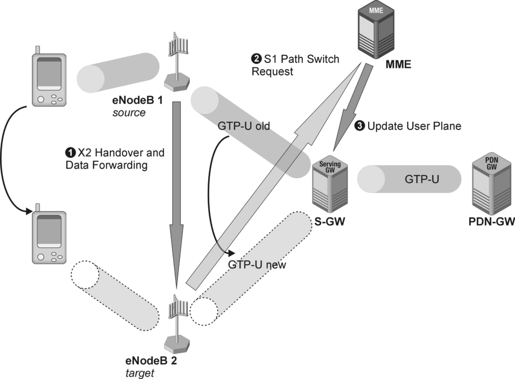
The X2 handover process consists of three major steps.
First, the X2 handover preparation procedure establishes a signaling connection using the X2 Application Part (X2AP) and creates a temporary user plane tunnel to forward any unsent data from the source eNodeB to the target eNodeB. This step ensures that the target eNodeB is ready to receive the UE and handle its data traffic.
Second, the target eNodeB uses the S1AP path switch request procedure to inform the Mobility Management Entity (MME) of the UE’s new location. The target eNodeB requests a new route for the GTP-U tunnel on the S1-U interface, which is crucial for maintaining the data flow to and from the UE.
Third, the MME then communicates with the Serving Gateway (S-GW) to set up the new endpoints for the GTP-U tunnel, enabling the new route for user plane data.
After the handover, the UE performs a tracking area update to inform the network of its new location. This update ensures accurate tracking and appropriate routing of data and signaling messages, maintaining seamless service and quality of connection.
LTE X2 Handover Procedure & Signaling.
Below pictures represents complete signaling of LTE X2 handover and its procedure. In later sections, I explained step by step each stage of LTE signalling of X2 handover.
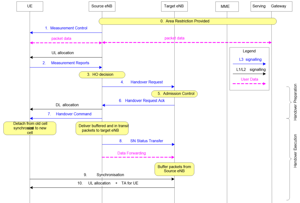
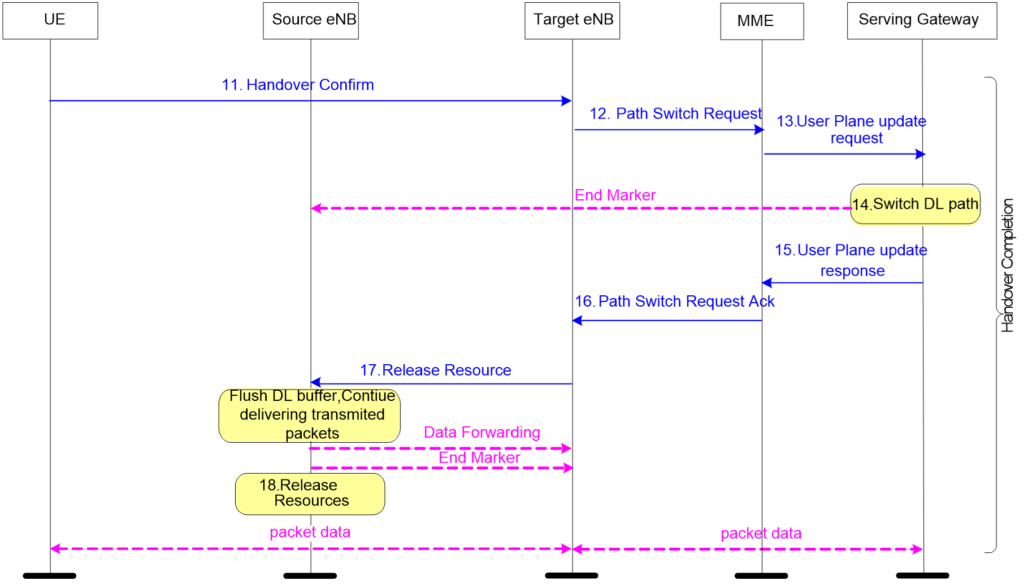
Step 1: X2AP Handover Request.
The X2 handover procedure is initiated by the source eNodeB when triggered by a downlink (DL) or uplink (UL) quality measurement result. The source eNodeB sends an X2AP Handover Request to the target eNodeB.
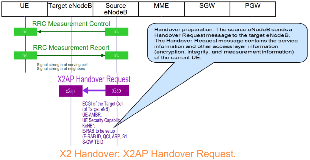
This message, essential for handover preparation, includes several key elements:
- Cause Value: Indicates the reason for the handover, typically “handover desirable for radio reasons.”
- Cell-ID: Identifies the source cell.
- GUMMEI: Identifies the MME managing the mobility procedures for the specific call.
- MME-UE-S1AP-ID: The unique identifier for the call within the MME S1AP protocol entity.
- e-RAB-ID and QoS Parameters: Lists active e-RABs for the radio connection, including their QoS parameters.
- UL TEID: The currently assigned UL TEID by the S-GW for the IP tunnel on the S1-U interface.
- RRC Context: Includes security parameters and other essential information for the radio connection.
- Access Stratum Security Information: Contains security keys like key-eNB.
These elements ensure that the target eNodeB has all necessary information to prepare for the incoming UE, maintaining seamless connectivity and service quality during the handover process.
Step 2: X2AP Handover Request Acknowledge.
After receiving the X2AP Handover Request from the source eNodeB, the target eNodeB responds with an X2AP Handover Request Acknowledge. This acknowledgment message confirms successful handover preparation and includes several critical elements:
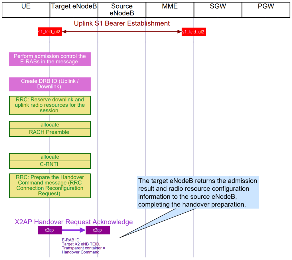
- e-RAB-ID(s): The same identifiers for the radio bearers that were found in the initiating message.
- UL TEID and DL TEID: Unique identifiers for the uplink and downlink tunnels, assigned by the target eNodeB. These TEIDs are used to forward any unsent payload packets from the source eNodeB to the target eNodeB via the X2 interface.
- Transport Layer Address: The network element’s address that will handle the packet forwarding.
The TEIDs are used to establish a temporary GTP-U tunnel on the X2 reference point, which is a unidirectional connection for forwarding packets still stored in the source eNodeB’s buffer. This tunnel operates without acknowledgment from the receiver, relying on higher user plane layers like TCP to handle any necessary retransmissions in case of packet loss.
The assignment of separate TEIDs for UL and DL by the target eNodeB helps to distinguish between UL traffic needing to be sent to the S-GW and DL traffic needing to be sent to the UE. Additionally, the message includes a transparent container with radio resources and scheduling information initially assigned by the target cell for this specific radio connection. This ensures that the target eNodeB is prepared to serve the incoming UE effectively, maintaining service continuity and quality during the handover.
Step 3: X2AP SN Status Transfer.
During the handover process, the source eNodeB initiates the “SN Status Transfer” by sending an X2AP message to the target eNodeB.
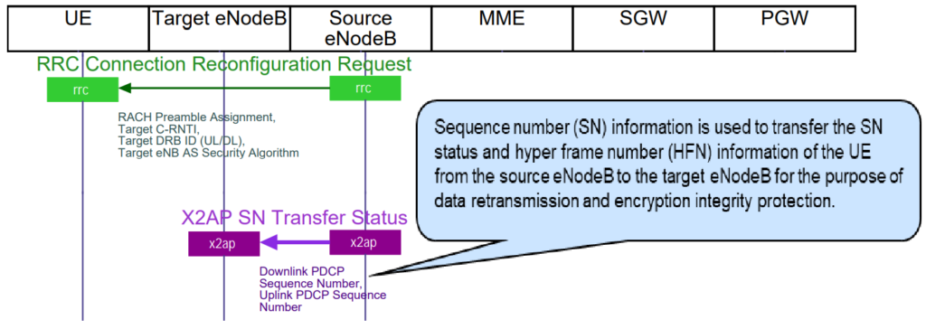
This message includes:
- e-RAB-ID(s): Identifiers for the radio bearers affected by the handover.
- PDCP SNs: Packet Data Convergence Protocol Sequence Numbers for both uplink (UL) and downlink (DL) data transfers across the radio interface.
These PDCP SN count values are crucial for ensuring a seamless continuation of ciphering and integrity protection functions post-handover. By transferring the current state of the sequence numbers (SN), the target eNodeB can maintain data integrity and security without interruption, ensuring that the user’s ongoing data sessions continue smoothly after the handover.
Step 4: S1AP Path Switch Request.
To switch the S1-U GTP tunnel to the target eNodeB, the target eNodeB sends a Path Switch Request to the MME.
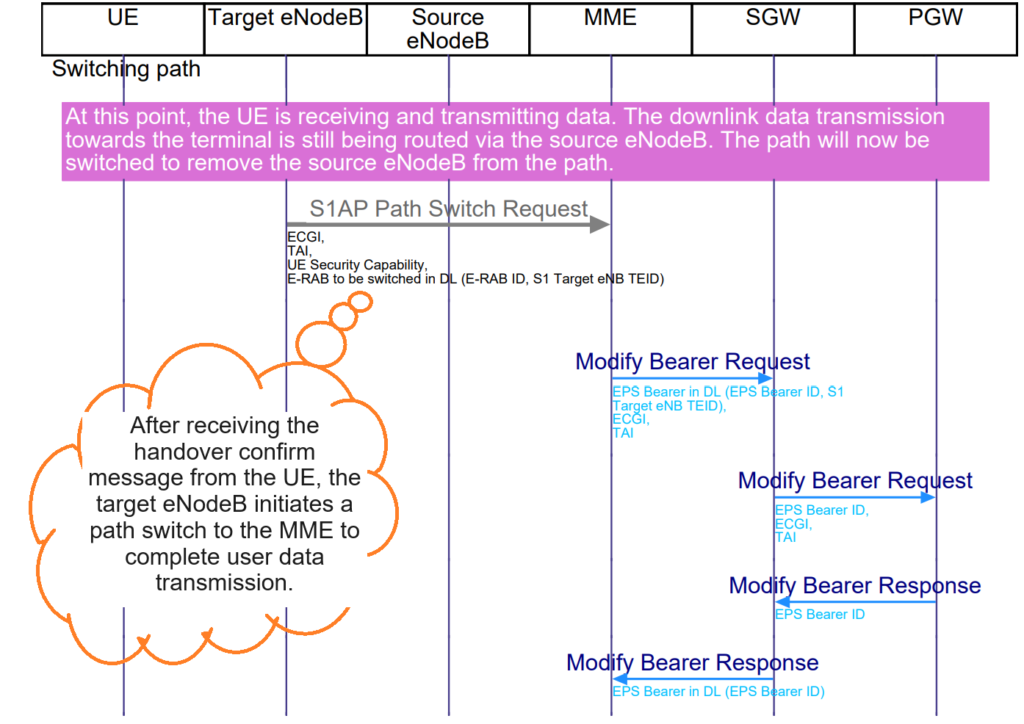
This message includes:
- Target Cell ID and TAC: Represents the new location of the UE.
- SourceMMEUE-S1AP-ID: Identifies the specific connection within the MME’s S1AP entity.
- DL GTP-U TEID: The identifier for sending payload packets in the downlink direction on the S1-U interface after the path switch.
- E-RAB ID(s): Identifies the E-RAB(s) to be transported in the new GTP-U tunnel.
This message ensures that the payload packets are routed correctly to the new eNodeB, maintaining seamless data flow during and after the handover process.
Step 5: GTP-C Update Bearer Request.
To switch the GTP-U tunnel on the interface between the eNodeB and the S-GW, the MME sends a GTP-C Update Bearer Request to the S-GW.

This message includes:
- EBIs of the RABs: Identifies the bearers to be switched.
- S1-U eNB TEID: The identifier for downlink payload transmission using the new tunnel, as provided by the target eNodeB.
This step ensures that the S-GW updates its routing information to forward data correctly to the target eNodeB, maintaining the integrity and continuity of the user data session during the handover process.
Step 6: S1AP Path Switch Acknowledge.
After updating the user’s connection during a handover in LTE, the MME sends a message to the new base station (eNB). This message, known as the S1AP Path Switch Acknowledge, tells the new base station that the uplink data transfer identifier (TEID) will stay unchanged on the connection between the mobile device and the network. This confirmation ensures that data continues to flow smoothly without interruption.
Step 7: X2AP UE Context Release.
After a successful handover and path switch on the radio interface in LTE networks, the target eNB sends an X2AP UE Context Release request to the source eNB. This message confirms that the handover has been completed successfully.
In this message:
- The specific UE (User Equipment) connection is identified by two IDs: Old-eNB-UE-X2AP-ID and New-eNB-UE-X2AP-ID.
- Upon receiving this request, the source eNB releases all the UE-specific information and radio resources associated with that particular UE.
- However, it may continue forwarding user plane data to the target eNB as needed, ensuring continuity of service for the user without interruption during the handover process.
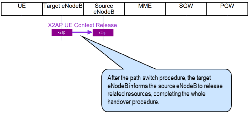
The end marker has been received at the Target eNodeB. At this point the target asks the source eNodeB to release resources for the UE.
After a successful handover between different cells in LTE, the UE needs to update its location information on the NAS (Non-Access Stratum) layer, especially if the target cell belongs to a different tracking area (TAC) than the source cell.
Step 8: Tracking Area Update Request.
- Detection of Target Cell: The UE detects the new cell’s broadcast information, including the TAC of the target cell.
- NAS Message Sent: The UE sends a NAS Tracking Area Update Request to the MME via the target eNB using the S1AP UL NAS transport message.
- Information Included: This message contains:
- New location of the UE (cell ID of the target cell) and the new TAC.
- Old GUTI (Globally Unique Temporary Identifier) to identify the UE on the NAS layer.
- UE network capabilities and TAC of the old (source) cell.
Step 9: Tracking Area Update Accept.
- MME Response: Upon receiving the Tracking Area Update Request, the MME responds with a NAS Tracking Area Update Accept message to the UE.
- New GUTI Assignment: Depending on the MME’s configuration, a new GUTI might be assigned and included in this message.
- Confirmation: The UE acknowledges the reception of the new GUTI with a TAC (Temporary Authentication Command) message.
This process ensures that the UE’s location information is updated in the network’s core system, facilitating seamless mobility management and maintaining uninterrupted services for the user during cell transitions.
Full Course on LTE RF Optimization (Explained by telecommunication industry experts).