- SCOPE
- REFERENCES
- GENERAL
- SAFETY
- SELECTION OF PROCESS
- EXECUTION
- Joint Preparation
- Preheating
- Cooling
- Welding Technique
- OXYACETYLENE WELDING (FGW)
- SHIELDED METAL ARC WELDING (SMAW)
- Nickel or Nickel-Base Electrodes
- Mild Steel and Specially Coated Steel Electrodes
- Copper Base Electrodes
- OXYACETYLENE BRAZING
FIGURE
- Joint Preparation
- Typical Preheat Furnace
Guide for Repairs of Cast Iron by Welding or Brazing
1. Scope
This article is a guide for making necessary repairs to cast iron using the Shielded Metal Arc Welding (SMAW), oxyacetylene welding (FWG), or brazing processes.
2. References
Reference is made in this standard to the following documents.
American Society of Mechanical Engineers (ASME)
Section VIII Rules for Construction of Pressure Vessels
American Welding Society (AWS)
A 5.1 Specification for Carbon Steel Covered Arc-Welding Electrodes A 5.6 Specification for Copper and Copper-Alloy Covered Electrodes A 5.15 Specification for Welding Electrodes for Cast Iron
A 5.27 Specification for Copper and Copper-Alloy Rods for Oxyfuel Gas Welding
3. General
3.1 Repair of cast iron by welding or brazing shall be done when it is absolutely necessary. Where possible, mechanical repair methods shall be used, since welding or brazing provide no greater than a 50 percent chance of success.
3.2 The following types of cast iron are addressed in this standard for repairs of cast iron by welding or brazing. Alloy cast irons (white and chilled) cannot be welded or brazed.
-
- Gray.
- Nodular (ductile) iron.
- Malleable iron.
3.3 The repair of cracks or other defects in cast iron is difficult because of the high degree of welding skill needed, and the time-consuming and extremely critical preheat and postheat procedures necessary to minimize or avoid heat-affected zone (HAZ) cracking.
3.4 ASME Section VIII, UCI-78 provides permits limited approval to repairing pressure vessels constructed of cast iron. ASME Section VIII, UCD-78 does not permit cast ductile iron welding for repairs.
4. Safety
Safe practices prescribed in SES W02-F01 shall be followed on plant sites.
5. Selection of Process
Process selection is determined by the physical strength required, cost, corrosion resistance of the deposit, machinability, and color match. Attention shall be given to possible galvanic action. The most reliable method utilizes oxyacetylene welding with cast iron welding rods. Where galvanic action is not a problem, oxyacetylene brazing may be employed. Where extensive heating is impractical or undesirable, arc welding procedures shall be utilized. However, users are cautioned against being optimistic regarding the success of arc-welded repairs. Gas welding and gas brazing are considered obsolete methods except for repairing small castings. Refer to SES W01-F02 and W03-F02 for guidance in selecting the proper welding or brazing process.
6. Execution
6.1 Joint Preparation
6.1.1 In preparing a casting for repair by welding, all cavities and cracks shall be opened up and cleaned of sand or other undesirable materials. Chipping, sawing, machining, arc gouging, or grinding shall be used in repair preparation. Magnetic particle inspection is preferred to ensure that a defect has been completely removed.
6.1.2 Oil and grease tend to penetrate the porous structure of iron castings and shall be removed. Heat the casting to 316 °C (600 °F) to expel oil and grease.
6.1.3 Prepare joints to be welded by V grooving. Single V grooves are desirable for thin sections or joints that are accessible from only one side. Thicker sections, wherever practical, shall have joints prepared by grooving both sides. For oxyacetylene welding, grooves with included angles of 60 degrees are desirable; and this angle shall be increased to as much as 90 degrees for thicknesses of 25.4 mm (1 in) or more. SMAW requires a V groove with an included angle of at least 60 degrees. Illustrated on Figure 1 are the joints described.
Figure 1 – Joint Preparation

6.2 Preheating
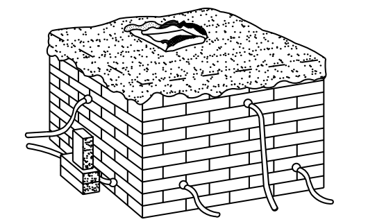
6.2.1 Castings shall be carefully preheated to avoid high thermal stresses which cause cracking. Much depends upon the size and shape of the casting. The preferred method is to construct a furnace of firebrick (laid dry) to surround the casting and cover the top with an insulating material. Enough burners shall be provided to heat the casting evenly. Figure 2 shows a typical preheat furnace.
Figure 2 – Typical Preheat Furnace
6.2.2 Use simple hand torches where little preheating is required, or if the casting is small and of suitable shape. In many cases, because of the shape of the casting, localized preheating is sufficient.
6.2.3 A contact pyrometer or Tempilstik temperature indicating crayon can be utilized to facilitate heat control.
6.3 Cooling
When furnace heating is employed, the cooling of the casting shall be controlled by burner adjustment with careful attention to temperature decline. When using hand torch heating, the casting shall be cooled by gradual withdrawal of the torch. Sometimes cooling can be controlled well enough by covering the casting with insulation, ashes or sand. Drafts shall be avoided.
6.4 Welding Technique
The general rule is to weld from points of greatest restraint to points of minimum restraint. Proper welding sequence, peening, and skipping, with arc welding electrodes, will speed up the operation by allowing particular beads to cool before proceeding with the next pass.
7. Oxyacetylene Welding (FGW)
7.1 Oxyacetylene welding shall be used on cast iron whenever machining is required after welding, or color match between weld and base metal is required. This method offers the best probability of success. Successful gas welding results when sharp thermal gradients between weld and casting are eliminated. The entire casting shall be preheated uniformly to a temperature of at least 538 °C (1000 °F) and cooled slowly after welding [not over 93 °C (200 °F) per hour]. Small castings can be heated with torches or by induction. Large castings require a furnace, either temporarily gas-fired or charcoal-heated, or the use of a permanent type gas or electric furnace with open top to allow welding while casting is in the furnace.
7.2 Filler metals shall conform to AWS A 5.15 as follows:
-
- Gray Cast Iron to RCI.
- Alloy Cast Iron to RCI-A.
- Nodular Cast Iron to RCI-B.
7.3 Fluxing is essential in FGW of cast iron to break down the oxide film. Flux shall be as recommended by filler metal manufacturer.
7.4 Unless the casting is small and preheated by the welding torch during the welding operation, a furnace shall be provided to obtain uniform heating of the entire casting. Adequate preheat results in stress relief, prevents gas pockets, and allows for better cooling conditions after welding.
a. Depending upon the size and shape of the casting, preheating furnaces can be efficiently built of bricks and covered with insulation to conserve heat and protect the operators. Gas-Fired torches or charcoal can be used as the source of heat. The main consideration is to prevent sudden heating, particularly when the casting contains widely varying metal thicknesses.
b. Preheating shall be to a minimum of 538 °C (1000 °F). Monitoring of this temperature can be accomplished as indicated in 6.2.3. Excessive preheat temperatures can result in warping of the casting due to its own weight. The best practice is to perform the welding while the casting is still in the furnace. This can be accomplished by positioning the casting so that the top of the furnace can be removed to expose the location of the repair.
7.5 A 60 to 90 degree V angle is required for gas welding. The edges shall be prepared by chipping, sawing, machining, arc gouging, or grinding.
a. A neutral concentrated flame shall be used with a high-velocity tip about 3.2-6.4 mm (1/8-1/4 in) from the metal surface. The bottom of V shall be melted by playing the flame from side-to-side. The welding rod tip shall be heated and dipped in flux. The joint shall be progressively fluxed by adding flux from the rod. Backhand or forehand technique may be used. Filler rod shall be added by actually rubbing the rod into the melted puddle. Care shall be taken to maintain fusion between the sides of V and the filler rod and to prevent the pool from running ahead on unmelted base meta The technique shall melt conditions as in any other type of fusion welding. One of the most important considerations is to obtain fusion between filler and base metal. The technique of welding cast iron shall be such that, as the weld progresses, oxides and impurities are floated to the surface to avoid porosity in the weld.
b. Flux shall be added regularly and allowed to float to the top of the weld puddle. Whenever gas bubbles or white spots appear on the puddle, flux shall be added in order that these impurities may float out.
c. The weld layer depth shall not exceed 9.5 mm (3/8 in).
7.6 When the welding has been completed, the casting shall be cooled slowly. If it is small and in a furnace, the opening through which the welding was done shall be covered and the furnace allowed to cool in still air.
a. When it is desired to stress relieve the casting, it shall be thoroughly heated to 621 °C (1150 °F) and held for approximately one hour for each 25.4 mm (1 in) of thickness and allowed to cool at a rate not greater than 10° C (50 °F) per hour, until it reaches 371 °C (700 °F), then furnace cooled to room temperature.
8. Shielded Metal Arc Welding (SMAW)
8.1 Nickel or Nickel-Base Electrodes
8.1.1 These electrodes are used in repairing surface defects or for joining thin or moderately thick sections. The process is quick and applicable to repair in any welding position. Downhand welding is easiest. The welds are machinable. Heavy sections of cast iron are more susceptible to cracking during shielded metal arc welding than with the oxyacetylene welding or brazing processes.
8.1.2 Filler metals shall conform to AWS A 5.15 as follows:
-
- Gray Cast Iron to ENi-CI.
- Nodular Cast Iron to ENiFe-CI.
- Alloy Cast Iron to ENiCu-A.
8.1.3 Preheating of cast iron shall be as per 9.5.
8.1.4 Cooling in air shall be satisfactory. Quenching with water is not possible.
8.1.5 Small electrodes, short arc, and low welding currents shall be required. The weld shall be deposited as stringer beads in increments of 50.8 mm (2 in). The welding sequence shall be worked so that minimum stresses will be built up. The slag shall be removed from each pass. At least two layers shall be deposited to take advantage of the annealing effect. Alloying of the weld deposit with the base metal will be minimized by limiting the penetration. To forestall avoidable shrinkage stresses in the cooling stage, the casting shall be kept cool as welding progresses.Manufacturer’s recommendations shall be followed for welding current values. Excessive porosity sometimes is encountered in the first bead; if this occurs, the entire bead shall be chipped or ground out and rewelded.
8.2 Mild Steel and Specially Coated Steel Electrodes
8.2.1 Procedures shall be employed that utilize mild steel electrodes only for repairing pits and small cracks.
8.2.2 It is virtually impossible with this type of welding to prevent the formation of a hard layer at the fusion zone. The process is unsuitable for machinable welds. High stresses develop as the weld deposit cools because the shrinkage of steel is greater than that of cast iron. This uneven shrinkage frequently causes cracking.
8.2.3 Filler metals shall conform to AWS A 5.1 and A 5.15 as follows:
-
- Low Melting Point to ESt, Mild Carbon Steel to E6010, E6011, E6012, or E6013.
8.2.4 Preheat only when necessary to prevent excessive stresses in other parts of casting.
8.2.5 As welding progresses, casting shall be kept cool.
8.2.6 In order to distribute the heat, short and widely separated stringer beads shall be deposited. Each bead shall be lightly peened. Slag shall be removed from each bead before depositing the subsequent beads. Manufacturer’s recommendations shall be followed for current values.
8.2.7 Cleaning – If repaired area is to be painted, all slag shall be completely removed.
8.3 Copper Base Electrodes
8.3.1 Procedures that utilize copper-base electrodes are similar to those described for nickel electrodes. These procedures shall not be used where machinability and color matching are important, or where galvanic action is a factor.
8.3.2 Filler metals shall conform to AWS A 5.6, A 5.15 as follows:
-
- Aluminum Bronze to ECuAl – A2.
- Phosphor Bronze to ECuSn – C.
- Phosphor Bronze to ECuSn – A.
8.3.3 Preheating of casting is not required.
8.3.4 The weld shall be made by depositing stringer beads in short increments, widely separated. Each bead shall be lightly peened. Manufacturer’s recommendations shall be followed for current values.
8.3.5 As welding progresses, casting shall be kept cool.
9. Oxyacetylene Brazing
9.1 Oxyacetylene brazing can be used on cast iron for obtaining strong and tight joints. Normally, dismantling of parts is not necessary when brazing. If the casting is subject to electrolytic corrosion, or color matching between the joint and casting is required, brazing cannot be used. Brazing shall not be employed if the casting is to be used in service in excess of 260 °C (500 °F), due to the low strength of the joint beyond that temperature.
9.2 Filler metal shall conform to AWS A 5.27 as follows:
-
- Copper-Zinc to RCuZn.
- Naval Brass to RBCuZn-A.
- Nickel Brass to RBCuZn-D.
9.3 Flux shall be as recommended by manufacturer of filler metal.
9.4 A slightly oxidizing oxyacetylene flame shall be maintained in order to preserve a thin oxide film on the pool of molten metal, which will prevent excessive zinc fuming. The working area shall be well ventilated as a protection against zinc fumes. The oxidizing flame serves to burn off the graphite on the prepared surfaces of the cast iron, which is essential for proper bonding.
9.5 If the sections of the casting vary widely in thickness, the entire casting shall be preheated to about 371 °C (700 °F), either in a charcoal-fired temporary furnace or by large gas torches kept constantly in motion. If preheating of the entire casting is not practical, local torch preheating may be adequate.
9.6 A 60 to 90 degree V angle is desirable for brazing. The surfaces shall be clean. This may require sandblasting. The V and adjacent area at the start are heated to dull red. The filler wire is warmed in the flame, dipped in flux, and melted into V. Tinning or sweating onto the surface will occur when the casting is at the correct temperature. If too cold, the molten metal will ball up or run off. If too hot, it will boil and form small globules which will not tin the surface. If flux-coated rods are used, addition of extra flux may be needed. Brazing can proceed as rapidly as the tinning occurs. Complete layers about 6.4 mm (1/4 in) deep for the length of the repair. Attention shall be paid to tinning ahead, so that the molten metal will not run onto cold metal. A slight incline of the part may be advantageous so that braze welding is done uphill.
9.7 Immediately after brazing, the casting shall be covered with insulation and allowed to cool slowly.