Following topics to be discussed in this article are
- SCOPE
- REFERENCES
- GENERAL
- SAFETY
- MATERIALS
5.1 Welding Electrodes
- WORKMANSHIP
6.1 Preparation of Joint
6.2 Welding Technique and Fit-up
6.3 Shield Metal Arc Welding (SMAW)
6.4 Oxyacetylene Braze Welding
6.5 Gas Tungsten Arc and Braze Welding
6.6 Gas Metal Arc and Braze Welding
6.7 Coating of Welds and Damaged Galvanized Surfaces
- INSPECTION
FIGURE
- Horizontal Rolled and Horizontal Fixed Positions
- Vertical Fixed Position
- Fillet Welds
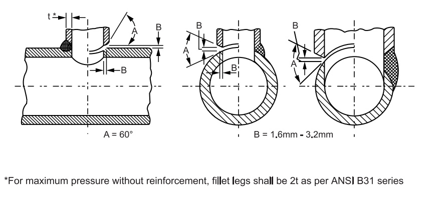
- Details of Nozzles and 90 Degree Branches
Welding and Braze Welding Galvanized Steel
1. Scope
This article provides suitable information for fabricating weldments of galvanized steel.
2. References
Reference is made in this standard to the following documents.
American National Standards Institute (ANSI)
B31 Piping Series
American Welding Society (AWS)
A 5.7 Specification for Copper and Copper Alloy Bare Welding Rods and Electrodes
A 5.8 Specification for Brazing Filler Metals
3. General
3.1 Butt and fillet welds are described in this standard.
3.2 Flat, vertical, horizontal, and overhead positions are described in this standard.
3.3 For shielded metal arc welding (SMAW) using direct current reverse polarity or alternating current, see SES W05-F01.
3.4 For oxyacetylene braze welding, see SES W04-F01.
3.5 For gas tungsten arc welding (GTAW), see SES W07-F01
3.6 For weldments of sheet metal, see SES W06-F19.
3.7 All welding and tack welding shall be done by welders who have satisfactorily passed welder’s qualification tests.
3.8 For guidance in the selection of the proper welding process see SES W01-F02 and W03-F02.
4. Safety
4.1 Adequate ventilation shall be provided during welding or cutting involving fluxes, coverings, or other materials which contain fluorine compounds, or involving zinc-bearing base or filler metals, or metals coated with zinc compounds. This is especially important when welding is to be performed in confined areas. Adequately ventilate areas adjacent to the welding operation to protect people. For information on exhaust ventilation, see SES W02-F03.
4.2 Safe practices prescribed in SES W02-F01 shall be followed on plant sites.
5. Materials
5.1 Welding Electrodes
Filler metals for galvanized steel shall be as per following standards: (i) SES W03-F01 (ii) SES W05-F02 (iii) SES W05-F03 (iv) SES W06-F02 (v) SES W07-F01
6. Workmanship
6.1 Preparation of Joint
6.1.1 General guidance for joint preparation is shown on Figures 1 to 4. For additional dimensional information on material thicknesses, see the tabulated data in SES W11-F01.
6.1.2 In configurations such as fillet welds between heavy sections, a reservoir of the molten zinc may become entrapped at the root of the weld which can result in cracking. Cracking is caused by intergranular penetration of liquid zinc into the resolidified weld metal and heat-affected zones in the base metal.
6.1.3 To prevent cracking which results from liquid-metal penetration (a) Remove zinc by grinding or other means from the area where melting occurs as shown on Figures 1, 2, and 3 (b) Use sufficient heat input and gap to secure full penetration of the joint and (c) Avoid restraint on the weld. If the galvanizing is removed, the weld pool flows more readily. This also facilitates welding, and thus fumes of the zinc is minimized.
6.2 Welding Technique and Fit-up
6.2.1 Joint configurations and fixtures which permit entrapment of volatilized zinc from the abutting edges and back side of the joint shall be avoided by providing a small gap between abutting edges of the weld or by using a grooved backing strip, or both. For example, fillet welds on T joints are best made when there is a gap between the two abutting members to allow entrapped zinc to escape via the root.
6.2.2 When a grooved copper backing strip is used, burn off from the zinc coating of the back side is minimized if the groove is only slightly wider than the gap between the abutting edges. Although the zinc melts on the back side, it resolidifies, thereby restoring some corrosion resistance to the base metal coating (although the weld root remains bare).
6.3 Shield Metal Arc Welding (SMAW)
SMAW shall conform to SES W05-F03 and W05-F02.
6.4 Oxyacetylene Braze Welding
6.4.1 The oxyacetylene torch is the heat source most commonly used for brazing. A neutral to slightly oxidizing flame is employed in conjunction with a filler rod of 60 Cu – 40 Zn alloy (RBCuZn – A) as specified in AWS A 5.8 to braze galvanized steel. This type of flame and filler (which melts just below the boiling point of the zinc coating) minimizes the loss of zinc.
6.4.2 A small torch tip and low heat consistent with the gage of material being brazed shall be used. The diameter of the filler rod shall be approximately 1 1/2 times the thickness of material being joined for sheet thicknesses of up to 4.8 mm (3/16 in). A 6.4 mm (1/4 in) diameter rod is usually used for thicknesses over this.
6.4.3 A generous quantity of brazing flux applied to the filler rod and the joint area reduces zinc loss and produces sound joints. The oxyacetylene flame shall be directed mainly on the filler to minimize heat input to the base metal. Proper temperature of base metal is indicated by a cherry red color. The forehand technique is usually preferred.
6.5 Gas Tungsten Arc and Braze Welding
6.5.1 A violent spattering of the zinc under the arc makes the process impractical in most cases. Contamination of the electrode and fouling of the gas cup leads to erratic arc behaviour and difficulty in producing sound deposits. Where it is necessary to fusion weld this material, and where it is impractical to remove the zinc, these difficulties can be minimized by (a) tilting the torch to blow vapor away from the arc (b) increasing the gas flow (c) keeping heat input low and (d) spraying the gas cup with a silicone antispatter compound to facilitate cleaning. Preparation of base metal and welding techniques for sheet, plate, and structural steel are the same as for welding ungalvanized steel. Techniques for avoiding entrapment of zinc, as discussed in sections 6.1 and 6.2 shall be employed. When welding pipe, galvanizing shall be removed by grinding on any surfaces where there is melting of the base metal.
6.5.2 Braze welding with silicon-bronze filler (ERCuSi – A), as specified in AWS A 5.7, is accomplished by using DCSP (Direct Current Straight Polarity) with sufficient amperage to provide melting of the filler and bonding of the resulting weld pool to the base metal. This process is successfully used on sheet metal. Joints have good strength. Loss of zinc adjacent to weld bead is minimal. The arc is directed into the weld pool, and manipulated along the line of the weld, adding filler metal and progressing at a rate of travel dictated by proper bonding of filler metal.
6.6 Gas Metal Arc and Braze Welding
6.6.1 CO2 or argon + CO2 mixtures are used for joining galvanized materials in GMAW. Common mild steel wires are used. Erratic arc characteristics and fouling of the gun nozzle are minimized by (a) spraying gun nozzle with anti-spatter compound, or (b) using a lead angle of 10 to 20 degrees. Best results are obtained when zinc is removed by grinding from surfaces where melting occurs. A rapidly disintegrating rock or flapper wheel removes the zinc instead of smearing it. If fusion welding is to be done without the removal of zinc, precautions outlined in 6.1 and 6.2 for avoiding entrapment of zinc shall be followed.
6.6.2 A method similar to braze welding is utilized wherein a silicon-bronze filler (ERCuSi – A ), as specified in AWS A 5.7 in combination with argon gas which provides excellent strength, at voltage and wire speed values sufficient to approximate short-circuiting transfer arc characteristics. A 20 to 30 degree lead angle is used, and speed is consistent with bonding of weld pool to base metal. The arc is directed into the weld pool rather than ‘leading’ the pool.
6.6.3 Welding guns incorporating fume removal nozzles are recommended.
6.7 Coating of Welds and Damaged Galvanized Surfaces
Welded or brazed joints shall be thoroughly wire brushed to remove slag, loose scale, and spatter. Where coated electrode welding has been done, such cleaning shall be followed by washing with potable water, then drying before applying paint. Apply two coats, each 50 microns (2 mil) dry-film thickness, of galvanized metal primer.
7. Inspection
7.1 The amount and type of inspection required depends upon the service conditions and hazards to personnel and property. It is the responsibility of the originator to define the inspection requirements. Inspection shall be in accordance with applicable code(s).
Figure 1 – Horizontal Rolled and Horizontal Fixed Positions
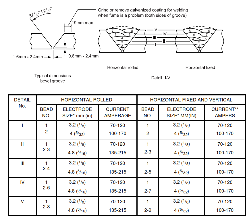
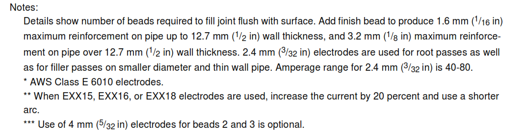
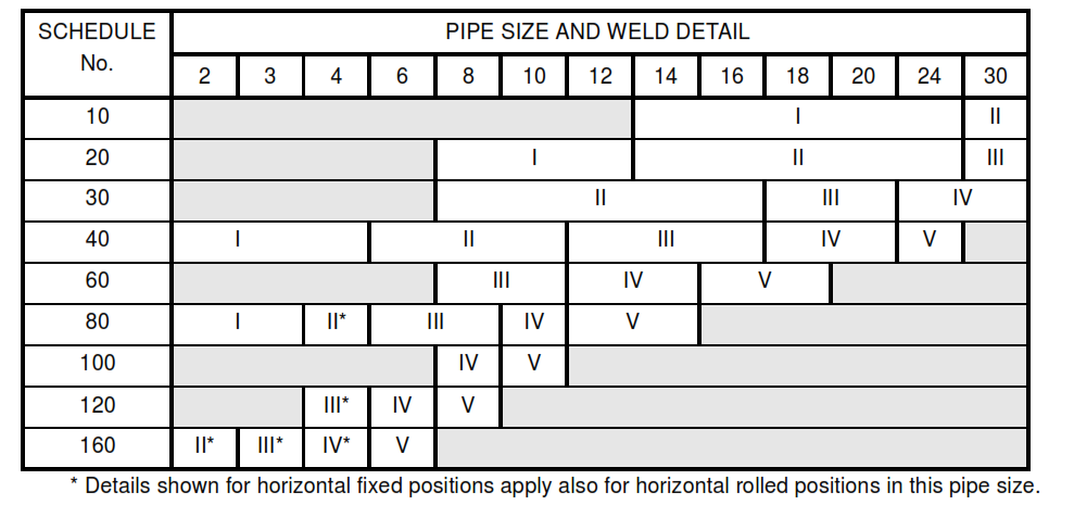
Figure 2 – Vertical Fixed Position
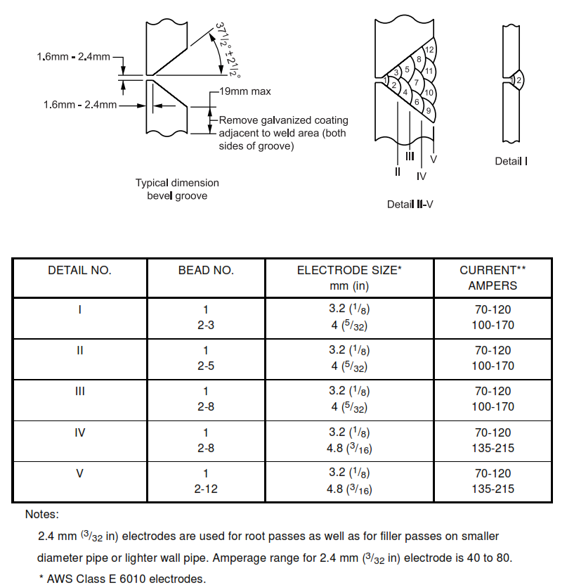

Figure 3 – Fillet Welds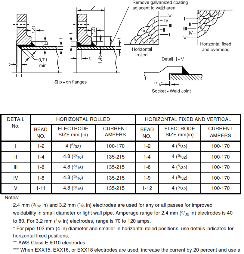
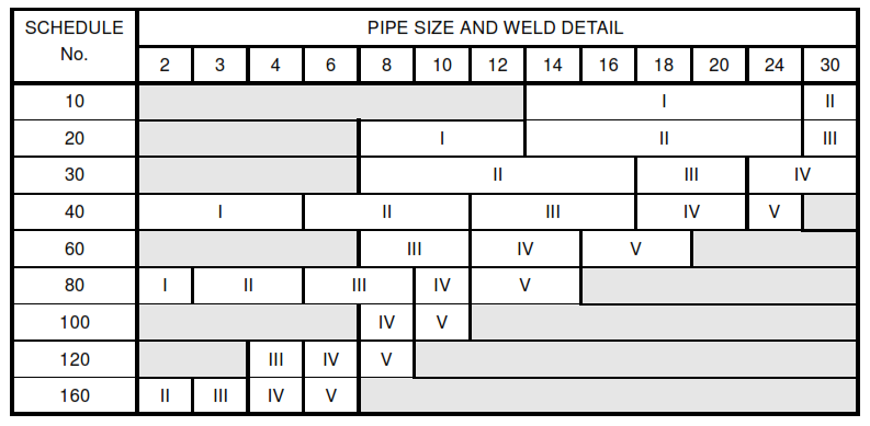
FIGURE 4 – Details of Nozzles and 90 Degree Branches