1. INSTALLATION MANUAL
1.1 Introduction.
1.2 Storage.
1.3 Foundation and Support Structure.
1.4 Installation Procedure.
1.5 Field Insulation.
2. OPERATION MANUAL
2.1 Introduction.
2.2 Commissioning.
2.3 Initial Start-up.
2.4 Normal Start-up.
2.5 Normal Operation.
2.6 Normal Shut-down.
2.7 Emergency Shut -down.
3. MAINTENANCE MANUAL
3.1 Introduction.
3.2 Routine Observation.
3.3 Inspection During Shut-down.
3.4 Cleaning.
1. INSTALLATION MANUAL
1.1 Introduction
This manual covers the installation procedure for one Opex Air Preheater. Following documents are to be used in conjunction with these procedures: Drawings are to be provided in the end of this article.
General Arrangement
Loading Diagram
Erection Drawing
1.2 Storage
The unit is delivered to site packed for transport and twelve months maximum storage at
site. It is recommended to cover the unit when stored at site, e.g. with tarpaulin
(waterproofed cover) or to place them in a space under cover, prior to field installation.
It is not necessary to unpack the materials prior to storage. Unpacking must be done only
prior to field installation.
1.3 Foundation and Support Structure
The unit is supported by a support structure.
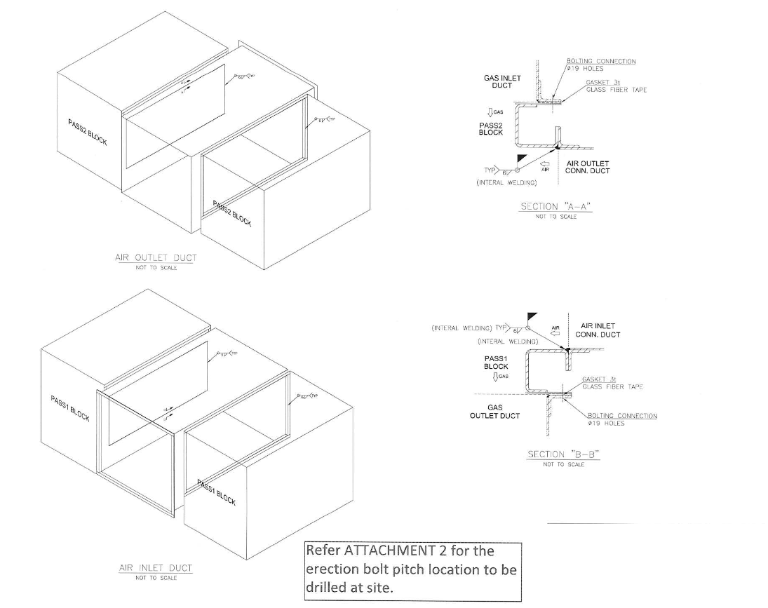
The fasteners and gaskets for support structure connections and duct work connections are provided by Shinhan apex.
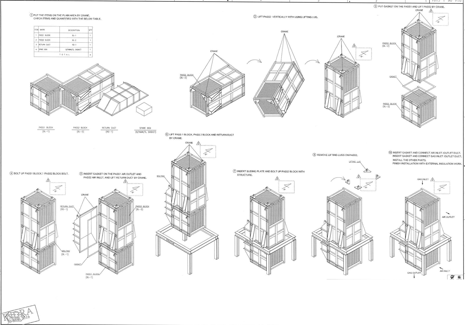
1.4 Installation Procedure
The shipping components must be unpacked prior to field erection.
Each shipping component becomes an erection component after unpacking.
The erection units can be lifted with conventional lifting equipment (cranes) suitable for the Weight and the dimensions indicated on drawings.
The unit is provided with permanent lifting lugs attached in the fabrication shop for transport, field handling and erection.
The detailed erection procedure is given below and included on Drawing No. P14-06-3 G101, P14-06-3-E101 Deviations from this procedure must be done with care, using sound engineering and erection practices.
If in doubt, please contact the manufacturer for advice.
Reference drawings are given below in the end of this article.
1.4.1 This installation outline
is meant as a reference only to assist the installation contractor, and does not relieve the installation contractor from his own installation work, or part thereof nor from normal practice. Installation contractor must pay the keen attention from damages and/or losses, regardless of what the cause thereof may be arising out of or connected during the installation.
1.4.2 After installation, and before start-up, it shall be carefully checked that all temporary structural bracing shall be removed, and pieces, lugs required for handling and lifting which are not necessary for ducting connection are removed
1.4.3 One module, 4 blocks, 2 return duct, 1 air inlet duct, 1 air outlet duct, for air preheater are transported to site separately.
1.4.4 Assembling.
Please refer to the drawing No. P14-06-1-G101, P14-06-1-E101
1.5 Field Insulation
Insulation material is applied in the field by others after completion of erection.
All external surfaces are provided with insulation nuts. The selection of insulation material,
lagging and specific insulation procedure is left to the party taking responsibility for field
insulation.
2. OPERATION MANUAL
2.1 Introduction
This manual covers the commissioning, start-up, normal operation and shut-down
procedures for one air preheater. Following documents are to be used in conjunction with
these procedures:
General Arrangement picture is given below.
2.2 Commissioning
Pre-commissioning must be performed prior to unit external thermal insulation.
During this operation all manholes in the air and flue gas duct work (provided with the
equipment or provide by others) must be open to allow internal inspection.
Pre-commissioning consists in checking the general external and internal condition of the
exchanger. The bolted flanges must be checked to ensure that all the bolts are installed
and tightened and gaskets are continuous and uniformly installed. The inside of the unit
must be inspected to ensure that all heat transfer blocks are in good condition, without
damage from transport or erection, and that all foreign materials, tools, etc. have been
removed.
It is recommended to close all manholes and/or sliding doors immediately after completion of the inspection and in any event before starting the application of external insulation.
In case commissioning is done shortly after pre-commissioning no additional inspection of
the unit is required, the pre-commissioning report being sufficient for unit initial start-up.
In case commissioning and initial start-up are delayed, it is recommended to repeat the internal inspection of the unit shortly before the initial start-up to ensure that no unusual
conditions (e.g. accumulation of rain water, dust, plugging of connections, etc.) developed during this period.
2.3 Initial Start-up
During the initial start-up it is recommended to increase the fluegas inlet temperature with
maximum 50°C per hour. The process variables (flows, pressures and temperatures) must
be closely monitored in order to detect any abnormal departure from the normal operating
conditions as early as possible. The unit must also be checked for vibration at part load as well as at full load.
2.4 Normal Start-up
No special precautions are required during the normal start-up of the unit.
It is recommended to increase the hot gas inlet temperature with maximum 50°C per hour.
The process variables (flows, pressures and temperatures) must be closely monitored at
regular intervals according to the normal start-up schedule.
2.5 Normal Operation
In normal operation the unit does not require any monitoring on a continuous basis.
The operating data must be recorded at regular intervals according to the normal plant
schedule. Field observation of the unit is also recommended at normal and regular
intervals, in conjunction with field observation of the complete heater. Any abnormal
operating conditions must be evaluated as early as possible.
2.6 Normal Shut-down
No special precautions are required during the normal shut-down of the unit.
It is recommended to reduce gradually the inlet hot gas temperature with maximum 50C
per hour.
The process variables (flows, pressures and temperatures) must be closely monitored at
regular intervals according to the normal shut-down schedule.
And It is recommended that the air fan is to be stopped after the gas temperature cools
down to the temperature required for other equipments, not to make the water condensate
in the air preheater
2.7 Emergency Shut-down
It is most probable that an emergency shut-down would occur relatively fast and would be
caused by other equipment or operating conditions, not necessarily related to the air
preheater.
Indeed, most abnormal conditions of the exchanger develop usually very
slowly and can be noticed long before the condition of the unit becomes totally
unacceptable from operation or safety point of view.
During an emergency shut-down the flue gas inlet temperature can drop suddenly, or the
air supply can stop suddenly. These conditions will not damage the exchanger, but their
occurrence must be avoided in order to prolong the life of the equipment.
The operator must check that during normal operation and particularly during an
emergency situation, the following limiting conditions are not exceeded:
-Max. flue gas inlet temperature: 350C
-Design. Pressure: 500 mm W.C.
In case 350°C and/or 500 mm W.C. limits have been exceeded for any length of time,
during normal operation or during emergency shut-down, it is recommended to consult the
equipment supplier in order to determine the suitability of the unit for continued operation,
with or without repairs.
3. MAINTENANCE MANUAL
3.1 Introduction
This manual covers the maintenance aspects for air preheater. Following documents are to be used in conjunction with these procedures;
Data Sheet No.:
P14-06-1-D111 Operating Data
P14-06-1-D121 Mechanical Data
General Arrangement is given below.
3.2 Routine Observation
The routine observation of the unit by operating personnel is described under point 2.5. Any abnormal condition which develops during operation must be discussed with maintenance personnel for planning of inspection and repair during the unit shut-down.
3.3 Inspection during Shut-down
It is recommended to inspect the unit through the manholes and sliding doors during the
normal shut- down periods, once in 12-18 months. During the inspection special attention
must be paid to the condition of the heat transfer surface. Fouling and corrosion aspects
must be carefully observed and addressed during the shut-down period or such actions
must be planned for future shut-down periods.
3.4 Cleaning
Elements must be inspected during normal shut-down. In case the heat transfer is fouled
the blocks must be washed with water from the top of the unit. The water washing will be
done using a temporary water jet.
It is recommended to clean elements with the water during each normal shut-down period.
In case the fouling conditions dictate water cleaning during operation, hot water at a
temperature of 80-90°C must be used in order to avoid thermal shocks.

Discover more from PAKTECHPOINT
Subscribe to get the latest posts sent to your email.