Reference Material form ASCE 7-95 Minimum Design Loads for Buildings and Other Structures.
ASCE 7-95 Minimum Design Loads for Buildings and Other Structures
FIGURE ASCE 7-95 – Multipliers for Obtaining Topographic Factor Kzt


3. Multipliers are based on the assumption that wind approaches the hill or escarpment along the direction of maximum slope.
4. Effect of wind speed-up shall not be required to be accounted for when H/Lh < 0.2 or when H < 15 ft (4.5 m) for Exposure D, or < 30 ft (9 m) for Exposure C, or < 60 ft (18 m) for all other exposures.
5. Notation:
H: Height of hill or escarpment relative to the upwind terrain, in feet (meters).
Lh : Distance upwind of crest to where the difference in ground elevation is half the height of hill or escarpment, in feet (meters).
K1 : Factor to account for shape of topographic feature and maximum speed-up effect.
K2: Factor to account for reduction in speed-up with distance upwind or downwind of crest.
K3 : Factor to account for reduction in speed-up with height above local terrain.
x: Distance (upwind or downwind) from the crest to the building site, in feet (meters).
z: Height above local.
FIGURE ASCE 7-95 – External Pressure Coefficients, GCp , for Loads on Building Components and Cladding for Enclosed or Partially Enclosed Buildings with Mean Roof Height, h, Less than or Equal to 60 ft (18 m).
FIGURE ASCE 7-95 Walls

Notes:
1. Vertical scale denotes GCp to be used with qh based on Exposure C.
2. Horizontal scale denotes effective wind area, in square feet (square meters).
3. Plus and minus signs signify pressures acting toward and away from the surfaces, respectively.
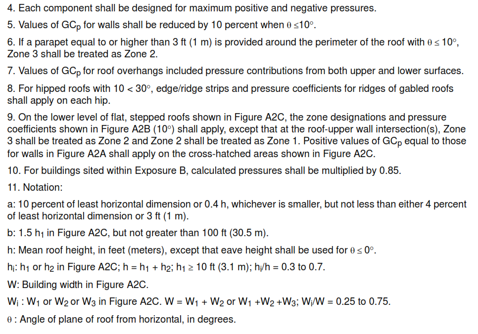
FIGURE ASCE 7-95 – Gabled and Hipped Roofs (Refer to Notes on Figure)
")
FIGURE ASCE 7-95 – Stepped Roofs (Refer to Notes on Figure)
")
FIGURE ASCE 7-95 – External Pressure Coefficients, GCp, for Loads on Building Components and Cladding for Multispan Gabled Roofs (with Two or More Spans) on Enclosed or Partially Enclosed Buildings with Mean Roof Height, h, Less than or Equal to 60 ft (18 m)

Note:
1. Vertical scale denotes GCp to be used with qh based on Exposure C.
2. Horizontal scale denotes effective wind area, A, in square feet (square meters).
3. Plus and minus signs signify pressures acting toward and away from the surfaces, respectively.
4. Each component shall be designed for maximum positive and negative pressures.
FIGURE ASCE 7-95 – External Pressure Coefficients, GCp, for Loads on Building Components and Cladding for Monoslope Roofs and Sawtooth Roofs with Two or More Spans on Enclosed or Partially Enclosed Buildings with Mean Roof Height, h, Less than or Equal to 60 ft (18 m).
FIGURE ASCE 7-95 – Monoslope Roofs (Refer to notes on Figure )
")
FIGURE ASCE 7-95 FIGURE – Sawtooth Roofs – Two or More Spans

Notes for Figures A4A and A4B:
1. Vertical scale denotes GCp to be used with qh based on Exposure C.
2. Horizontal scale denotes effective wind area, A, in square feet (square meters).
3. Plus and minus signs signify pressures acting toward and away from the surfaces, respectively.
4. Each component shall be designed for maximum positive and negative pressures.
5. For Θ≤ 3 degree (Figure A4A) and Θ≤ 10 degree (Figure A4B), values of GCp from Figure shall be used.
6. For buildings sited within Exposure B, calculated pressures shall be multiplied by 0.85.
7. Notation:
a: 10 percent of least horizontal dimension or 0.4 h, whichever is smaller, but not less than either 4 percent of least horizontal dimension or 3 ft (1 m).
h: Mean roof height, in feet (meters), except that eave height shall be used for Θ≤ 10 degree.
W: Building width, in feet (meters).
Θ: Angle of plane of roof from horizontal, in degrees.
FIGURE ASCE 7-95 FIGURE – External Pressure Coefficients, GCp, for Loads on Building Components and Cladding for Enclosed or Partially Enclosed Buildings with Mean Roof Height, h, Greater than 60 ft (18 m).


TABLE A1 * (ASCE 7-95 Table – Force Coefficients for Chimneys, Tanks, and Similar Structures, Cf

Notes:
1. The design wind force shall be calculated based on the area of the structure projected on a plane normal to the wind direction. The force shall be assumed to act parallel to the wind direction.
2. Linear interpolation is permitted for h/D values other than shown.
3. Notation:
D: diameter of circular cross-sections and least horizontal dimension of square, hexagonal or octagonal cross-sections at elevation under consideration, in feet (meters)
D’: depth of protruding elements (for example: ribs and spoilers) in feet (meters)
h: height of structure, in feet (meters)
qz : velocity pressure evaluated at height z above ground, in pounds per square foot (N/m²).