This article establishes minimum requirements for the use of filled thermal systems in process plants. Main keywords for this article are Basic Filled Thermal Systems Design Notes. Filled Thermal Systems References. Filled Thermal Systems Definitions. Filled Thermal System Application.
Filled Thermal Systems References
American Petroleum Institute (API)
RP 550 Manual on Installation of Refinery Instruments and Control Systems
RP 551 Process Measurement Instrumentation
Filled Thermal Systems Definitions
For the purpose of understanding this standard following defintions apply:
Capillary Action. Capillary action is induced by differences in surface energy between the liquid and the tube material.
Capillary Tube. A tube sufficiently fine that capillary action is significant. A tube with small internal diameter or fine hairlike construction.
Compensation. Provision of a supplemental device, circuit, or special materials to counteract known sources of error.
Diaphragm. A sensing element consisting of a thin (usually circular) plate, which is deformed by pressure differential applied across it.
Filled Thermal System. The filled thermal system shall consists of a metal thermometer or temperature-sensing bulb connected by means of a metal capillary to a receiving element located in the
instrument. The receiving element may be a bellows, diaphragm, capsule, simple Bourdon, spiral, or helix.
Basic Filled Thermal Systems Design Notes
- The installation of temperature instruments shall conform to API-RP 550/551.
- Materials shall be corrosion resistant suitable for the environment.
- Bulbs shall have bendable extension union connected with a pressure tight gland.
- Thermometers shall be over range protected.
- Vapor filled and mercury filled systems are not acceptable.
Filled Thermal System Application Considerations
- The systems are self-contained, no auxiliary power is necessary.
- System elements have sufficient power to operate either electric or pneumatic control devices.
- System simplicity permits inexpensive designs with rugged construction.
- Although response time, sensitivity, and accuracy are not as good as provided by thermocouples and resistance thermometers, they are sufficient to satisfy many industrial needs and at a lower installed cost.
- The sensing bulb is much larger than the average thermocouple or resistance thermometer bulb.
- Measurement spans cannot be as narrow as those obtainable with thermocouples, thermistors, and resistance thermometers.
- Calibration accuracy and stability require a leak-free system. When leaks do occur, the system shall be returned to the manufacturer for repair.
- The maximum distance from the sensing bulb to the readout device is quite limited when compared to thermocouple and resistance thermometer sensors. The maximum distance ranges between 50 and 200 feet, depending upon the thermal system class.
- Recalibration and range change are more difficult than for thermocouples and resistance bulbs.
- Thermowells shall be used with Filled Sensing Bulbs on any application involving high pressure, high velocity or corrosive fluids and both shall be purchased as an assembly. Click Here for Thermowell
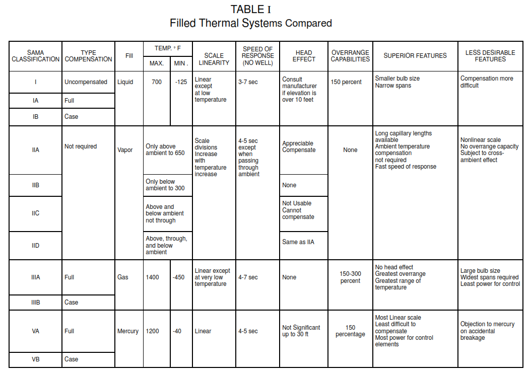
details. - The following table gives application criteria for various filled thermal systems.
