This article describes the principle of Vortex Shedding Flowmeters, application, advantages, disadvantages and installation restrictions. Reference is made in this standard to the following documents. Flow Measurement (PIP PCCFL001). Main keywords for this article are Basic Vortex Shedding Flowmeter Design Notes. Vortex Shedding Flowmeter Installation. Vortex Shedding Flowmeter Advantages. Vortex Shedding Flowmeter Disadvantages, Vortex Shedding Flowmeter Sizing, Vortex Shedding Flowmeter Calibration.
Basic Vortex Shedding Flowmeter Design Notes
- When a fluid flows past an obstacle, boundary layers of slow moving, viscous fluids are formed along the outer surfaces. If the obstacle is not streamlined, (such as a bluff body), the flow cannot follow the contours of the body on the downstream side. Separated layers become detached and roll into eddies or vortices in the low pressure area behind the body.
- The vortices are shed from alternating sides of the body. This principle is a completely natural phenomenon (such as a flag fluttering in the breeze).
- The bluff body is located in an insertion tube that extends through the centerline of the pipe. The shedding frequency is directly proportional to fluid velocity. Solid state electronic technology enables the detection of the vortices by means of pressure changes, density changes, or thermal effects in the vortex stream.
- The signals must be amplified to be used. The signals are converted to either digital frequency or analog outputs; the digital is the most accurate.
- Vortex shedding flowmeters are versatile. They feature high accuracy and wide rangeability, and require little or no maintenance. This versatility makes possible a wide range of applications that include many types of low viscosity, clean, nonabrasive liquids and gases plus steam up to 400 °F.
- Flow range is available from 5 to 3,000 gpm for water and 100 to 170,000 lb per hr of saturated steam.
- Sizes range from 1 inch to 12 inches and are usually designed to mount between flanges. Sizes 1 inch through 2 inches can have male pipe threads or integral flanges.
Vortex Shedding Flowmeter Advantages
- Good accuracy and long term repeatability.
- Rangeability is up to 20 to 1.
- Minimal maintenance, no moving parts.
- Calibration using fluid flow not required.
- Calibration is unaffected by viscosity, density, pressure, and temperature within operating specification.
- Some models suitable for gas, liquid, or steam.
- Digital or analog output.
Vortex Shedding Flowmeter Disadvantages
- Not suitable for viscous liquids.
- Cannot be easily field calibrated.
- Must be taken out of process pipe for service of vortex element.
- A minimum flow velocity is required for operation.
Vortex Shedding Flowmeter Sizing
Sizes are selected based on published minimum and maximum flow rates. The minimum flow rates are determined by the kinematic viscosity and the specific weight of the liquid. Meter body must match pipe line specification. Vendor software is usually available for sizing purposes.
Vortex Shedding Flowmeter Installation
- May be mounted vertically or horizontally. Upstream and downstream straight runs are similar to those required for orifice meters. Shutoff and bypass valves should be specified unless the line can be easily shut down and drained for service of the meter body.
- Care must be taken to mount the meter concentric to the pipe line and to make sure the gasket does not protrude into the flow path.
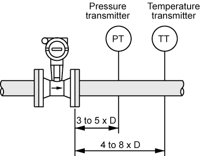
Figure 1 – Temperature and Pressure Sensors Versus Meter Run Requirements
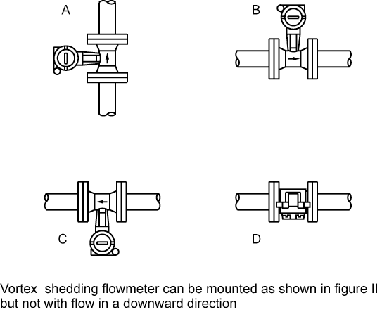
Figure 2 – Vortex Shedding Flowmeter Orientations
- Vortex shedding flowmeter can be mounted as shown in Figure 2 but not with flow in a downward direction.
Vortex Shedding Flowmeter Calibration
- Calibration is done by the manufacturer using a fluid or gas similar or identical to the process fluid. Analog output will be zero (4 mA) for all flow rates between zero and
minimum operating flow rate. - Field Checkout And Startup
- The meter should not be put into service until after the process lines have been cleaned to prevent damage due to foreign materials or excessive velocity of cleaning media. The DC analog output may be checked by introducing a frequency test signal into the electronic circuit.
- Most versions of the vortex shedding flow meter meet the requirements of Class I, Division I, Group D, for hazardous installations.

