This article is a guideline for selecting magnetic flowmeters used in process plants. Main keywords for this article are Basic Magnetic Flowmeter Design Notes. Magnetic Flowmeter Application. Magnetic Flowmeter Advantages. Magnetic Flowmeter Disadvantages.
Magnetic Flowmeter References
Reference is made in this article to the following document.
National Fire Protection Association (NFPA)
70 National Electrical Code (NEC)
Basic Magnetic Flowmeter Design Notes
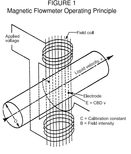
- Magnetic flowmeters operate on Faraday’s Law of magnetic induction. A conductive fluid passing through a magnetic field produces a voltage at right angles to the fluid velocity and field orientation. The electrodes sense the voltage developed. See Figure 1. For a given field intensity, electrode position, and conductor length, the voltage produced is proportional to average fluid velocity. The flow tube has a fixed area, so the developed voltage is linearly proportional to the volumetric flow rate.
- Magnetic flowmeters energize their field coils from an internally generated, pulsed dc source, at 3 to 20 Hz, depending upon model. They correct for extraneous voltages across the electrodes by measuring them when the field is deactivated, and subtracting their value from the flow signal.
- DC flowmeters with unipolar pulsing may be adversely affected by electrode polarization. DC flowmeters which reverse pulse polarity on alternate cycles avoid this problem.
- Magnetic flowmeters energize their field coils from an internally generated, pulsed dc source, at 3 to 20 Hz, depending upon model. They correct for extraneous voltages across the electrodes by measuring them when the field is deactivated, and subtracting their value from the flow signal.
- The magnetic flowmeter measures the average velocity of a conductive liquid. The flow transmitter, as shown in Figure 2, consists of a nonmagnetic tube (metal in the majority of cases, with an insulating liner); field coils which induce a magnetic field through the tube; and two electrodes diametrically opposite to each other and flush with the inside surface of the tube or liner. The electrodes have to make good electrical contact with the flowing fluid to accurately measure the very low voltage developed as the fluid passes through the magnetic field.
- Use of an integral signal converter mounted on the transmitter usually results in a higher performance and less costly installation. Errors associated with the signal cable required for remote converter
installation are avoided, which is especially important when metering low conductivity fluids. Corrosive atmospheres or electrical classification limitations may require remote converter installation. Several vendors offer both transmitters and converters labeled for NFPA 70, NEC Class I, Division 1 and 2 service. - Flow measurement is possible only with liquids of measurable electrical conductivity. Minimum conductivity for standard flowmeters is from 3 to 5 µ mho/cm. Above the low threshold limit, changes in fluid conductivity do not affect flowmeter accuracy. Tap water conductivity is approximately 100 µ mho/cm.
- The allowable length of the signal cable between the transmitter and a remote converter depends upon the fluid conductivity, flowmeter size and type. Lengths of up to 100 ft are commonly available.
- Low conductivity magnetic flowmeters are available for fluids with conductivities as low as 0.05 µ mho/cm. These are electrodeless and available with both pulsed dc and 60 cycle ac field coils. In
these units, large area electrodes are located behind the tube liner, and the generated voltage is picked up by using capacitive coupling.
- Magnetic flowmeters can accurately measure flow of many difficult-to-meter liquids. Under favorable conditions, the error will not exceed 0.5 percent of rate for most ac and dc flowmeters for flow between 10 percent and 100 percent of span. The following are recommended:
a. Electrical contact between the flowing liquid and electrodes shall be maintained. An insulating liquid film or solids buildup will cause the flowmeter to read erroneously low. The voltage at the
converter input will be lower than the voltage actually generated, by an amount equal to the voltage drop across the insulating film. b. The liquid shall be free of entrained gases and shall fill the flow tube completely to ensure measurement accuracy. Liquid containing bubbles will be metered as if it were all liquid. ‘Up-flow’ is required for inclined or vertical installations to ensure a full metering tube.
c. Flowmeter shall be installed in a stable flow location with no cavitation or flashing.
d. The liquid temperature shall not exceed the liner material temperature rating.
e. At least 5 pipe diameters of straight pipe shall be provided upstream and down stream of the electrodes. In smaller flowmeters, this requirement may be met within the length of the flowmeter flow tube.
- The effect of a buildup of conductive material on the inside of the flow tube can vary. If the buildup is concentric and of the same conductivity as the flowing liquid, then flowmeter span may be affected
considerably less than calculated from the change in tube area and fluid velocity.- The conductive buildup between the electrodes and to ground, has a complex impedance. In ac flowmeters the magnetic field induces a small voltage in this stationary path, part of which is seen at the electrodes in phase with the flow signal. Thus, changing geometry of the buildup will result in a change in zero. DC flowmeters are not affected.
Magnetic Flowmeter Application
- Magnetic flowmeter tubes range from 0.1 to 48 inches diameter with flow ranges full scale from 0.07 to 115,000 gpm. Additionally, the maximum flow rate may be extended virtually without limit by use of insertion or pitot type magnetic flow sensors. A single flow tube, with respanning, can measure a very wide range of flows.
- Maximum liquid velocity through the flow tube is 30-31 ft/s for full-scale span. Minimum velocity for full scale is typically 1 ft/s. Typical installed values are 5-15 ft/s for full scale. Velocity shall be limited to 5-10 ft/s when metering abrasive slurries, to minimize abrasion and damage to the liner.
- Flow tube can be made of a variety of nonferrous metals, ceramics, and plastics, with flow tube liners suitable for almost any liquid. Nonconductive plastic tubes do not require liners.
- Electrodes which contact the flowing fluid are available in a variety of materials, for example stainless steel, Hastelloy C, tantalum, titanium and platinum.
- Electrodes shall be mounted in the horizontal plane and kept clean. With electrodes in the vertical plane, bubbles can cause intermittent signal loss. If the metered fluid tends to coat the electrodes, they shall be cleaned periodically. The flow tube shall be sized to ensure that the full scale velocity is toward the upper maximum; the higher velocity tends to scour any coating from the electrodes. Several models have in-line electrode cleaning devices, for example ultrasonic cleaners.
- Self-cleaning electrode assemblies shall be used when required. They are intended for applications where coating or deposits may occur. The electrodes are reduced in size, mounted at an angle, and extended into the flow stream. Exposure to the higher velocity, more turbulent region, increases the scouring action.
- Power requirements are quite different for dc flowmeters, compared to ac types. The dc converter is powered from a 120 V ac line, and the dc field coils dissipate 15 to 20 W, constant for all flowmeter sizes. The ac flowmeter field coils may be supplied from 120 to 480 V ac, depending upon the tube size. Wattage increases as the tube size increases, and the electrical power factor is typically 0.1 to 0.3.
- Heat generated in the field coils will raise the liquid and tube liner temperatures under very low or no-flow conditions. Under high ambient conditions, the temperature rise can be enough to damage some tube liners. DC flowmeters have much less temperature rise than ac flowmeters.
- In addition to the standard 4 to 20 mA dc output, most converters available have scaled pulse output as an option, useful for totalizing and batching.
- Conventional flowmeters are very expensive in the larger pipe sizes, and selection of types is limited. Insertion probe and pitot tube measure flow rate in large pipes, ducts, or channels, at a reasonable cost. These flowmeters operate on the same principles as the more conventional flowmeters, with similar restrictions as to minimum fluid conductivity.
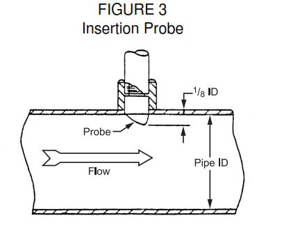
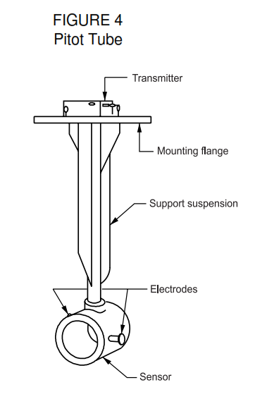
- Insertion-probe (Figure 3) and pitot-tube (Figure 4) flowmeters sense fluid velocity at a single point or location within the pipe or duct. The accuracy of the indicated flow rate depends upon the assumed relationship between the velocity at the measurement point, and the mean velocity in the pipeline. For fully developed turbulent flow, with Reynolds number ≅1 x 10⁶ or larger, empirical data indicates the velocity measured at a point which is 1/8 ID from the pipe wall, is equal to the mean velocity in the pipe. Pitot type flowmeters may have their immersion flow tube located at the pipe or duct center.
- The effect of upstream disturbances may be substantial for either insertion probe or pitot type installations. 25 pipe diameters shall be allowed between insertion probes and these disturbances.
Magnetic Flowmeter Advantages
- The volumetric flow rate measurement generated by magnetic flowmeter is usually unaffected by fluid density, consistency, viscosity, turbulence, or piping configuration.
- With the absence of moving parts and external sensing lines, and with the available Teflon liner and platinum electrodes, magnetic flowmeter is accurate and corrosion-resistant.
- With respanning, flows can be accurately measured over a very wide range with a single flow tube. Automatic or manual span switching is an option. The dc flowmeters with automatic zero do not require the flow to be stopped to establish accurate zero adjustment.
- Insertion probe and pitot tube flowmeters provide comparatively accurate flow measurement in large pipes, channels, or ducts where it may not be economically or physically practical to sense the entire stream.
- Flow tube liners are available in a variety of materials, suitable for use with almost all liquids, including abrasive slurries.
- The pressure drop through the flowmeter is the same as through an equivalent size pipe, as there is no obstruction to flow.
- Some magnetic flow systems can be used as bidirectional flowmeters, with the proper wiring circuitry, measuring flow through the flowmeter in either direction.
- Properly installed systems will achieve accuracies of 0.5 percent of rate, down to about 10 percent of full scale span, for both ac and dc flowmeters. Special calibrations for higher accuracies are also available.
Magnetic Flowmeter Disadvantages
- Magnetic flowmeters are costly, relative to other flowmeter types.
- Under very low or no-flow conditions, the heat generated in the field coils can increase the temperature of the liquid in the flow tube, and the liner.
- Maximum allowable temperature of the fluids being metered is usually limited by the liner material rating.
- AC flowmeters require the tube to be full, and flow stopped, to accurately establish zero flow signal. Accurate zero cannot be set by use of a magnetic flowmeter ‘calibrator’ because it cannot account for the nonvelocity component of the flow signal. DC flowmeters do not have this problem.
Magnetic Flowmeter Precautions
- Electrical bonding and grounding of the fluid and the flowmeter, and proper installation of signal cable to remote converters is essential. If the process piping is non-conductive, grounding rings of material corrosion resistant to the process fluid shall be used at both ends of the flowmeter.
- When sampling low conductivity liquids, to determine conductivity, care shall be taken to avoid contamination of the samples, as most sampling errors cause the measured conductivity to appear higher
than actual. - Flowmeter shall be full of fluid when metering. If stable zero signal is required, as with batching or totalizing, then the flowmeter shall remain full of liquid at no-flow conditions, or the system shall have the capability of forcing the output to zero, as from an external contact operation.
- Electrodes shall be kept clean for accurate operation. Where the application will subject electrodes to grease or sludge, as encountered in waste water or sewage, users are advised to evaluate the
performance of cleaning devices, prior to flowmeter selection. If buildup of an insulating film or precipitated solids is anticipated, then as small a flow tube as practical to keep the liquid velocity high, the installation shall be designed to keep the flowmeter full at no-flow, and, if practical, shall be used, the flowmeter shall be turned off at no-flow if higher fluid temperatures aggravate the film buildup. Solid state type converters may require up to half an hour warmup before rated accuracy is obtained, although added error during warmup will probably be small. - If metering temperature-sensitive fluids, or using low temperature rated liners, the effect of heat added from the field coils shall be considered.
- Generally, magnetic flowmeter tubes should not be insulated or heat traced, although there are exceptions. If it is deemed desirable, the manufacturer shall be consulted. If metering very low temperature fluids, it may be necessary to purge the flowmeter housing and terminal box with air or gas of sufficiently low dewpoint to avoid condensation.
- Vacuum breakers may be required for some applications, to prevent collapse of the liner.
- The velocity of abrasive slurries shall be between 5-10 ft/s to minimize abrasion, and prevent damage to the liner.


