Efficient cable tray installation and proper cable handling are critical for ensuring the reliability and safety of electrical systems. Adherence to these guidelines is essential:
Cable Tray Installation Method Statement
1. Cable Tray Installation
Cable trays should be installed in accordance with the latest revision of the NEC, NEMA VE 2, and the manufacturer’s installation instructions.
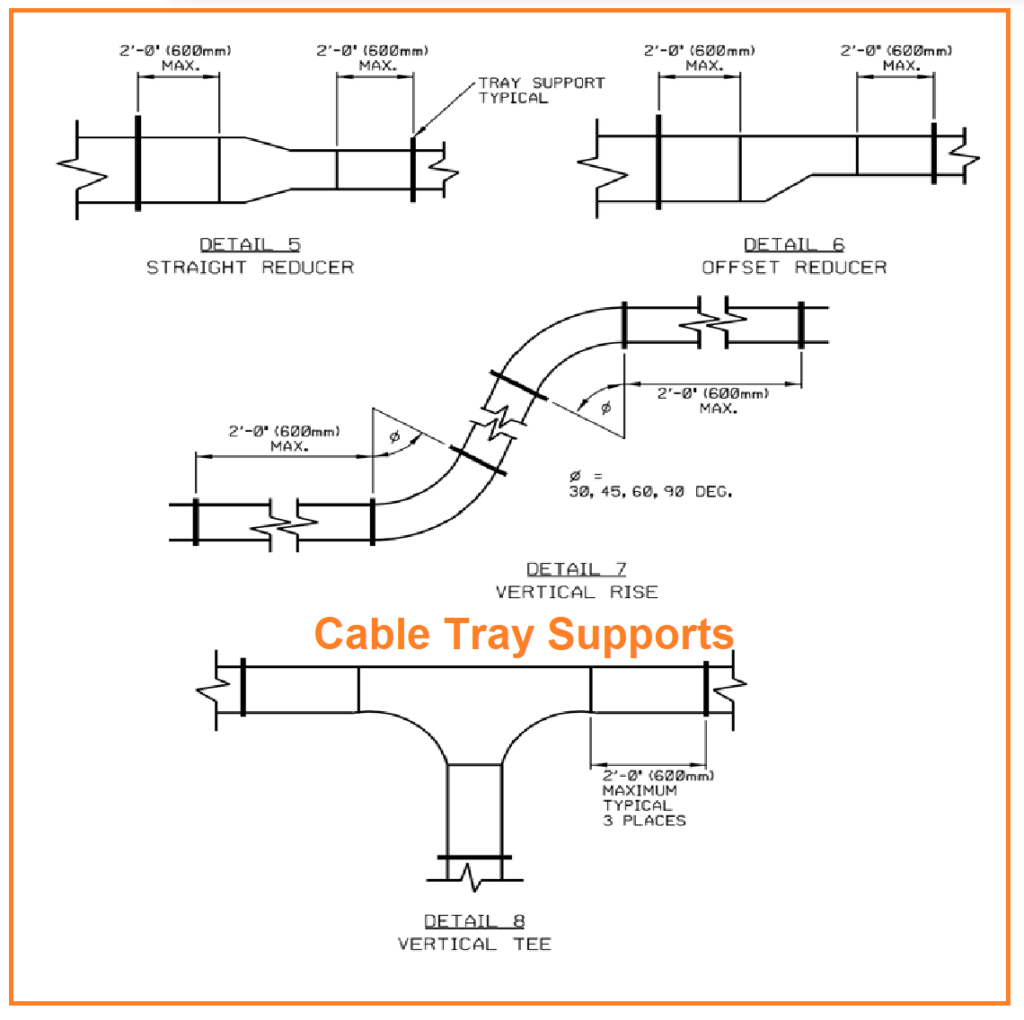
2. Support for Cable Tray Elbows
Support for cable tray elbows should conform to following figure and NEMA VE 2 requirements.
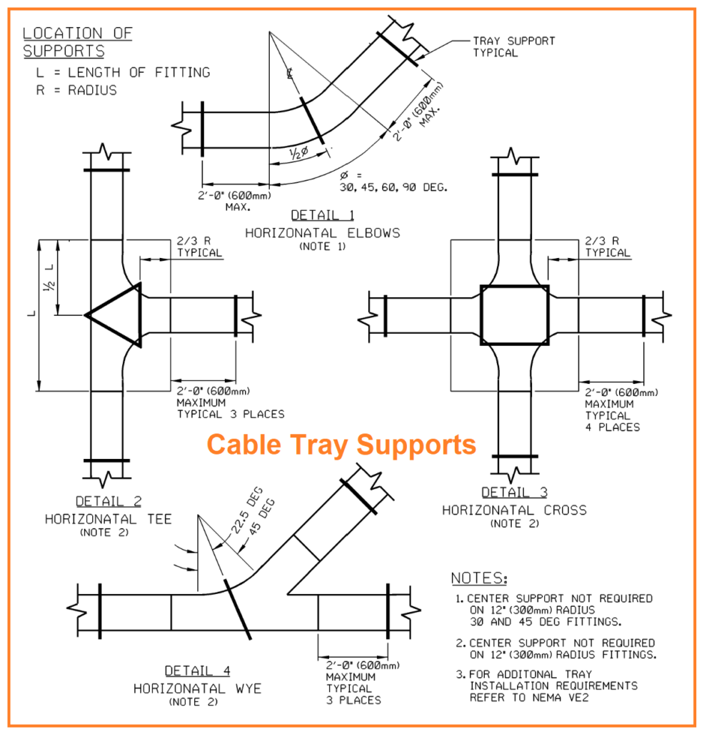
3. Cable Tray Support Locations
Cable tray supports should be strategically positioned so that connectors between horizontal straight sections of the tray fall between the support point and the quarter-point of the span. Avoid placing connectors in the center points of spans between supports or directly on supports. Cable trays should be fastened to the support system using guides that allow for longitudinal movement.
5.4.4 Expansion Connectors and Bonding
Expansion connectors must be provided at building expansion joints and in long runs of outdoor trays at intervals of 30 m (100 ft) or as specified in NEMA VE 2. A bonding jumper should be installed at each expansion joint as per STD-G309A. Ensure that all cable tray systems are bonded together with bonding jumpers.
5.4.5 Grounding of Cable Trays
Ground cable trays at least every 15 m (50 ft) and at both ends to maintain electrical continuity and safety.
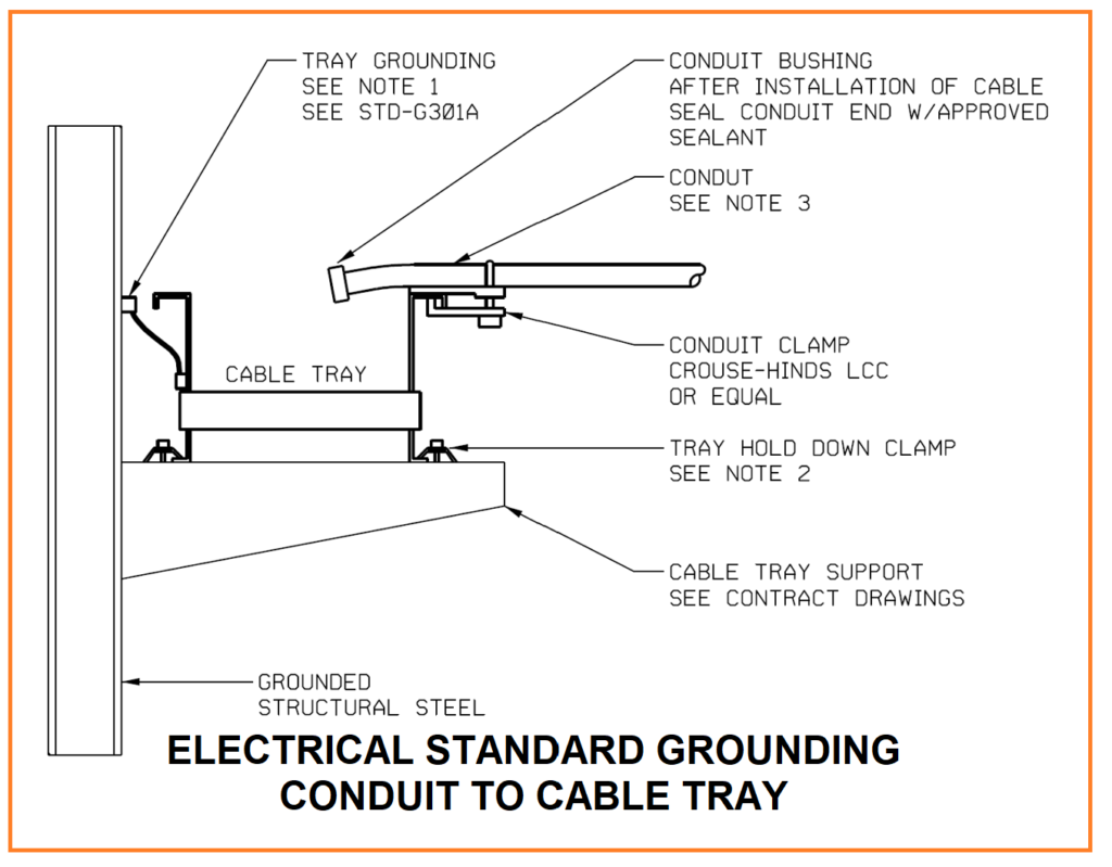
5.4.6 Bonding of Cable Tray Conduit Drop-Outs
All cable tray conduit drop-outs should be bonded to the cable tray as shown in following figure or by using a grounding bushing on the conduit end, with a bonding wire bolted to the cable tray using a compression lug.
Cable Installation
1. Proper Cable Tray Usage
Cables must be installed in the designated cable trays as specified in the contract drawings. Install cables neatly and professionally, adhering to the provided drawing details regarding cable laying and spacing within the trays.
2. Pulling of Medium Voltage Cable
When pulling medium voltage cable in cable trays, use the conductor for pulling, not the insulation or cable jacket. Remove enough cable jacket, insulation, and any other material to expose the bare conductor for effective pulling.
3. Installation of Low Voltage Cable
Low voltage cable installation should follow industry-accepted methods and employ tools designed for wire and cable pulling.
4. Use of Tension Meter/Recording Device
A tension meter/recording device must be used for all cable and wire pulls. Ensure that recorded data is available for review by the field representative engineer.
5. Rigging and Cable Pulling
Cable installation should adhere to the recommended methods and requirements of NEMA VE 2. Consider cable manufacturer data when designing cable pulls, taking into account maximum tension and sidewall pressure. Use appropriate radius pulling wheels and ensure adequate support. Exercise caution when rigging supports from existing structures, and install temporary supports if necessary for rigging equipment. It is the responsibility of the pulling contractor to prevent damage to structures, equipment, and personnel during cable pulling. It is advisable to have the rigging design approved by a qualified engineer through calculations to prevent any such damages. Cable trays should not be used to support rigging for cable installation.
6. Cable Clamps and Straps
Install cable clamps or straps suitable for outdoor use and resistant to ultraviolet light to limit the movement of conductors within the tray. Strapping should be placed at maximum intervals of 1800 mm (6 ft) for horizontal runs and 900 mm (3 ft) for vertical runs.
7. Approved Connectors for Cable Entry
Cables should enter electrical equipment using approved connectors suitable for the specific environmental conditions.
8. Protection of Cables
For cable runs outside of cable trays, use conduit or other methods as specified in the contract drawings. Support Type MC cable as permitted by the NEC, and ensure that cable runs are protected from physical damage.