This article is about Installation and Commissioning Cable Tray, Metallic Tray System for commercial buildings, plants and refinery projects as per international codes and standards.
Cable Tray QC Checking Points
| Electrical materials shall be new and unused. |
| Electrical materials shall be in accordance with the Saudi Aramco-approved project-specific design drawings, diagrams, schedules, lists, databases, and associated documents. |
| Electrical materials shall be free of damage. |
| Electrical materials shall conform to all applicable requirements, standards, and specifications prior to release to be used as part of the work. |
| Electrical materials shall be identified by using tags, stamps, color coding, stencils or labels. The location and method of identification shall not affect the function or quality of the materials. |
| Electrical materials shall be traceable from the manufacturer and supplier through delivery, storage, fabrication, erection, installation, repair, modification and use. |
Cable Tray Installation Requirements and Technical Specification
| Cable tray material shall be (a) copper-free aluminum (aluminum with a maximum of 0.4% copper). Cable trays shall be of the ladder (two side-rail) type. |
| Aluminum cable tray shall be designed, manufactured, rated, and tested in accordance with NEMA VE-1. Method A (Loading to Destruction) shall be used for determining the rated load capacity. |
| Minimum individual rung load capacity shall be 90 kg. |
| Cable tray systems shall not be used in hoistways. (NEC 392.4) |
| Cable tray systems shall not be used where subject to severe physical damage. (NEC 392.4) |
| Cable trays shall not be supported from process piping. |
| The cable tray shall never be used as a walkway. (NEC 110.3, NEMA VE-2 Sec.5.3) |
| Stainless steel cable trays shall be used when required by SAES-B-006 to satisfy fireproofing requirements. |
| Sufficient space shall be provided around cable trays to permit adequate access for installation and maintenance of cables. [NEC 392.6(I)] |
| Channel erector system components (Unistrut or similar) used to support cable tray shall be made of steel or iron, either hot-dip galvanized (preferably), or zinc electroplated as supplied by the manufacturer. |
| In severe corrosive environments, channel erector system components (Unistrut or similar) used to support cable tray and other electrical equipment shall: a) Meet all requirements as specified above (SAES-P-104 Sec.8.10.1) and be protected by: 1) Factory-coating with PVC (minimum thickness of PVC: 40 mils) per NEMA RN 1 or 2) Field coating prior to installation in accordance with SAES-H-101 APCS-22 (offshore), or APCS-26 (onshore) b) Be stainless steel or c) Be fiberglass |
| Cable trays inside substations shall be parallel and at right angles to building walls. |
| The elevation of the bottom of the lowest interior cable tray shall be a minimum of 2.67 m above the main substation floor. |
| A minimum of 460 mm shall be maintained between the top of any cable tray and the ceiling or roof joist (whichever is closer). |
| All cable trays shall have a minimum of 300 mm clear space above the tray. |
| Supports for cable trays shall provide strength and working load capabilities sufficient to meet the load requirement of the cable tray wiring system and future cable additions. (NEC 110.3, NEMA VE-2 Sec.4.2.1) |
| For straight section installation, the manufacturer recommendations for torqueing fasteners shall be followed. (NEC 110.3, NEMA VE-2 Sec.4.3) |
| Special hardware is supplied with expansion splice plates. Important—for plastic stop nut designs, tighten hardware, and then loosen 1/2 turn. For other types of hardware, follow manufacturer’s instructions. (NEC 110.3, NEMA VE-2 Sec.4.3.2) |
| Splice plates should be placed on the outside of the cable tray with the bolt heads on the inside of the cable tray (Figure 4.11). (NEC 110.3, NEMA VE-2 Sec.4.3.1) |
| Splice plates (joints) shall: 1) Not be located over supports 2) Be between supports and quarter points 3) Not be at midspan |
| No more than one splice shall be located between two adjacent supports. |
| The support span should not be greater than the straight section length. (NEC 110.3, NEMA VE-2 Sec.4.3.1) |
| The cable tray shall be anchored at the support nearest to its midpoint between the expansion splice plates and secured by expansion guides at all other support locations. The cable tray shall be permitted longitudinal movement in both directions from that fixed point. (NEC 110.3, NEMA VE-2 Sec.4.3.2, figure 4.13A) |
| The maximum spacing between expansion joints shall be based on a temperature differential of 55°C (100°F) and expansion gap settings shall be in accordance with NEMA VE 2, figure 4.13B, based on a minimum temperature of 0°C and a maximum temperature of 55°C. |
| Supports should be located within 2 ft. (600 mm) of each side of expansion splice plates. (NEC 110.3, NEMA VE-2 Sec.4.3.2) |
| Supports should be located within 2 ft. (600 mm) of each side of vertical adjustable splice plates. (NEC 110.3, NEMA VE-2 Sec.4.3.3) |
| Supports should be located within 2 ft. (600 mm) of each side of horizontal adjustable splice plates. (NEC 110.3, NEMA VE-2 Sec.4.3.4) |
Supports for horizontal cable tray fittings should be placed
within 2 ft. (600 mm) of each fitting extremity, and as follows:
a. 90° supports at the 45° point of arc.
b. 60° supports at the 30° point of arc.
c. 45° supports at the 22-1/2° point of arc
(except for the 12 in. [300 mm] radii).
d. 30° supports at the 15° point of arc
(except for the 12 in. [300 mm] radii).
(NEC 110.3, NEMA VE-2 Sec.4.4.1)
| Place horizontal tee supports within 2 ft. (600 mm) of each of the three openings connected to other cable tray items for the 12 in. (300 mm) radius. On all other radii, at least one additional support shall be placed under each side rail at the horizontal tee. (NEC 110.3, NEMA VE-2 Sec.4.4.1) |
| Place horizontal wye supports within 2 ft. (600 mm) of each of the three openings connected to other cable tray items, and at the 22-1/2° point of the arc adjacent to the side branch. (NEC 110.3, NEMA VE-2 Sec.4.4.1) |
| Cable support fittings shall be placed at the top of long vertical runs of heavy cable to support the cables. (NEC 110.3, NEMA VE-2 Sec.4.4.1) |
| Cable trays shall be installed as a complete system. Cable tray systems shall not have mechanically discontinuous segments of cable tray runs. |
| Cable tray system shall be installed with the manufacturers standard fittings, clamps, hangers, brackets, splice plates, reducer plates, blind ends, connectors, and grounding straps. |
| All fasteners (i.e., nuts, bolts, washers, etc.) used to connect and assemble the cable tray system shall be 304 SS. In severe corrosive environments, 316 SS fasteners shall be used. |
| Minimum separation between (a) power or control conductors, and (b) instrument conductors installed in cable trays shall be in accordance with SAES-J-902. |
| Cable trays shall be installed such that the minimum separation between a power cable operating at 1000 V or above, up to 34.5 kV, and a parallel or crossing power or control cable operating at less than 1000 V, shall be 300 mm. |
| Minimum separation requirements between a power or control cable and any communication conductors shall be in accordance with SAES-T-911 or SAES-T-928. |
| Cable trays with assigned cables categorized by their Noise Susceptibility Levels (NSL 1, 2 & 3), shall maintain a minimum separation as shown in SAES-J-902 Table 3 & 4. (See Attachment 2) |
| Cables with the same noise susceptibility level may be grouped in trays |
| Cable trays of instrumentation and control signal cabling (level 1 or 2) routed near sources of strong electromagnetic fields, such as large transformers, motors and generators (greater than 100 KVA), a minimum spacing of 2 meters shall be maintained between the cables and the devices. |
| Minimum separation requirements between various instrumentation cables and fiber optic data link cables shall be per the manufacturer’s recommendation. |
| When routing Instrumentation cables (level 1 & level 2) near power cables carrying higher loads than the limits specified in Level 3 (see Attachment 2), cable tray separation distances shall be 1.5 meters as a minimum. |
| Cable trays of power cables and instrumentation cables shall cross at right angles (90 degrees) while maintaining the required separation distances per Table 3 & 4 in SAES-J-902. (See Attachment 2) |
| Cable trays shall be installed such that the minimum separation between any power cable operating above 34.5 kV, and power cables operating at or below 34.5 kV, shall be 1 m. |
Cable Installation
| Low voltage unjacketed insulated wires shall not be used in cable trays (except when used as grounding conductors or listed and marked for use in cable trays). |
| Each run of cable tray shall be completed before the installation of cables. [NEC 392.6 (B)] |
| Prior to installing cable in the cable tray, examine cable paths to ensure all areas are free of debris that may interfere with the cable’s installation. (NEC 110.3, NEMA VE-2 Sec.5.3) |
| On horizontal straight runs: 1) The cable pulleys shall be spaced to prevent the cable from sagging and dragging in the cable tray during the pull. (NEC 110.3, NEMA VE-2 Sec.5.4a) |
| On horizontal bends and vertical pulls: 1) Prevent pinching the cable between the pulley flanges 2) Entry and exit angle of the cable must not exceed the maximum bending radius 3) Pulleys should be anchored to the structural steel and not to the cable tray 4) Do not pull down on the horizontal rollers (NEC 110.3, NEMA VE-2 Sec.5.4b) |
| Where all of the cables are rated 2000V or less and 4/0 AWG or larger: 1) The sum of the diameters of all cables shall not exceed the cable tray width 2) The cables shall be installed in a single layer. [NEC 392.9A(1)] |
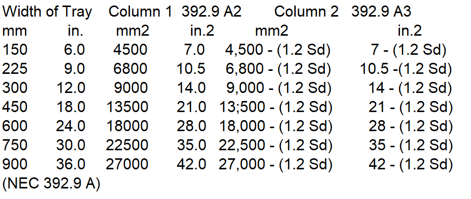
| Where all of the cables are smaller than 4/0 AWG, the sum of the cross-sectional areas of all cables shall not exceed the maximum allowable cable fill area in Column 1 of Table 392.9 for the appropriate cable tray width. [(NEC 392.9A(2)] |
| Where only multiconductor control and/or signal cables are installed in cable tray less than 150 mm deep, the sum of the cross-sectional areas of all cables at any cross section shall not exceed 50 percent of the interior cross-sectional area of the cable tray. (NEC 392.9 B) |
| A depth of 150 mm (6 in.) shall be used to compute the allowable interior cross-sectional area of any cable tray that has a usable inside depth of more than 150 mm (6 in.). (NEC 392.9 B) |
Table 392.9
Maximum Fill for Multiconductor Cables 2000V or less:
| Single-conductor cable shall be: 1) 1/0 AWG or larger 2) Listed and marked for use in cable tray 3) Have a maximum rung spacing of 230 mm [NEC 392.3 B1(a)] |
| For cables 250 kcmil up to 900 kcmil, the sum of the cross-sectional areas of all single conductor cables shall not exceed the maximum allowable cable fill area in Column 1 of Table 392.10 (A) for the appropriate cable tray width. (NEC 392.10 A2) |

| For cables rated 2001 volts or greater: 1) The sum of the diameters of single-conductor and multiconductor cables shall not exceed the cable tray width 2) The cables shall be installed in a single layer. (NEC 392.12) |
| Where single conductor cables are triplexed, quadruplexed, or bound together in circuit groups: 1) The sum of the diameters of the single conductors shall not exceed the cable tray width 2) The groups shall be installed in single layer arrangement. (NEC 392.12) |
| The drop-outs and drop-out bushings provide a smooth surface to protect the cable insulation as it exits the cable tray. (NEC 110.3, NEMA VE-2 Sec.4.6.2) |
| When using cable clamps, the clamps shall be sized correctly and only tightened enough to secure the cable without indenting the jacket. (NEC 110.3, NEMA VE-2 Sec.5.6) |
| When using cable ties, the ties shall be sized correctly and only tightened enough to secure the cable without indenting the jacket and they should be applied with pressure limiting device. (NEC 110.3, NEMA VE-2 Sec.5.6) |
On long vertical drops, intermediate supports should be installed on the vertical drop to break the cable load into segments supported at multiple places. Cables are fastened a minimum of every 18 in. (450 mm) on vertical runs. (NEC 110.3, NEMA VE-2 Sec.5.6)
Cable Tray Commissioning
| Cable trays shall not have sharp edges, burrs, or projections that could damage the insulation or jackets of the wiring. (NEC 392.5 B) |
| For individual conductors transitioning out of the cable tray, the distance between cable trays and equipment shall not exceed 1.8 m (6 ft). The conductors shall be secured to the cable tray at the transition, and they shall be protected from physical damage. (NEC 392.6 A) |
| Supports shall be provided to prevent stress on cables where they enter raceways or other enclosures from cable tray systems. (NEC 392.6 C) |
| The drop-outs and drop-out bushings provide a smooth surface to protect the cable insulation as it exits the cable tray. (NEC 110.3, NEMA VE-2 Sec.4.6.2) |
| Cables rated over 600 volts and those rated 600 volts or less installed in the same cable tray shall comply with either of the following: 1) The cables rated over 600 volts are Type MC or (2) The cables rated over 600 volts are separated from the cables rated 600 volts or less by a solid fixed barrier of a material compatible with the cable tray. (NEC 392.6 F) |
| For raceways terminating at the tray, a listed cable tray clamp or adapter shall be used to securely fasten the raceway to the cable tray system. (NEC 392.6 J) |
| Metal cable tray expansion joints and stainless steel splice plates shall be bonded in accordance with NEC Table 250.122. (See Attachment 1) (NEC 110.3, NEMA VE-2 Sec.4.7.1, NEMA VE-2 Sec.4.7.3.2) |
| Metallic cable trays shall be bonded to the local ground grid or ground electrode at both end points ensuring that bonding continuity is met throughout all the racks in the system. |
| Bare copper EGC cable shall not be used in or on aluminum cable tray. (NEC 110.3, NEMA VE-2 Sec.4.7.2) |
| Single conductors used as equipment grounding conductors shall: a) Be insulated b) Be 4 AWG or larger c) Sized in accordance with NEC Table 250.122 [NEC 110.3, NEC 392.3 B1(c)] |
| The working load shall not exceed the rated load capacity of the cable tray defined in NEMA VE 1 (destruction load divided by a safety factor of 1.5). |
| Deflection of the cable tray system when loaded to the working load as defined in paragraph 9.4, excluding the concentrated static load, shall not exceed L/100 (L=span length). (e.g., maximum permissible deflection for a 6 m span is 60 mm). |
| Minimum thickness of covers shall be 1 mm. |
| End plates shall be installed for cable tray dead end closure. (NEC 110.3, NEMA VE-2 Sec.4.3.9) |
| Cable tray installed outdoors shall have ventilated covers. |
| Cable trays run vertically in outdoor areas shall have covers on both sides. |
| Flanged type covers shall be secured with stainless steel banding, one band per ½ m of cover length, with a minimum of six bands per cover. |
| All wall penetrations to be sealed with approved methods to maintain the fire resistance rating. (NEC 300.21) |
International Codes & Standards for Cable Tray Installation
| 3. NFPA 70 – National Electrical Code (NEC), 2008 Edition |
| 4. SAES-P-104 – Wiring Methods and Materials, 13 January 2008 |
| 5. SAES-P-119 – Onshore Substations, 21 August 207 |
| 7. SAES-P-111 – Grounding, 16 July 2006 |
| 8. Unistrut Metal Framing – Application, Installation, Specification Guide, 1997 |
| 9. SAES-H-101 – Approved Protective Coating Systems, 29 June 2005 |
| 10. National Electrical Manufacturers Association NEMA RN 1 -2005 – PVC Externally Coated Galvanized Rigid Steel Conduit |
| 11. National Electrical Manufacturers Association NEMA VE1-2002 – Metal Cable Tray Systems |
| 12. National Electrical Manufacturers Association NEMA VE2-2006 – Cable Tray Installation Guidelines |