This article is about In-House Calibration of Temporary Pressure Gauge and Pressure Relief Valves for Piping Pressure Test. Following are the table contents
- PURPOSE
- SCOPE
- APPLICABLE DOCUMENTS
- RESPONSIBILITY
- MANPOWER
- TOOLS & EQUIPMENT
- GENERAL REQUIREMENTS
- METHODS / PROCEDURES
- QUALITY CONTROL
- SAFETY PRECAUTION
- ATTACHMENTS
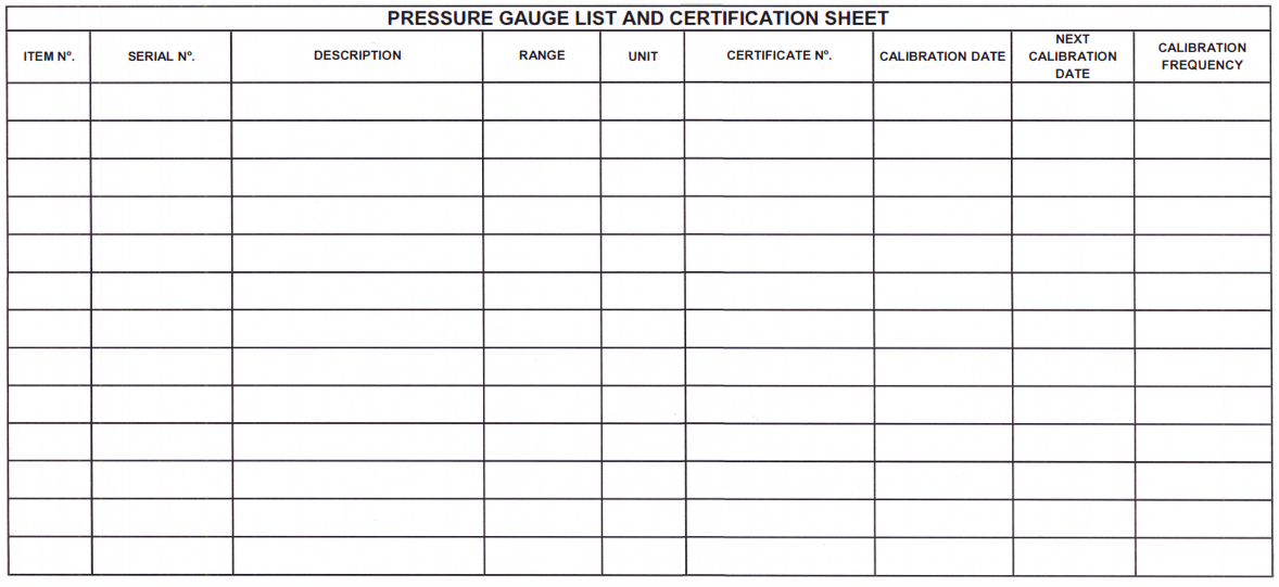
PG List and Certification Sheet
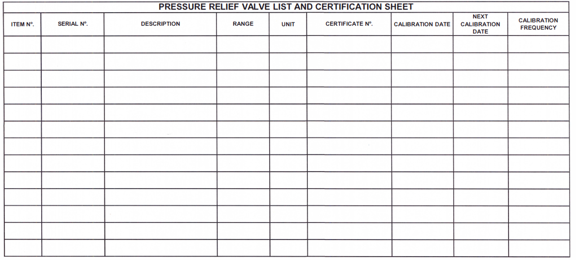
PRV List and Certification Sheet
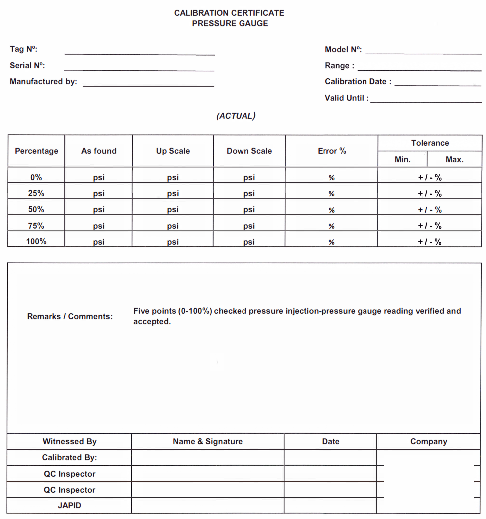
Calibration Certificate (Pressure Gauge)
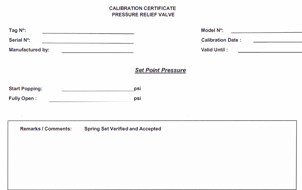
Calibration Certificate (Pressure Relief Valve)
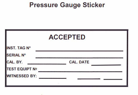
Pressure Gauge Sticker
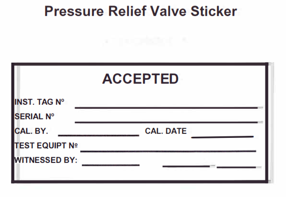
Pressure Relief Valve Sticker
1.0 PURPOSE
1.1. This method statement shall provide minimum guidelines to carry out In-house calibration for temporary pressure gauge and pressure relief valves for piping pressure test at Buildings, plants and refineries. In accordance with contract scope of work and project specification.
2.0 SCOPE
2.1. This Method Statement covers the procedure of In-house calibration for temporary pressure gauge and pressure relief valves for piping pressure test.
3.0 APPLICABLE DOCUMENTS
3.1. Saudi Aramco Standard
3.1.1 SAEP-302 Instruction for obtaining a waiver of a mandatory Saudi Aramco Engineering requirement.
3.1.2 SAES-J-002 Technical Acceptable Instruments Manufacturers
3.1.3 SAES-J-600 Pressure Relief Devices
3.1.4 SATIP-J-200-01 Pressure Instrumentation
3.1.5 Gl-0002.102 Pressure Testing Safely
4.0 RESPONSIBILITY
4.1. Construction Manager shall implement HSE requirements for the job and shall study, analyze and schedule all construction activities with his department to include manpower and equipment line up as well as other possible resources required for the successful implementation of the construction work activities. He shall study all aspects of work procedure as per Technical Scope of Work.
4.2. Piping Supervisor shall be directly reporting to construction manager and responsible for the implementation and control of all activities as per Technical Scope of Work and latest approved for construction drawings. He shall also designate a responsible staff that shall be in charge for execution of work to ensure that schedule, plans and allocations shall be followed and avoid unnecessary delays and obstructions.
4.3. Instrumentation Foreman shall be responsible for the direct work supervision and ensures that the works are performed in accordance with Technical Scope of Work and in conformance with applicable codes, standards, specifications and approved procedures.
4.4. QC Inspector shall be responsible for inspection and monitoring of the testing activity and ensure that the testing activities is performed and properly documented in accordance with Project requirements.
4.5. Safety Supervisor shall be responsible for monitoring safety aspects and ensuring that the testing activity is done in accordance with Safety Standard Procedure. He shall discuss with the workers the characteristics of related materials and status of work area giving reminders as an additional point to work safely.
5.0 MANPOWER
5.1. The Instrument Supervisor shall control the overall activities at site and he will be
directly reporting to Construction Manager. The basic manpower under him shall
consists but not limited to the following:
5.1.1. Instrument Foreman
5.1.2. Instrument Technician
5.1.3. Helpers
5.2. Safety Engineer/Officer
5.3. QC Inspector
6.0 TOOLS AND EQUIPMENT
6.1. Tools and equipment needed should be in good condition and must be checked by Instrument Supervisor I Safety Officer prior to use. These includes but not limited to:
6.1.1. Tools & Equipment
6.1.1.1 Dead Weight Tester
6.1.1.2 Comparator (Calibrated by Third Party)
6.1.1.3 Pressure Gauge (for calibration)
6.1.1.4 Pressure Relief Valve (for calibration)
6.1.1.5 Test Rig
6.1.1.6 Set of Instrument Tools and Fittings
7.0 GENERAL REQUIREMENTS CALIBRATION OF PRESSURE GAUGE & PRESSURE RELIEF VALVES
7.1 Calibration equipment to be used shall bear valid calibration certificates traceable to the national standard indicating calibration validity. All primary calibration equipment shall be initially calibrated and periodically checked by a third party laboratory testing facility.
7.1.1. Calibration of pressure gauges and pressure relief valve shall comply with the basic requirement as per JGC/DAEWOO/Saudi Aramco Standards and manufacturer’s instructions.
7.2. Provide separate rack for instrument needed for calibration and calibrated one. Instruments shall be calibrated in a fully air-conditioned, clean and dry calibration workshop. Ensure daily housekeeping before and after the work. Use appropriate vacuum cleaner and rugs to keep away dirt/foreign materials. Calibration room must be restricted to unauthorized personnel.
7.3 Only qualified instrumentation technician are authorized to perform testing and calibration of instrument.
7.4 Instruments shall be checked as per Instrument Specification Sheet.
7.5 Calibration of each kind of instrument shall be covered by individual invitation for Inspection and Testing to be witnessed by Contractor Company/Client Representatives. shall give Contractor and Client Representatives a minimum of 24 hours and 48 hours for weekend notice of intention to carry out the test.
7.6 The pressure gauges and relief valves shall be identified by its serial number and checked against its original datasheet when purchased ensuring that it is within its applicable test ranges.
7.7 Calibration shall be done.as per manufacturer’s instruction, where available.
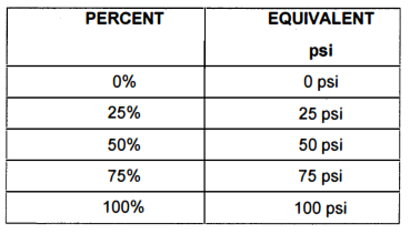
7.8 For all gauges calibration where applicable, five (5) points testing methods shall be followed, 0%, 25%, 50%, 75%, and 100%. After successful completion of each calibration, the instrument shall be marked with calibration sticker bearing the date of the calibration and the initials of the witnessing party.
7.9 Calibration facility is located at SAACO workshop area see attachment 7 for more details on calibration facilities location.
7.10 Calibration of temporary pressure gauges and pressure relief valves for piping pressure test.
7.11 Maximum pressure of nitrogen for PZV popping test is 1800 psi. If PZV needs more pressure we will calibrate it by deadweight tester instead of popping test.
7.12 For pressure gauges as per SAES-A-004 para. 8.1.5.2 “The calibration interval shall not exceed one (1) month prior to the test date and calibration certificates shall be made available to Inspection personnel prior to commencement of the pressure test. Stickers shall be applied indicating the latest calibration date”.
7.13 For pressure relief valve as per SAES-A-004 para. 5.5.1 ‘The relief valve(s) shall be tested, dated, and tagged within one week prior to the pressure test for new construction projects”.
7.14 The comparators are sent for re-calibration/certification every three (3) months to accredited 3rd party Aramco Approved Calibration Nendor.
8.0 CALIBRATION OF PRESSURE GAUGE & PRESSURE RELIEF VALVES | METHODS I PROCEDURE
8.1 Using Deadweight
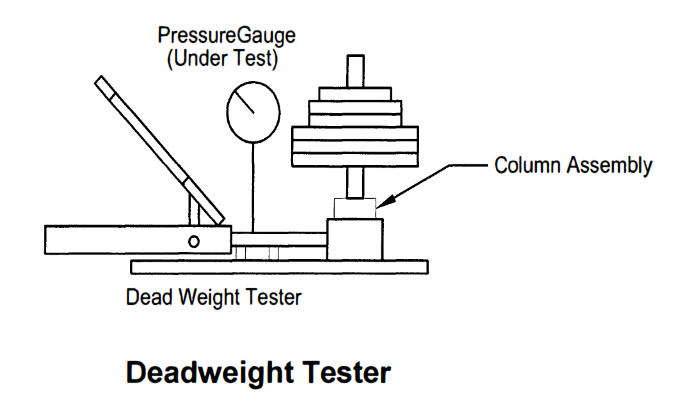
8.1.1 The pressure in the deadweight system is produced by means of a capstan operated hydraulic ram, balanced by deadweight acting upon a piston of known area. Oil is used as the hydraulic fluid.
8.1.2 Set up the equipment needed for calibration. Know first the maximum capacity of the deadweight tester whether it can accommodate the range of the gauge to be calibrated.
8.1.3 A spirit level and adjustable feet shall be provided to enable the operator to level the instrument. A flotation indicator mounted on the top plate removes the guesswork when floating the piston.
8.1.4 Prepare the manual and data sheet that will be used for details of the instrument to be calibrated. Some information needed for calibration to be inputted to data sheet are:
8.1.4.1 Equipment name
8.1.4.2 Pressure Range
8.1.4.3 Serial No.
8.1.4.4 Date of Calibration
8.1.4.5 Date of Next Calibration
8.1.5 Wrap the gauge fitting with Teflon tape (clockwise direction).
8.1.6 Place the gauge to be tested to the manifold assembly (with gauge fitting match to the manifold joint). Use correct size of wrench, and make sure there is no leak.
8.1.7 If the gauge to be tested has for example, 0 to 100 psi range, use 5point scale as reading reference. Other gauges may have higher ranges. This rule holds to kinds of pressure gauges.
0% – low pressure (zero reading)
100% – high pressure (full scale reading
8.1.8 The pointer’s initial reading shall be 0 psi. If not, zero adjustment shall be made.
8.1.9 Place weights on the cylinder corresponding to each point scale of the pressure gauge. Increase the actuating pressure equivalent to 0%, 25%, 50%, 75% and 100% of the assigned range.
8.1.10 Tightly close the release valve by turning it clockwise.
8.1.11 Pump gently until its weights floats to an ideal level.
8.1.12 Rotate weights clockwise very gently and continuously while pumping.
8.1.13 If cylinder base exceeds above or below the ideal level, rotate fine pressure adjustment lever.
8.1.14 Record the pointer indication values for each point-scale. This is the “AS-FOUND” data.
Upscale (0%, 25%, 50%, 75% and 100%)
Downscale (100%, 75%, 50%, 25% and 0%)
8.1.15 If the “AS-FOUND” data exceeds the required accuracy, calibration shall be done. A zero or span adjustment shall be made.
Zero adjustment – minimum scale value
Span Adjustment – maximum scale value
SPAN = Maximum range-Minimum range
8.1.16 Repeat the procedure until the readings for each point scale is within the specified limits of accuracy.
8.1.17 Record the readings for each point-scale and this is the “AS-LEFT” data. When done, release the built system pressure by opening the release valves.
8.1. 18 When done, release the built system pressure by opening the release valve.
8.1.19 Results shall be filed and recorded on applicable forms as per SATIP-J200-01.
8.2 Relief Valve Popping Test
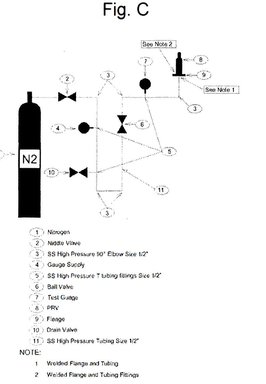
8.2.1 Connect the relief valve to a suitable test rig prior in building up the test pressure. Refer to Figure. C.
8.2.2 The gauge (Comparator) should be firmly fixed to a bench. A test gauge of range comparable to the relief valve under test is fitted to one branch of the comparator. The valve to be tested is fitted to the other branch and the test gauge on comparator in order to check the valve against the readings of the test gauge. Reading shall be tested/checked on the pressure of the relief valve and will popped on the exact pressure.
8.2.3 Apply nitrogen gas such that the reading will be checked on the pressure setting of the relief valve and will popped on the exact pressure.
8.2.4 Standard Test gauges (comparator) shall have an accuracy of or better than 0.25% of full scale and shall be periodically checked. Test gauges (comparator) are sent for re-calibration/certification every three (3) months to accredited 3rd party Aramco Approved Calibration Nendor.
8.2.5 After the tests have been completed, the relief valve shall be identified with accepted sticker.
8.2.5.1 All calibrated relief valves shall have calibration certificate.
8.2.6 Results shall be filed and recorded on applicable forms as per SATIP-J-200-01.
9.0 QUALITY CONTROL
9.1 All Testing and Inspection shall be coordinated with by Inspector.
9.2 Inspector shall be responsible to conduct all required inspection documentation and to ensure that all applicable requirements, codes and standards are being complied.
9.3 QC Inspector has to utilize the applicable inspection and test forms reflected on approved SATIP.
9.4 QC Inspector shall be assigned to ensure the quality control and assurance on requirement of the project.
10 SAFETY PRECAUTION
10. 1 Secure the approved work permit from the concerned JAL Representative before starting any work.
10.2 All electrical tools shall be check and color coded.
10.3 Continuous monitoring and checking shall be conducted by concerned supervisor/foreman to detect and correct unsafe practices while performing the work activities.
10.4 Provide warning sign and sufficient barricade on working areas to avoid unauthorized entry. Only assigned personnel shall be allowed in the area.
10.5 Housekeeping shall be maintained and working areas shall be kept clean and tidy in accordance with the Site Housekeeping Procedure.
10.6 Risk Assessment of this procedure shall be disseminated and explained to all involve personnel for safety awareness
11 ATTACHMENT
Attachment 1 PG List and Certification Sheet
Attachment 2 PRV List and Certification Sheet
Attachment 3 Calibration Certificate (Pressure Gauge)
Attachment 4 Calibration Certificate (Pressure Relief Valve)
Attachment 5 Pressure Gauge Sticker
Attachment 6 Pressure Relief Valve Sticker
