Main tests are Transformer testing, transformer oil testing, transformer winding, current transformer, Transformer Ratio test.
TRANSFORMER TESTING ON SITE
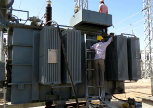
After a transformer has been completely assembled on site, it must be tested to confirm successful shipment and correct assembly. All tests must be carried out with instruments that have traceable, valid calibration. These instructions are intended to provide guidelines in the test of transformers to maintain their quality and reliability.
They are intended for the guidance of personnel who have been trained for, or who have experience in test of high-voltage electrical power equipment, including the use of good safety practices. These instructions are intended to supplement, and not eliminate the necessity for such training.
The Transformer testing results are to be recorded on a Test Record. The second sheet of this Transformer testing Record is a list of all possible tests, some of which may not be applicable. When the on-site project manager or the assembly supervision has marked all applicable tests, this sheet forms an order-bound directive for the tests to be carried out.
Main tests are Transformer testing, transformer oil testing, transformer winding, current transformer,Transformer Ratio test.
Transformer Ratio test
The Transformer Ratio test is used to confirm that the winding turns ratio is consistent with the voltage ratio as shown on the Nameplate.
Transformer Ratio test
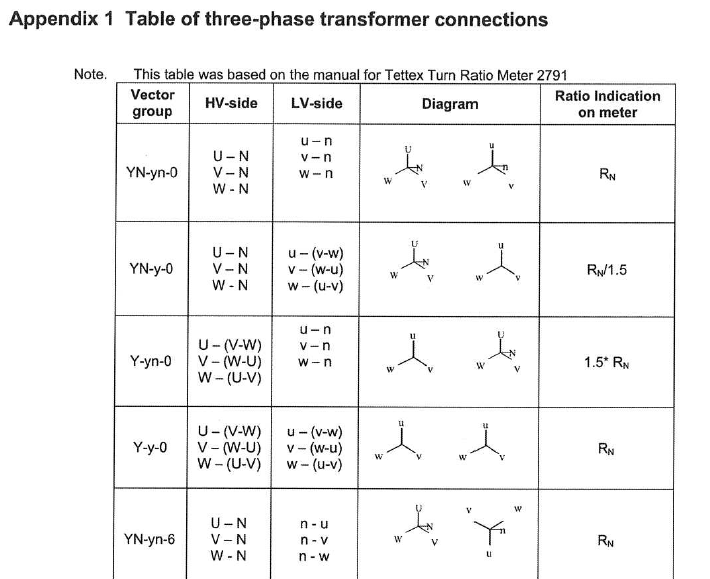
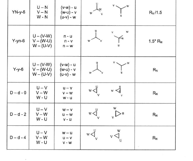
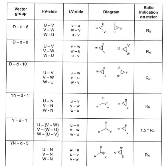
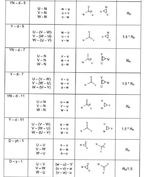
This is done primarily to check for shipping damage and to confirm that any tap-changer leads installed in the field have been correctly connected. In addition to the ratio measurement, exciting current is also often measured. The ratio measurements is normally done with a ratio bridge. Table of three-phase transformer connections Appendix 1. Transformer Ratio test
Transformer Winding resistance test
Measure the resistance of each winding at the rated and extreme tap positions and compare the results to the original value in the Factory test report. If the Tap Changer connections have been made at site, measuring at all positions should be done. Transformer winding Resistance is dependent on the temperature of the winding. The mean temperature of the oil is representative of the winding temperature, and providing that the oil is at a uniform temperature, the top oil temperature gauge value can be used. Resistance comparison must always be made at a common temperature. The conversion formula for copper and aluminium transformer winding is show below. The formula giving the relation between the resistance and the temperature is:
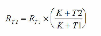
where RT2 = Resistance of the winding at temperature T2
RT1 = Resistance of the winding at temperature T1
K = 234.5 for winding made of copper ace to IEEE,
K = 235 for winding made of copper ace IEC
K = 225.0 for winding made of aluminium
The time constant may be very long when low voltage and low current sources are used.
Note:
A high voltage surge occurs at interruption of DC current at end of measurements. A discharge circuit should be used. Eg. see IEEE Std 62 figure 2.
Main tests are Transformer testing, transformer oil testing, transformer winding, current transformer, Transformer Ratio test.
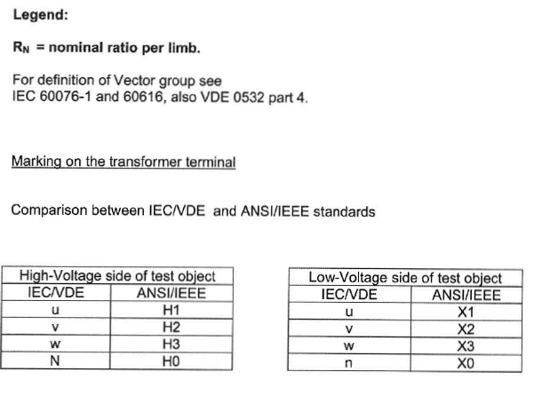
Transformer Check of vector group
The purpose of this series of tests is to check the polarity and the phase relationship of the multiple windings in a transformer. The test is carried out simultaneously with the transformer turns ratio test when using a turns ratio test set. In order to define the connection of a three-phase transformer and to facilitate the parallel connection with other transformers, the international standards prescribe specific vector groups. Every country has its own designation for the vector groups. IEC and IEEE (in USA) have recommended a method that will result in standardized and fully defined designations.
Transformer Insulation resistance test
Insulation resistance can give some information of the integrity of the insulation structure. As an insulation structure begins to deteriorate due to contamination and moisture, the insulation resistance will decrease. The test equipment used is a DC insulation tester (Megger). It is essential that it is of a type, which is suitable for measurement on transformers and transformer core insulation. Ensure that bushings are clean and dry. Insulation resistance is temperature dependence why it is important that the oil temperature is noted.
After the test has been completed, all terminals shall be grounded time enough to allow any trapped charge to decay to negligible value.
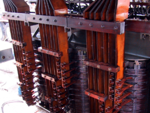
Transformer main windings
When conducting an insulation resistance test on transformer windings, a 2.5 or a 5 kV megger can be used. Test every winding to ground and between each winding. Make sure that the bushing porcelains are cleaned since dirt deteriorates the insulation resistance. The transformer tank must be grounded during the test. If the insulation resistance is 1 Mn/kV system voltage for the winding, it is acceptable. If lower values are measured, this must be reported to an ABB representative.
According to IEEE the following shall be measured. High voltage to low voltage and ground, low voltage to high voltage and ground.