
GENERAL METHODS OF PROTECTION OF INSTRUMENTS
The general methods of protection of instruments shall include but are not limited to:
(1) Insulation of the instrument including tubing and piping to prevent heat loss or gain.
(2) Tracing the instrument including tubing and piping
• All tracing of instruments shall account for Manufacturer recommendations regarding maximum temperature of operation.
• Where tracing is to be used, care shall be taken to ensure that overheating of the process fluid does not occur.
(3) Purging or flushing the instrument including tubing and piping to prevent undesirable liquids, solids or gases from entering the instrument or impacting its performance.
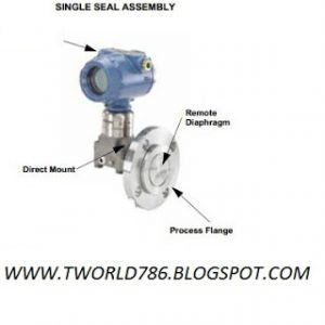
(4) Isolating the instrument from the process fluid through the use of a diaphragm seal.
(5) Isolating the instrument including tubing and piping from the process fluid through the use of a sealing liquid, noting the following:
• Sealing liquids shall be immiscible/ compatible with the process fluid.
• Water may be used as a sealing liquid where the only purpose is to protect against the entry of the process fluid.
• An instrument may be sealed with a liquid having a low freezing point (e.g.: dibutyl phthalate at –35°C or 50%, ethylene
glycol in water at –36 °C).
• Instruments with a low (negligible) displacement may be sealed without the use of seal pots.
Instruments with appreciable displacement require seal pots with special piping arrangements for control of the seal liquid level in order to prevent hydrostatic errors.
• Instruments that have sealed leg installations should only have legs filled by qualified personnel. Warning labels should be attached to vent/drain connections.
(6) Isolating the instrument and piping from entrained fluids by use of vapor/liquid separators.
Special consideration shall be given to protection method(s) used, where hazardous/toxic fluids are handled. Protection philosophy in these cases shall be to contain the process fluid as close to the process (e.g. piping/vessels) as possible, even when the instrument system materials do not necessarily require protection.
(8) Design and installation of systems shall be such that pockets, crevices, etc. are minimised in order to prevent undesirable build up of hazardous/toxic material.
(9) In some cases, a suitable means of flushing or purging may be required (either continuous or intermittent).
(10) Enclosing the instrument in an insulated housing (where possible equipment shall be specified for the appropriate climatic conditions).
(11) Care shall be taken to ensure temperatures at the instrument to be kept within manufacturer’s tolerances.
(12) Where necessary, personnel protection shall be applied to instrument piping.
(13) Sunshades shall be provided where levels of solar radiation could cause excessive heat within an instrument and affect
its operation or accuracy. Other methods of protection may be used.
(14) The use of NACE compliant trims for corrosive services where applicable.