CCR Reactor Site Assembly Installation Procedure
Contents
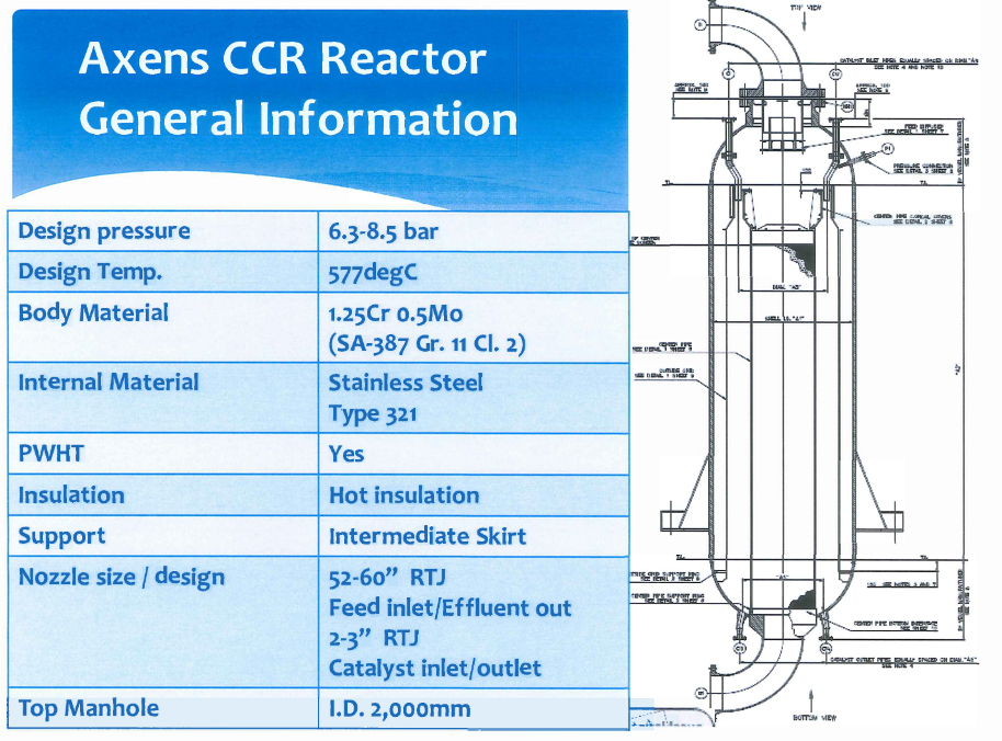
► CCR Reactor General Information
►CCR Reactor Internal Parts
►CCR Reactor Layout
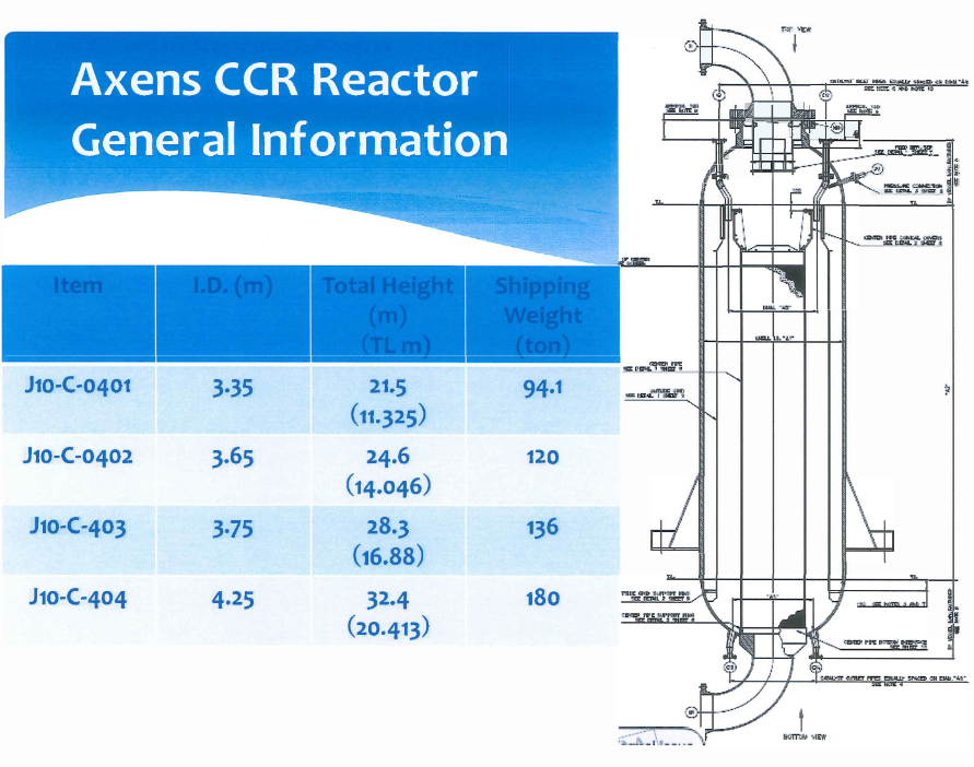
CCR Reactor General Information
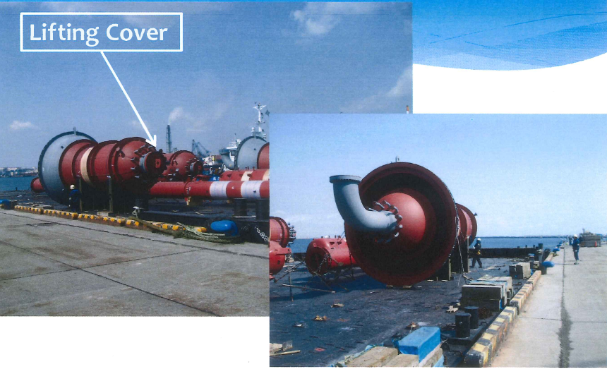
CCR Reactor Shipping Condition
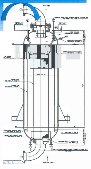
CCR Reactor Internal Parts
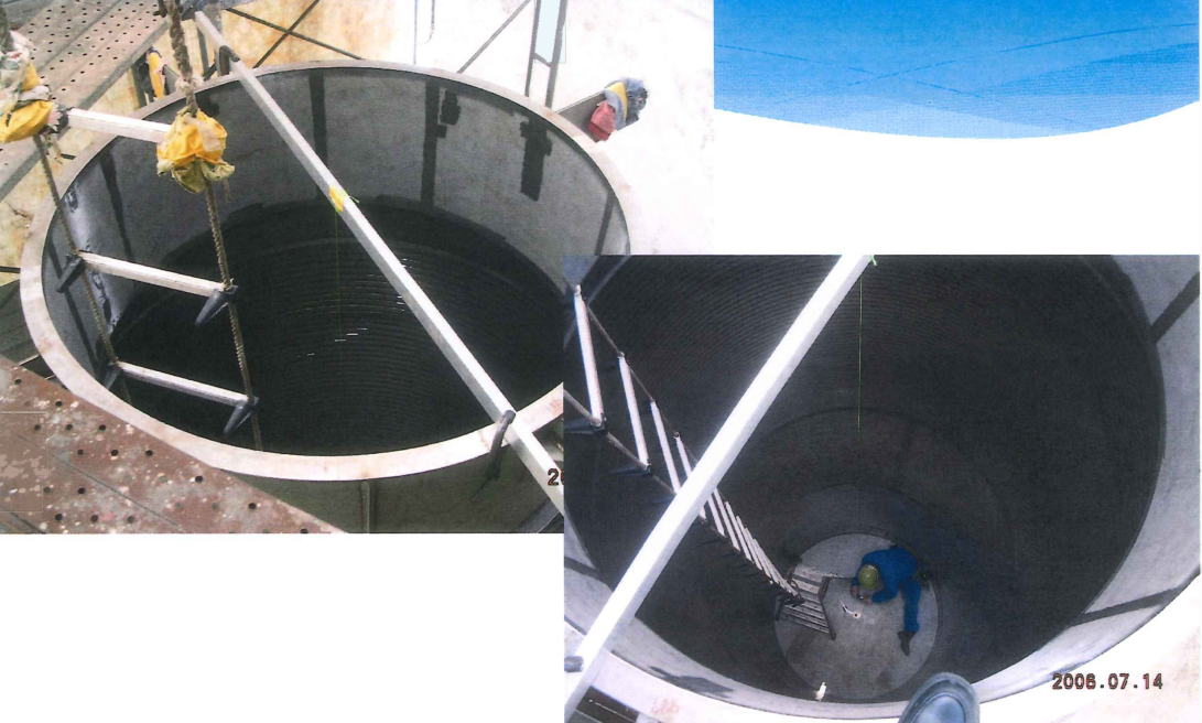
Access way only form Top Manhole (1.D. 2000 mm )
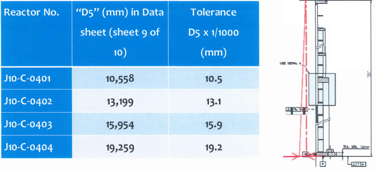
► Plumbness and clearance requirement for catalyst tight
► Confined space in the Reactor
► Smooth flush on welding bead of catalyst contact face
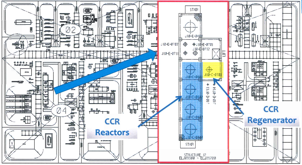
► Layout in the CCR unit structure
CCR Reactor Internal Parts Information
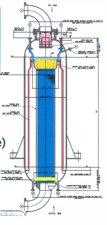
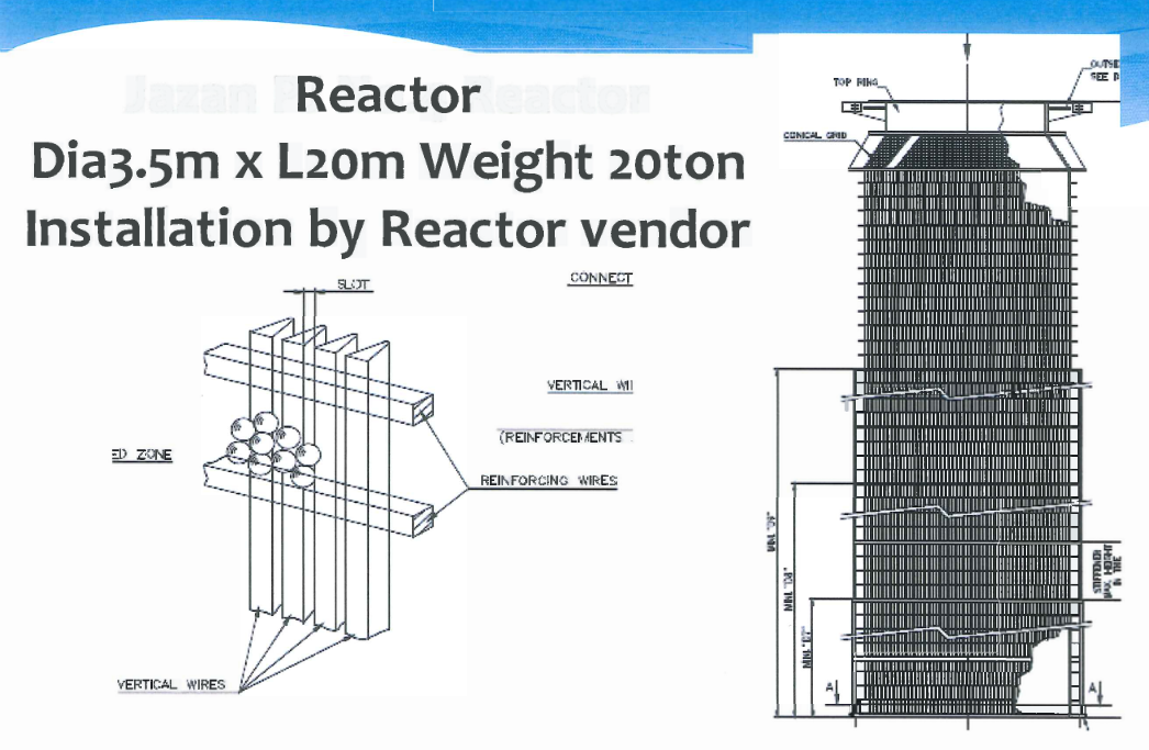
Feed Diffuser Outer grid
- Center Pipe.
- Sealing ring (3pcs/segment type).
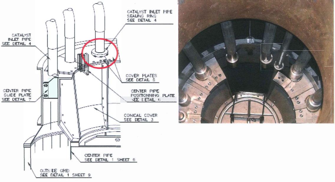
- Conical cover (6pcs/segment type).
- Cover Plate(12pcs/segment type).
- Catalyst transfer pipe(12pcs/Rx) with sealing ring.
Installation by Rx vendor at shop.
CCR Reactor Internal Scope of Inspection
Parts |
Trial assembly |
Location for trial assembly |
Final Installation |
| Outside Grid | Same allocation in the reactor |
Internal vendor shop | Reactor vendor |
| Center pipe | Conical cover and cover plate shall be installed to center pipe in vertical position | Site | |
| Conical cover | same as above | Site | |
| Cover plate | same as above | Site | |
| Catalyst inlet pipe Seal Ring Associated stopper | Inspection alone Flange neck to be welded at site. | Internal vendor shop | Site |
| Sealing ring | Fitting with center pipe | Internal vendor shop | Site |
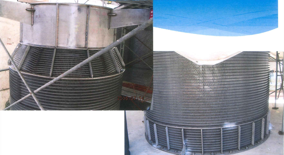
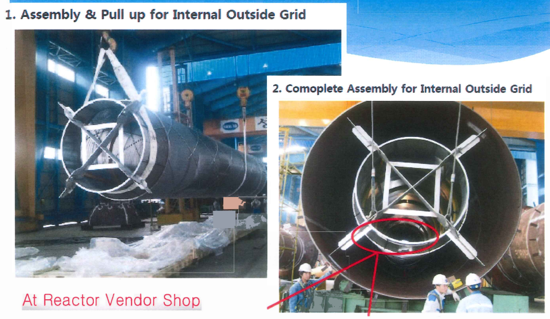
CCR Reactor Internal Outside Grid
Outside Grid Top Section
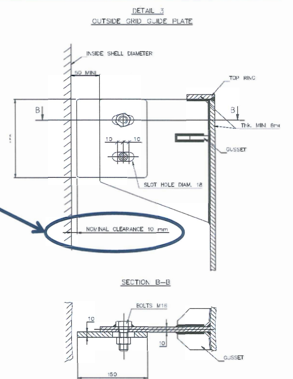
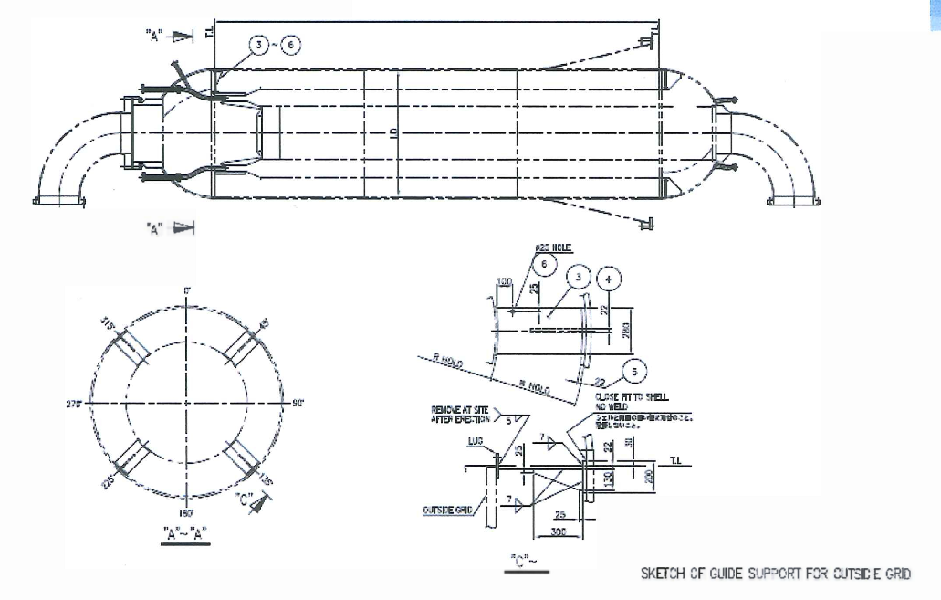
Four( 4 )-Guide Plate shall be adjusted to make nominal clearance 10mm. Temporary stiffeners and support jigs for shipping shall be removed at site.
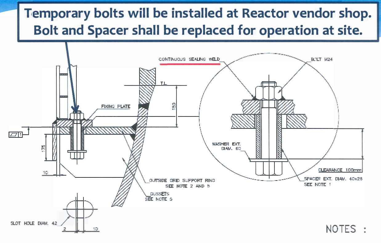
CCR Reactor Internal Parts Outside Grid Support Ring
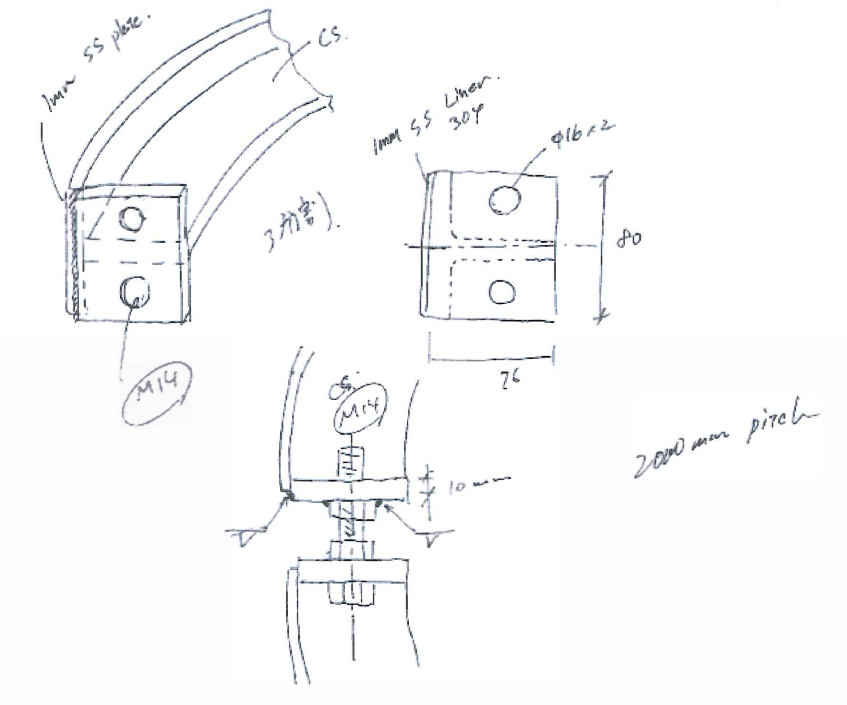
Temporary bolts will be installed at Reactor vendor shop. Bolt and Spacer shall be replaced for operation at site.
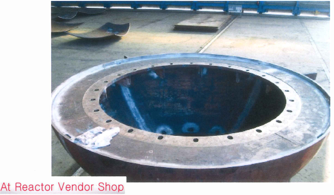
6. Complete Grid Support Ring Machining at Bottom Head
Plumbness for outside Grid.
This plumbness shall be inspected after erection of reactors at site.
Temporary shipping lugs for outside grid shall be removed after erection of reactor.
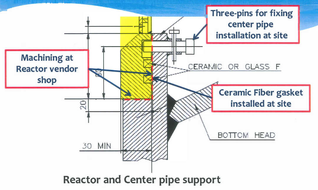
CCR Reactor Internal Centre Pipe & Sealing Rings
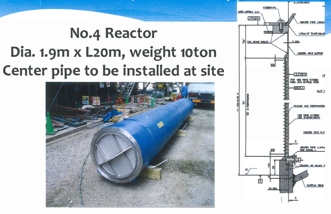
No.4 Reactor
Dia. 1.9m x L2om, weight 10 ton.
Center pipe to be installed at site
(Temporary) Lifting lugs and tailing lugs shall be supplied by internal vendor. Recommended loading procedure for center pipe shall be submitted by internal vendor.
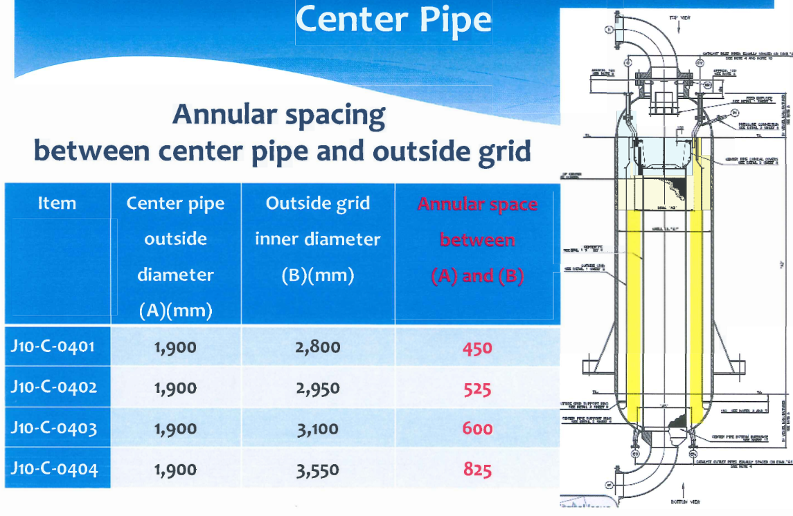
CCR Reactor Internal Parts Center Pipe
Annular spacing between center pipe and outside grid.
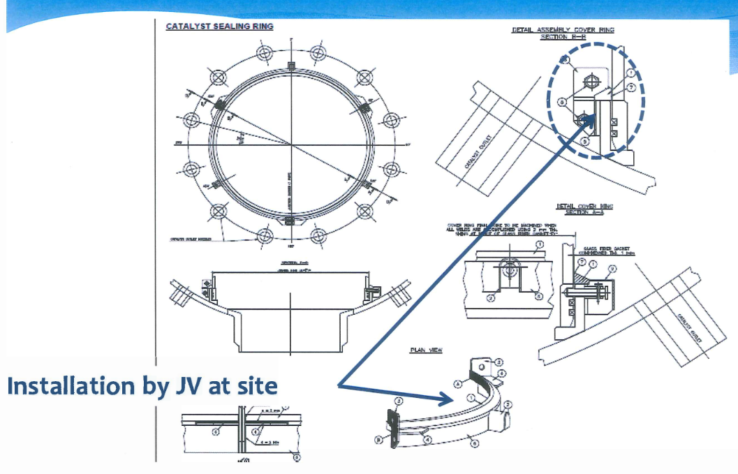
CCR Reactor Internal Parts Sealing Ring
Lowering these rings before lowing center pipe.
Loading weight for these parts to be confirmed.
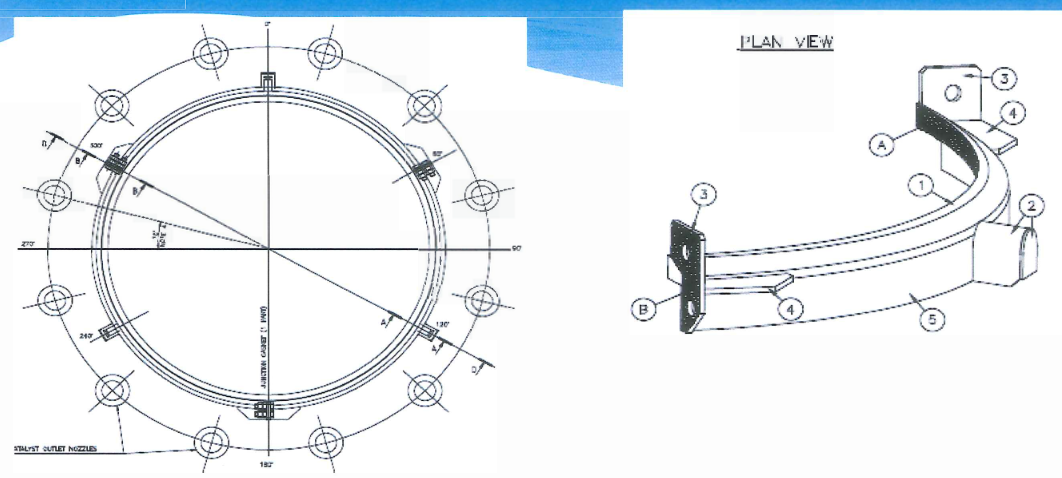
CCR Reactor Internal Parts Sealing Ring Rx No. 1
CCR Reactor Internal Conical Cover & Cover Plate
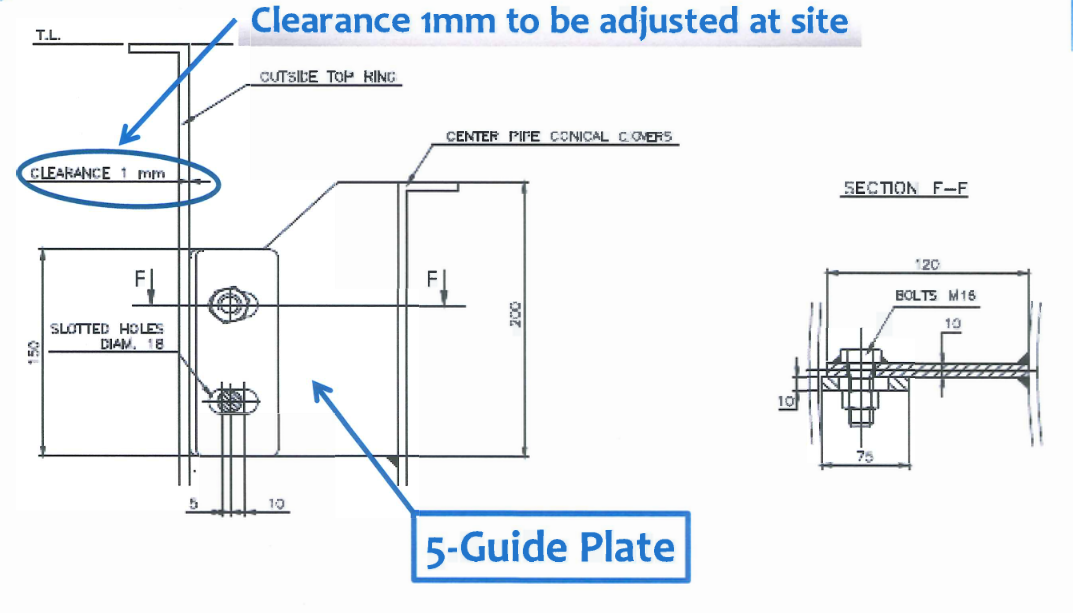
CCR Reactor Internal Parts – 5-Conical Cover Guide Plate
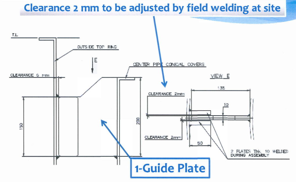
CCR Reactor Internal Parts – 1-Center pipe positioning plate
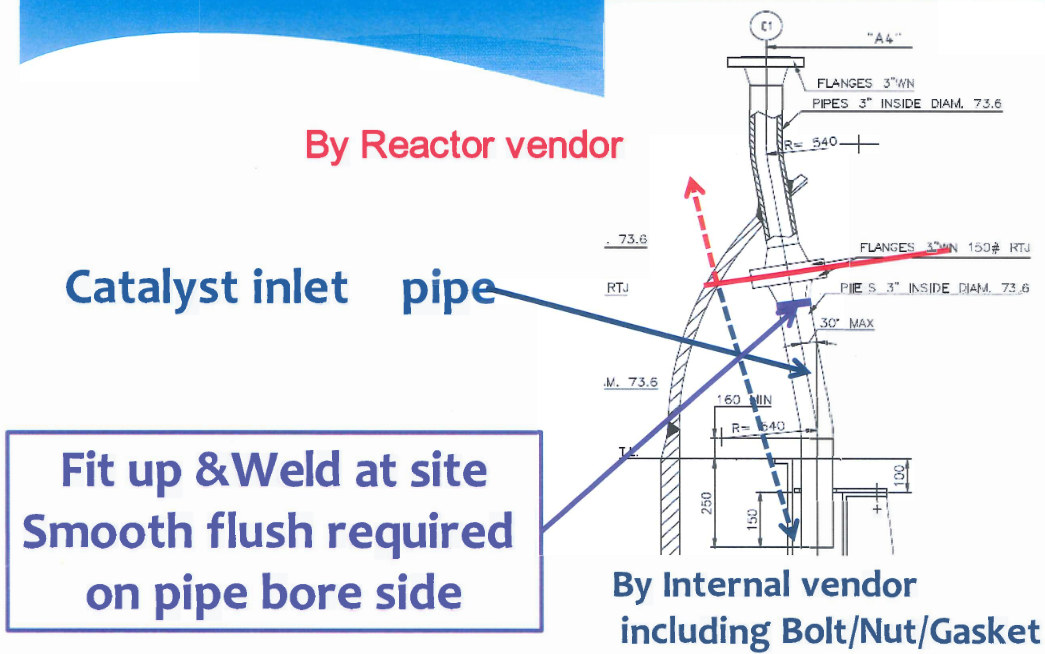
CCR Rx Internal Parts – Catalyst inlet pipe ( 12 pcs/Rx)
5.2. PIPE TO PIPE OR PIPE TO VESSEL EY FLANGE (FOR PNEUMATIC AND GRAVITY FLOW)
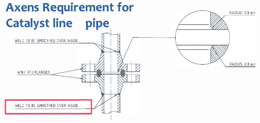
Requirement for Catalyst line pipe
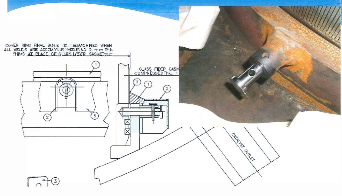
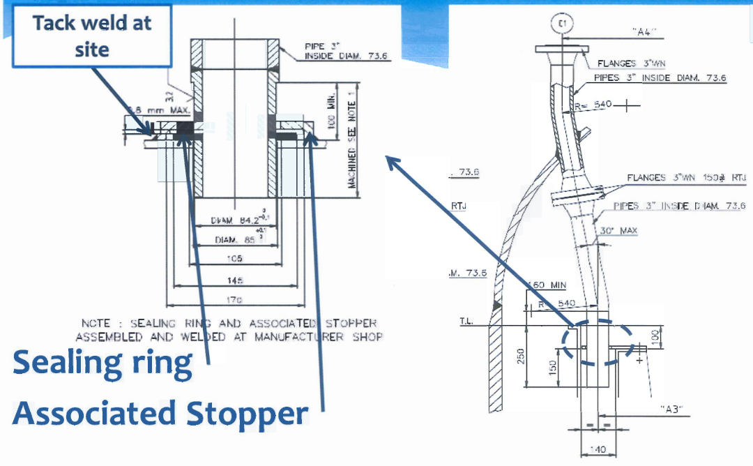
CCR Reactor Internal Parts – Sealing Ring & Associated Stopper
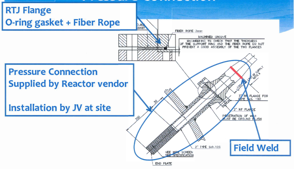
CCR Rx Internal Parts – Pressure Connection
CCR Reactor Layout
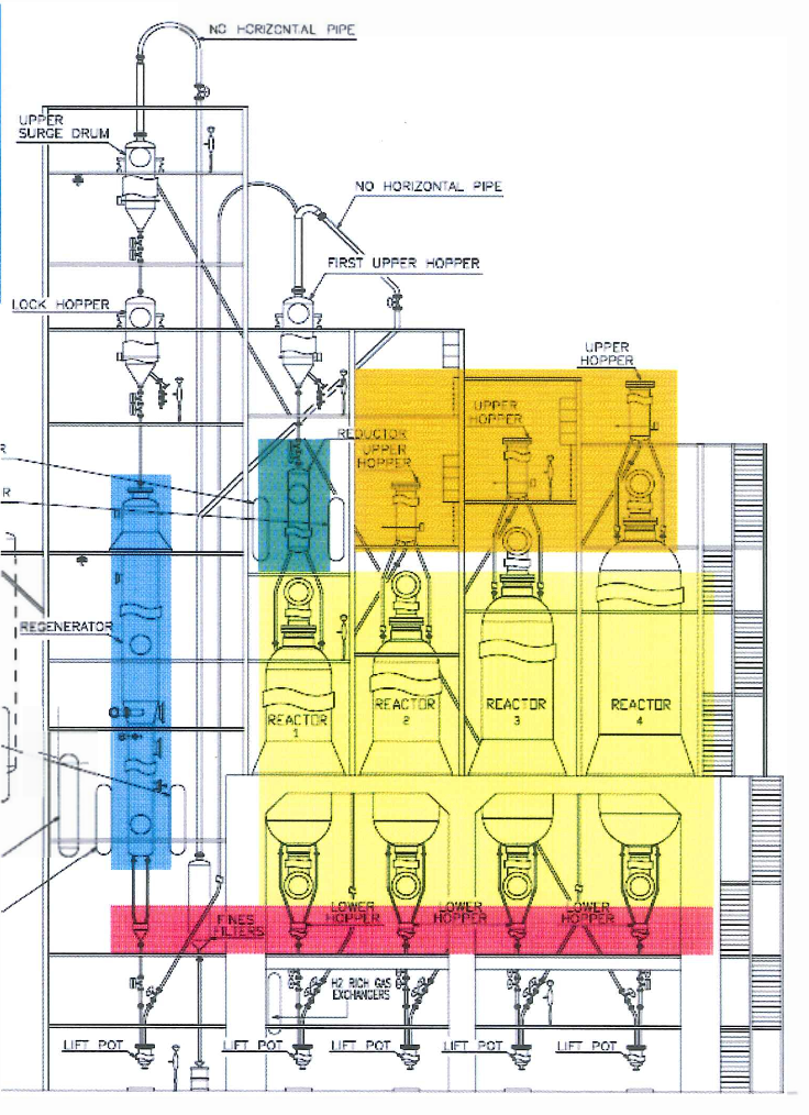
Applicable items for R-2151-101 14 ITEMS
> NO.1-4 REACTORS
> REGENERATOR
> REDUCTION CHAMBER
> NO.2-4 UPPER HOPPER
> NO.1-5 LOWER HOPPER
Plot Plan NHR/SPRITTER/CCR/ISOME
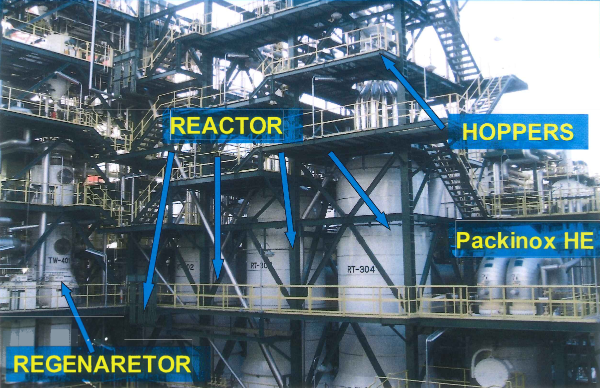
CCR Reactor & Hopper
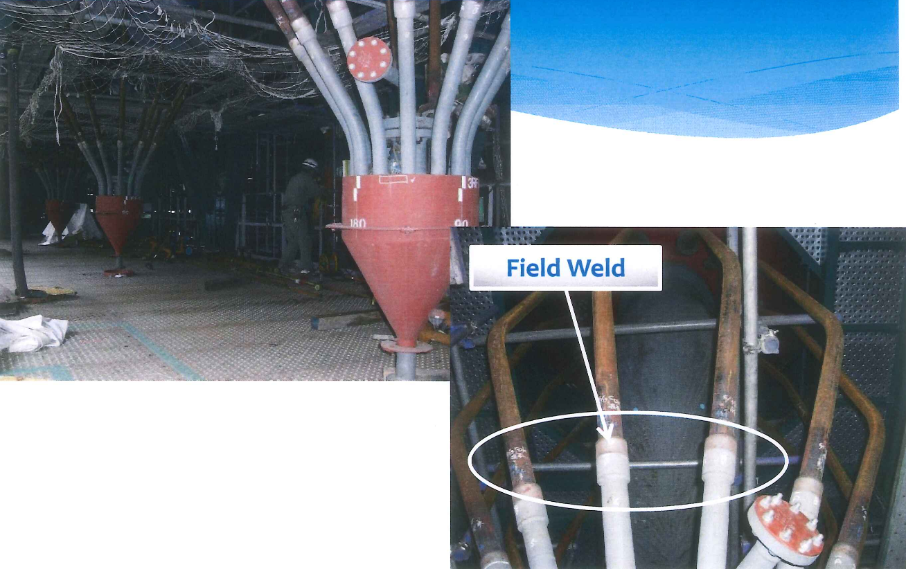
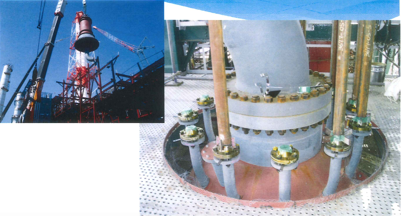
CCR Unit Piping Connection Design
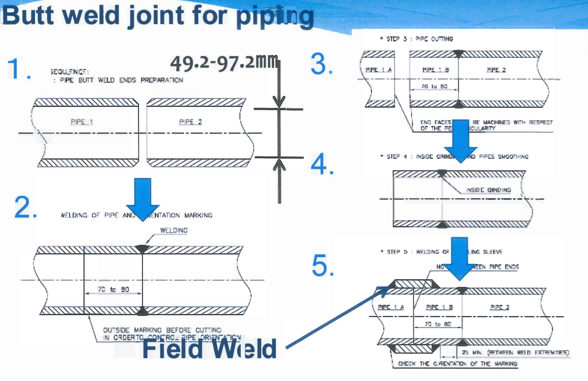
Butt Weld Joint for Piping
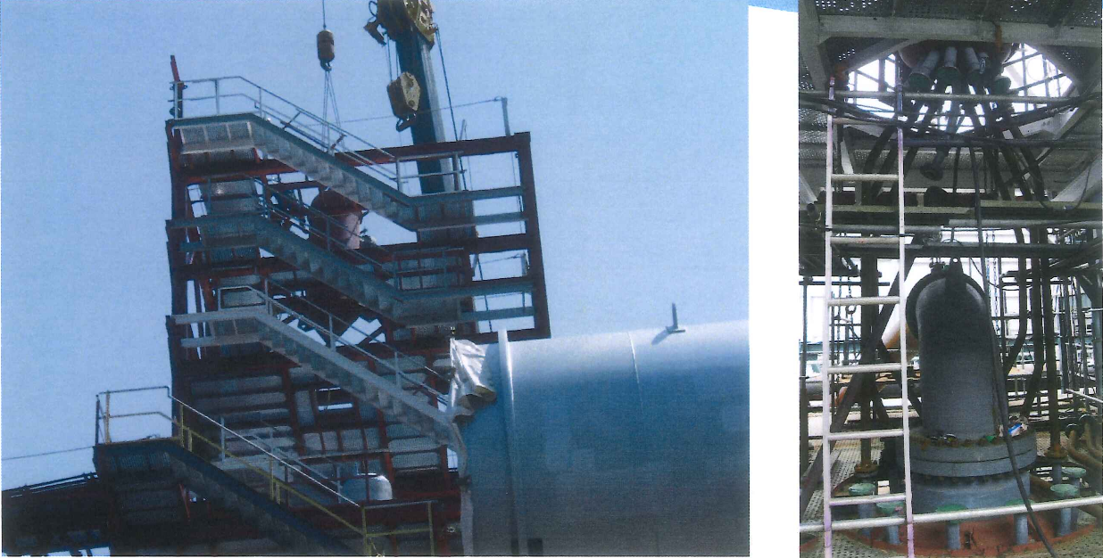
Reactor & Hopper Construction
