1. SCOPE
………………………………………………………..
2. REFERENCES
3. GENERAL
4. COLOR CODING AND MARKING OF SYSTEMS4.1 Material Color Coding
4.2 Pipe Service Markers
4.3 Submittals
……………………………………………….
4.4 Quality
Assurance
4.5 Products
4.6
Execution ………………………………………………..
4.7
Repairing of Color Code
TABLE
I
Color Code for Material Identification ……………….
II Size of Legend Letters
FIGURE
1 Application of Color Code ……………………………….
1. Scope
This specification defines the color coding requirements for positive material identification (PMI), and
markers for identifying services.
2. References
Reference is made in this specification to the following document. The latest issue, amendment, and
supplement to this document shall apply unless otherwise indicated.
American Society of Mechanical Engineers (ASME)
A13.1 Scheme for the Identification of Piping Systems
3. General
3.1 Pipe is color coded for two reasons:
a. To allow the metallurgy of each spool to be easily identified in the warehouse before erection
b. Process and utility piping can be properly and clearly identified for use by plant personnel
3.2 Each contractor, vendor and pipe spool fabricator shall identify materials as described in this
specification.
3.3 Piping components shipped individually to the jobsite shall be identified as indicated in 4.1. Material
identification shall not be required for pipe spools that have been verified by the shop and have mark piece
numbers associated with them.
3.4 Permanent color pipe service markers shall be used for process and utility services. Fabricator shall
provide service markers for spools produced. Placing the marker on the spool shall be done after piping
has been installed, coated, or insulated if required.
4. Color Coding and Marking of Systems
4.1 Material Color Coding
4.1.1 Material color coding has been developed to distinguish between various grades or specifications of
material. Table I identifies the most common grades of material used in piping systems.
4.1.2 Color markings are assigned on the basis of nominal chemical compositions.
4.1.3 Location of marking shall be as follows:
a. Pipe shall be marked with, for example, paint, dye, or tapes for its full length
b. Flanges shall be banded on the back of the flange at the intersection of the back face and the
hub
c. Fittings shall be striped from bevel to bevel
d. Miscellaneous material shall be color marked so as to provide proper identity
e. The paint shall not cover welded surfaces, heat marks, or any other identification
4.1.4 See Figure 1 for typical markings.
4.2 Pipe Service Markers
4.2.1 Permanent color pipe service markers shall be used for all process and utility piping systems within
the plant.
4.2.2 Piping systems shall include utility pipes of any kind and, in addition, fittings, valves, and pipe
coverings. Piping systems shall be painted a neutral background color, for example aluminum or gray,
which shall not detract from the high visibility of the colors and lettering of the service markers.
4.2.3 Permanent color markers for piping systems shall be placed at the battery limit and at vertical risers
at utility stations. Service markers shall be applied close to valves or flanges, and adjacent to changes in
direction, branches, and where pipes pass over or through walls, floors, fences, or roads, and on straight
pipe runs, sufficient for identification.
4.2.4 A service marker in English shall be used as the primary and explicit means of identification for the
contents of all aboveground piping. Positive identification of the contents of a piping system shall be by
lettered legend giving the name of the contents in full or abbreviated form. Arrows shall be used to indicate
direction of flow. Additional details, for example temperature or pressure, shall be added as necessary to
highlight the degree of hazard.
4.2.5 Shutdown, emergency, or car-sealed valves shall be labeled with P&ID and valve numbers and any
descriptive labeling needed to permit easy identification. Firewater system sectionalizing block valves shall
be identified by their firewater system identification number.
4.2.6 Contrast shall be provided between color field and legend for readability. Letters shall be in Sans Serif
Gothic Bold font. See Table II for specific sizes. For identification of materials in pipes of less than
3
/4 inch (19 mm) in diameter, and for valve and fitting identification, the use of a permanently legible tag is
recommended. The size of the service marker letters shall not be less than 13 mm, nor greater than
89 mm, varying in size depending on the outside diameter of the pipe.
4.2.7 For piping 2 inch NPS and smaller running between equipment, where the total length is less than
15 m, no service marking shall be necessary. For piping on pipe racks, service marking shall be oriented in
a way that it is visible from grade level and from any nearby platform.
4.2.8 Unless otherwise specified by SABIC, the color of the service marker letters shall be black or white,
whichever provides the greater contrast to the background color.
4.2.9 Pipe markings shall be clearly visible. Where pipe lines are located above or below the normal line of
vision, the lettering shall be placed below or above the horizontal centerline of the pipe.
4.3 Submittals
Contractors supplying materials that might be damaged by the application of any part of this specification
should submit alternative methods of marking before proceeding.
4.4 Quality Assurance
SABIC will examine and inspect the final products, to ensure conformance with this specification.
4.5 Products
Marking materials for stainless steel and nickel alloy piping shall not contain any harmful substances, for
example chlorides, fluorides, sulfur, and low melting point metals.
4.6 Execution
4.6.1 Surface Preparation. Surfaces to be color coded or marked shall be free from oil, grease, dirt, and
other surface contaminants that might be detrimental to the adhesion of the paint used for color coding and
marking.
4.6.2 Application
a. Whenever color coding or marking paint is to be applied to a primed surface, the primer shall be
dried completely before the color coding or marking paint is applied.
b. Color coding, marking, and identification paint shall be applied to dry, clean surfaces in
accordance with manufacturer’s instructions.
c. Unless otherwise recommended by the manufacturer, color coding and marking shall not be
undertaken when the ambient temperature is less than 10 °C (50 °F), or the relative humidity is more
than 90 percent.
d. Color coding and marking paint shall be applied in 1 coat.
4.7 Repairing of Color Code
Marshaling yards or receiving yards shall maintain the capability to perform touch-ups for repair of color
coding.
Table I
Color Code for Material Identification
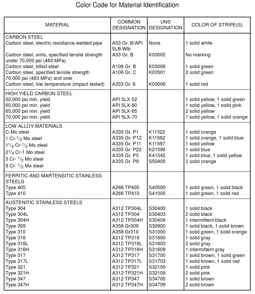
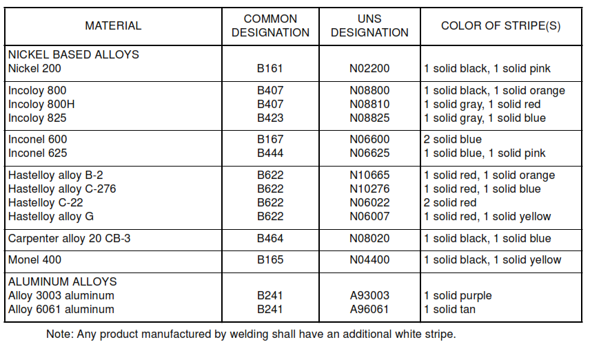
Table II
Size of Legend Letters
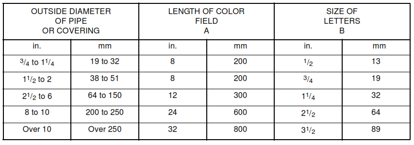
Figure 1
Application of Color Code
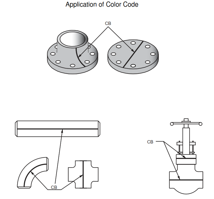
- Do not apply paint to gasket seating areas or weld bevel areas.
- Paint shall not cover welding surfaces.