This article is about Commissioning of High Voltage Circuit Breakers, Contactors, Switches and Control Equipment and Electrical Protective Device Verification Reports used in commissioning phase of electrical projects.
This commissioning procedure and technical specification outline the necessary procedures for the proper commissioning and maintenance of high voltage circuit breakers, contactors, switches, and control systems.
The scope of this commissioning technical specification encompasses a range of activities, including visual and mechanical inspections, as well as electrical and functional testing of high voltage circuit breakers, contactors, switches, and their associated control systems. These procedures are crucial to ensuring the safe and effective operation of high voltage equipment in various industrial applications.
Electrical Commissioning and Start-up Checklist
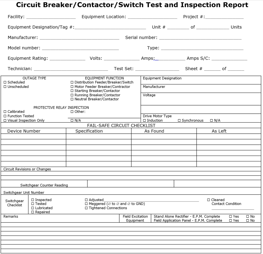
High Voltage Circuit Breakers, Contactors and Switches Nameplate Data
Date:___________
Facility:__________ Equipment Location:______________________ Project #: _____________
Equipment Designation:_________________________ Unit # _______ of _______ Units
Manufacturer:___________________ Serial number:___________________________
Model number:_____________________ Type:_________________________________
Equipment Rating:_________ Volts:____________ Amps:__________ Amps S/C:___________
Technician:______________________________ Sheet # ____ of ____
Visual and Mechanical Inspection for all Equipment
- Initial Inspection: Upon receipt of the equipment, perform an initial inspection to identify any physical damage resulting from shipping. In the event of damage, report incidents following the shipper’s instructions.
- Verification of Nameplate Information: Compare the equipment’s nameplate information with the latest single line diagram and equipment specifications to ensure consistency and accuracy.
- Cell Fit and Alignment: Ensure proper cell fit and alignment of components, addressing any misalignment issues as needed.
- Mechanical Operation Check: Execute all mechanical operation checks on both the breaker and its operating mechanism, adhering to the manufacturer’s instruction literature.
- Preventative Maintenance: Conduct routine preventative maintenance procedures as per the manufacturer’s instruction literature.
- Contact Verification: Verify the contact wipe, alignment, spacing, and other parameters critical to satisfactory operation.
- Charging Mechanism and Interlocks: Examine the operation of the charging mechanism, cutoff switches, and auxiliary relay and/or interlocks. Additional tasks may apply to specific types of equipment.
- Cleaning and Lubrication: After completing the above tasks, clean and lubricate the primary and secondary contacts with approved lubricant.
- Insulation Resistance Test: Perform an insulation resistance test (Megger) and function test using a remote test stand. If the remote test stand is unavailable, use the test position.
- Interlock Verification: Verify the proper and complete operation of all mechanical and electrical interlocks, including any key-type systems.
This comprehensive visual and mechanical inspection ensures the equipment’s integrity, alignment, and functionality, contributing to safe and reliable operation in industrial settings.
Operational and Electrical Testing for all Equipment
- Field Device Checks:
- Perform a physical wire check and electrically function check on each field device to ensure it activates the appropriate shutdown relay or starter.
- Protective Relay Calibration:
- Calibrate all protective relays according to the latest International Electrical Testing Association (NETA) Acceptance Testing Specification.
- Follow Section for Electromechanical Relays and Section below for Microprocessor-based relays, while also considering manufacturer recommendations.
- Ensure that the relay software revision and setting file software revision match.
- Utilize Electrical Engineering job-specific relay settings and record the calibration results.
- Send calibration files to Electrical Engineering for reference.
- Fail-Safe and Protective Relay Verification:
- Verify that each fail-safe and/or protective relay correctly trips the breaker or starter and record the results.
- Time Delay Relay Check:
- Set, check, and verify all time delay relays to ensure they operate with proper timing.
- Contact Resistance Measurement:
- Perform contact resistance measurements with the breaker/switch in the closed position using a digital low resistance ohmmeter (Ductor).
- Consult the manufacturer’s instruction literature for the maximum allowable value; if unspecified, use 300 micro-ohms (0.0003 ohms).
- Calculate the average of three readings for each phase, ensuring that the values fall within 10% of each other. Record the results.
- Insulation Resistance Test:
- Perform an insulation resistance (Megger) test on each pole with the breaker/contactor/switch closed.
- Test phase-to-phase and phase-to-ground for one minute and record the results.
- Jumper Log:
- Maintain a jumper log during the start-up period.
- After control circuit testing, check for any “test” jumpers that may have been inadvertently left on.
Thorough operational and electrical testing ensures the reliable functionality of equipment and associated relays, contributing to safe and efficient industrial operations.
High Voltage Switch Checks
- Blade Alignment and Arc Interrupter Operation:
- Inspect the blade alignment and verify the operation of the arc interrupter. Consult the manufacturer’s instruction literature for guidance on this procedure.
- Clearances Inspection:
- Examine clearances in the switch to ensure they meet safety standards. Reference the manufacturer’s instruction literature for specific clearance requirements.
- Fuse and Linkage Inspection:
- Check the fuse, linkage, and element for proper holder and current rating. Ensure that these components are suitable for their intended purpose.
- Operational Verification:
- Operate the switch 2 to 3 times to verify its proper operation. Confirm that the switch functions smoothly and consistently.
- Line Side Termination Verification:
- Ensure that the line side of the switch is correctly terminated on the stationary contact of the switch. If this is not the case, consult Electrical Engineering for guidance on the necessary corrective actions.
- Spare Fuses and Fuse Puller Check:
- Verify that spare fuses are of the correct rating and that a fuse puller is provided for safe replacement procedures.
Performing these high voltage switch checks helps ensure the reliability and safety of the switch’s operation and associated components.
Vacuum Circuit Breaker/Contactor Checks
- High Potential Test on Interrupters:
- Perform a high potential test on each interrupter for a duration of one (1) minute. Exercise caution and adhere to the manufacturer’s instruction literature, especially regarding X-radiation hazards and specified voltage levels. Record the test results.
- Tolerance Verification:
- Verify the tolerances for erosion, contact travel, and overtravel in accordance with the manufacturer’s instruction literature. Ensure that these parameters align with the recommended specifications.
- Initial Contact Wear Position Indicator:
- Check the initial contact wear position indicator to ensure it is functioning correctly. This indicator provides valuable information about the condition of the contacts.
- Manufacturer’s Instruction Literature:
- Refer to the manufacturer’s instruction literature, particularly the sections related to installation and maintenance. Follow the recommended procedures and checks as outlined in the literature.
Performing these checks on vacuum circuit breakers/contactors helps ensure their proper functioning, adherence to safety standards, and compliance with manufacturer specifications.
SF6 Circuit Breakers Checks
- Manufacturer’s Instruction Literature:
- Refer to the manufacturer’s instruction literature, specifically the sections related to installation and maintenance. Follow the procedures and checks recommended by the manufacturer for SF6 circuit breakers.
- SF6 Low Pressure Alarm:
- Verify the SF6 low pressure alarm in accordance with the manufacturer’s published data. This alarm is crucial for monitoring the pressure of the SF6 gas inside the circuit breaker and ensuring its proper functioning.
By adhering to the manufacturer’s guidelines and verifying the low-pressure alarm, you can maintain the reliability and safety of SF6 circuit breakers.
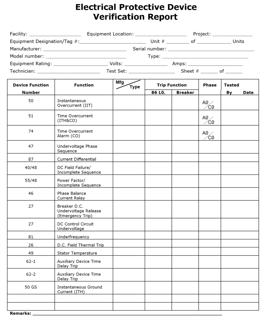
Electrical Protective Device Verification Report
Related Articles
Electrical Equipment Commissioning
Electrical Work in Plants, Commercial Buildings and Refineries.