This article is about specification and requirements for concrete and foundation for any civil projects. Contractor shall submit proposed concrete design mix to client for review and approval as per specifications.
Contractor shall propose their preferred notified body and third party inspection organization with the bid. Company representative shall confirm that the contractor has his independent test laboratory arranged to support the construction schedule.
Concrete and Foundations Specification | Concrete Placement Requirements
Soil density tests on all major foundations.
Large foundations should have all quadrants tested. Typical description of major foundations shall include foundations for cold boxes, compressors, PSA’s, cooling towers, reformers etc., structures that support them and the interconnects are also important. Some sidewalks, ramps, and other equipment items that do not have a large bearing load are not considered major unless specified by the Civil Engineer.
- Verify concrete slump is within specified tolerance prior to pour. If consistency or workability of concrete has changed additional slump tests shall be made. Slump may vary as defined in specification 28-4ACS640102.
- Verify air entrainment is 5% to 7%, unless otherwise noted on drawings or specified in the approved design mix. If concrete slump or air content exceeds specifications, do not pour. Send concrete truck back to batch plant for corrections. If minor corrections are needed, make sure subsequent trucks are acceptable.
- Obtain concrete cylinder samples. Minimum of one set of four per 100 CY per day, or for each major foundation. Test laboratory to break one cylinder at seven days, two at 28 days, hold one cylinder, and issue reports. The hold cylinder will be broken at 56 days in the event that the 28-day cylinders do not pass the mix design strength. In the event any of the test cylinders do not pass the minimum design strength requirements, the structural design engineer must be notified. Reports must be initialed to indicate the acceptance of the results or an NCR must be issued if the results are out of limits. Seven-day break should be at about 85% of design strength for concrete using type I cement.
- Additional cylinders may be requested: 1) if concrete strength needs to be verified earlier to place a load on it, 2) forms are to be removed prior to recommended time as defined in specification 28-4ACS640102, or 3) if there is concern that the mix is a potentially unacceptable. Log the cylinders in a concrete summary. Make sure laboratory reports clearly indicate unique identifier (e.g., equipment number or foundation number) and foundation description. Cylinder samples to remain onsite for 24-hour in accordance with ASTM C31.
- When onsite the test laboratory representative to review concrete truck delivery tickets for quantity of load, time and amount of water added at batch plant, and general compliance to the design mix criteria. Check concrete temperature to verify acceptability of mix.
- Concrete shall not be used if it has been more than 90 minutes since the addition of water. This shall be reduced to 60 minutes in hot weather. Check concrete temperature to verify acceptability of mix.
Contractor Representative is to check accuracy of centerline and benchmark elevations used to establish major foundations prior to any pours.
All foundation forms to be checked from the control lines and benchmarks for proper length, width, thickness, and elevations prior to pour.
Review that forms are adequately braced. For critical foundations, (tank foundations, elevated slabs, etc.), the contractor’s calculations should be submitted for a design approval. Contractor shall provide calculations to support the rate of concrete placement for tall vertical pours (e.g. columns, walls, etc). Calculations shall be based on the ambient temperature expected at time of the pour.
Reinforcing Steel Inspection:
- Visually verify proper grade of material, typically Grade 60. Additionally, verify mill certificates for each batch of reinforcing material.
- Reinforcement steel placement drawings for major foundations may require review and approval from Civil Design. Per Engineering procedures foundations that require reinforcing steel submittal are documented on the particular foundation drawing. Verify requirements with project designer…
- Verify splice overlap is correct as per contract drawings or contact Civil Engineering.
- Reinforcing steel shall be tied firmly and securely braced so there is no movement during concrete placement.
- Reinforcing steel that requires modification in the field shall be cold bent. No hot bending allowed.
- No welding of reinforcing steel is allowed.
- When using a woven wire fabric (W.W.F.), verify proper grade material, size, mesh, and proper depth into the concrete as indicated on the drawing.
- The use of concrete bricks for side form or ground clearance is acceptable. Refer to specification 28-4ACS640101 for brick requirements.
- Check for correct concrete cover on reinforcing steel, and adequate clearance between reinforcing steel and the formwork and the ground.
- Reinforcing Steel needs to be free of mud and excessive rust.
- Tie wire shall be black annealed wire number 16 gauge or heavier.
- Support chairs for reinforcing steel mats shall have plastic covered feet.
Anchor Rods/ Embeds/ Conduit/ Grounding:
- Verify correct grade of material used for anchor rods. Contractor to provide material certifications.
- Check anchor rod diameter, overall length, length of tail, and thread length for conformance to Anchor Bolt Schedule.
- Verify that anchor rods and embeds are correctly located in foundation. Elevations and projections correct? Compare placement drawings against the latest vendor prints, if available to confirm anchor rod layout and projection.
- Use diagonal check on anchor bolts to verify that they are square, for right angle patterns.
- Use anchor bolt template when provided by equipment vendor.
- Verify that welding of plates or nuts to anchor bolt and embeds is in strict accordance with welding details shown on the anchor bolt schedule and fabrication details shown on drawing. If tack welds are shown, this is required – NOT solid weld. Check size and placement of welds.
- Anchor rods and embeds should be properly secured and supported so there is no movement. Check vertical alignment and location during the placement of concrete.
- Ensure expansion sleeves are set at proper elevation and sealed to prevent concrete from entering sleeve.
- Anchor bolt sleeves shall be capped to prevent entrance of concrete and grout into the sleeve. Anchor bolts for machinery must be able to stretch along there full length.
- Anchor bolts, embeds, and conduit should not be braced or supported from the reinforcing steel due to the movement of the rebar during concrete placement. Where necessary for large foundations, precautions should be taken to prevent movement during pouring of critical embeds.
- Ensure all UFER and conduit grounds are installed prior to placing concrete. Perform hammer test in accordance with specification 620.304. Locate the equipment ground pigtail at a location close to where the ground will be attached. This will minimize the length of conduit runs on the top of the foundation. ”The Ufer ground is an electrical earth grounding method developed during World War II. It uses a concrete-encased electrode to improve grounding in dry areas. The technique is used in construction of concrete foundations. Wikipedia”
- Ensure all conduits and drains are properly located, adequately braced, capped, and joints taped and sealed to prevent concrete from entering. Unprotected conduit elbows and stub ups shall be rigid galvanized conduit.
- Clean up anchor bolts immediately after pour. Protect threads and nuts with tape or plastic caps until the mechanical contractor arrives on site.
- When applicable, ensure local municipal inspections are performed on reinforcing steel, anchor bolt, and embed placement prior to pour.
Concrete Placement – General:
-
- Inside of forms coated with releasing agent.
- All debris inside formwork must be removed.
- Ensure all disturbed areas are compacted to 95% of the maximum dry density as determined by the modified proctor, or as specified by the drawings.
- Remove any freestanding water prior to concrete placement. If soil conditions are dry ensure sub-grade surface is thoroughly saturated prior to concrete placement.
- All concrete to be placed monolithically unless specified otherwise.
- Proper vibration – especially on walls, compressor column, around tank embeds, etc. is required to eliminate any voids or air pockets. However, do not over vibrate as it causes aggregate to separate and settle. Vibrators shall not be used to move concrete within foundations. Concrete shall be placed using chutes, buckets, hoses, tremies, shovels or concrete rakes.
- On tall pours such as columns or walls, contractor or form supplier must provide rate of pour per elevation. This is required to ensure that forms are not displaced.
- Ensure contraction, expansion, and construction joints, and water stops are installed in accordance with the contract drawings.
- When placing new concrete on old concrete the old concrete must be thoroughly cleaned and chipped to expose old aggregate and remove laitance. Surface must either be thoroughly wet down or a bonding agent applied to the surface prior concrete placement. Reinforcing steel must be clean –free of old concrete, mill scale, oil, wood chips, etc. — prior to placement of subsequent concrete.
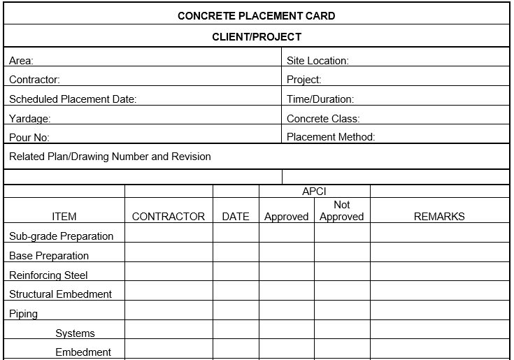
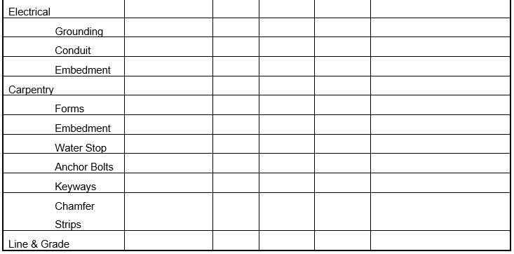
- Prior to placing concrete have contractor complete concrete placement card.
Concrete Placement from Elevated Points:
-
- Formwork for elevated decks shall be designed with a 4 to 1 safety factor in accordance with OSHA requirements for work surfaces.
- Tremie, elephant trunk or pumping shall be utilized to prevent segregation. Pay particular attention to columns for compressors or walls.
- Vibrator shall be utilized in an approved manner by experienced craftsmen. Do not over-vibrate or move concrete with vibrator.
- No free fall greater than 5’ is permitted.
Cold or Hot Weather Precautions Being Applied in Accordance with American Concrete Institute Standards:
- Hot Weather – Heat speeds up the chemical reaction (hydration) that occurs with concrete placement. Hot weather precautions are required when:
- Air temperature is 90°F or higher regardless of humidity.
- Air temperature is 80° to 89°F and relative humidity is 60%, or less.
- Air temperature is 70° to 79°F and relative humidity is 40%, or less.
- Utilize: moist coverings, night pours, cooled aggregate, mist sprays, reflective curing compounds, retarding admixtures, specify low temperature delivered, sunshades and windbreaks, avoid excessive mixing, reduce time between mixing and placing, continuous cure with water, protect drying surfaces, and spray exterior of forms with water.
- Cold Weather- cold slows down the chemical reaction that occurs with concrete placement. Cold weather precautions are required when the ambient temperature drops below 45°F. Utilize daytime pours, temporary heat or steam, accelerating admixtures, specify higher temperature delivered, use heated enclosures and windbreaks, keep placement equipment and forms warm, avoid water curing, use curing compounds, protect drying surfaces with insulation blankets that have the proper insulation value, and delay stripping forms for as long as possible. Surface temperature must be maintained at 50°F or higher for five consecutive days after pouring for proper cure. Allowing concrete to freeze will cause strength loss.
Additives – Review that specified additives are being used. Do not use curing compound on construction joints for subsequent pours unless approved by the designer.
Do not remove forms from green concrete. Special consideration should be given to load bearing concrete such as elevated slabs, etc. Seek advice from the designer or the guidelines in 28-4ACS640102 if unsure about appropriate curing times. A minimum of four days of cure time is needed unless a variance is approved by the Civil Engineer, based on the early concrete test cylinder results. Patching tie-marks shall be completed when forms are removed.
Before and immediately after placing of concrete, inspect and verify that size of foundation, and locations and projections of critical anchor bolts are correct to drawings.
Use the first major placed foundation as the bench mark (center line and elevation) for subsequent foundation location or layout of engineered systems. Use the centerline and elevation of the major foundation as the bench mark for associated foundations in the same area.
As-built received. To include final survey of centerlines, elevations of major foundations, and yard areas.
Concrete and Foundations: Flat Bottom Tanks
- Foundations:
- Piles or caissons – locations are as-built within the required tolerances. If out of tolerance contact Civil Engineer since the tank foundation reinforcing steel may need to be redesigned.
- Soil compaction and proper density tests performed if not on piles or caissons.
- Formwork – inspect for proper location, orientation, size, depth and elevation and adequate bracing.
- Reinforcing Steel – verify reinforcing steel for proper diameter, grade material, and spacing, clearance to forms, grounding, and top of concrete elevation before placement.
- Heating element conduit need to be installed with couplings and a mandrel was passed through conduits after concrete placement to verify conduit did not compress during placement.
- Design Mix – approved by Civil Engineer.
- Curing – method, material, approved and applied per manufacturers instructions.
- Concrete – air, slump, cylinders and temperature readings taken during concrete placement. Verify concrete cylinder test results are acceptable.
Anchor rods or Anchor Straps – In Foundations
-
- Check anchors against approved drawings prior to installation. Verify proper thickness, welding, proper threading, details, length and width.
- Check orientation before placing and location after installation. Ensure bolts, sleeves and straps are plumb.
- Check for proper depth into concrete, extension and top of anchor.
- On anchor sleeves, cap sleeve off to prevent concrete or foreign matter entering sleeve.
- On anchor rod installation, ensure rod is screwed the full thread depth into the anchor plate.
- Anchor straps and plates – ensure that concrete is properly vibrated around plates, particularly on the underside of the plate. Incomplete consolidation and voids in concrete at anchors are not acceptable.
- Anchor strap splices require 100% radiograph examination.
Foundation Inspection – After Concrete Placement
-
- Flatness of top surface within tolerance specified on drawing.
- Anchor bolts or straps plumb. Projection above concrete correct.
- Inspect anchor layout again for drawing conformance.
- Anchor sleeves or straps solid in concrete.
- Foundation acceptance by tank erector. After tank erector inspects foundation, obtain acceptance in writing prior to allowing tank erection to begin.
QC Documentation
- Some tests require contractor sourced testing company. The construction home office shall write a purchase order with assistance from the field, to ensure insurance requirements are met. Include in the QC, qualifying certifications of the lab and of the technicians performing work. Include the concrete break equipment certification and the air entrainment equipment certification.
- Approved design mix.
- Critical form calculations, as specified by Civil Engineering.
- Mill test certificates for each heat number of reinforcing steel delivered.
- Reinforcing Steel drawing approvals for foundations specified by Civil Engineering.
- Anchor rod mill certifications.
- Signed concrete placement cards.
- Independent concrete testing laboratory’s daily reports.
- Copies of all concrete tickets for foundations that did not reach appropriate strength requirements
- Concrete cylinder test results.
- As-built information and final survey.
- Below is example or guide for pour card QC records.