1 Scope – 1.1 This article recommends power-grounding practices for various types of computers, programmable controllers, distributed control systems, peripherals; interconnect systems, and other such associated equipment. Also included are typical arrangements to assist in the design of a grounding system for computer and control equipment located in a non-hazardous area.
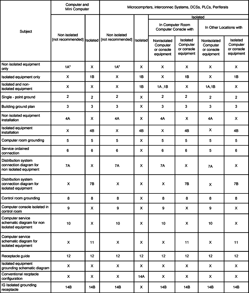
1.2 Table l provides an application guide and an index to applicable sections and figures of this standard.
1.3 An overview of power-grounding requirements is provided by identifying design factors, for example:
- Low-impedance grounding to earth.
- Single-point grounding.
- Isolated and non-isolated equipment.
- Power distribution.
2 Control System Grounding Code References
Standards and Code References is made in this article to the following documents.
Bonding and Grounding.
Control Systems Design Criteria.
National Electrical Manufacturers Association (NEMA)
WD 1 General Color Requirements for Wiring Devices.
National Fire Protection Association (NFPA)
70—National Electrical Code (NEC)
3 Control System Grounding Guidelines General
3.1 Grounding systems shall ensure the safety of personnel from shock hazards NEC Article 250.
3.2 Improper grounding can result in conditions that lead to computer problems.
These conditions include:
3.2.1 Static electricity discharging through the computer electronics
3.2.2 Circulating currents through system common (“common-mode noise” and “ground loops”)
3.2.3 Floating or high-resistance type grounds.
3.2.4 For general guidelines of instrument grounding systems refer to Bonding and Grounding & Installation of Grounding and Bonding Conductors.
3.3 All equipment connected to the computer system shall be analyzed to define its grounding type (isolation scheme—refer to Section following) and grounding
requirements.
3.4 This standard provides grounding schemes consistent with computer vendor requirements; however, vendor‘s grounding instructions must be obtained and reviewed prior to selecting and designing a grounding system.
3.5 Computer grounding systems require periodic inspection and testing. Appropriate maintenance personnel shall review design philosophy as soon as possible to ensure compatibility with existing or proposed inspection and testing procedures.
3.6 Computer equipment is frequently installed in rooms with special flooring. This flooring may be:
3.6.1 Raised with continuous bolted stringers providing electrical continuity between pedestals.
3.6.2 Raised with no continuous stringer.
3.6.3 Special flooring with grounding conductors embedded in the flooring.
3.6.4 Each of these systems requires its own grounding considerations as recommended by the flooring manufacturer. Generally, grounding of the above is as follows:
Raised with stringer—one 16 mm2 (No. 6 AWG) wire from building steel to a single pedestal every 0.9 M2.
Raised without stringers—tie each pedestal with 6 mm2 (No. 10 AWG) wire to central point every 0.9 M2 and then connect with 16 mm2 (No. 6 AWG) wire to building steel. Special flooring—per vendor‘s instruction.
3.7 The grounding designs recommended in this standard might not be applicable to very large mainframe computer installations. The high switching speeds cause
high frequencies to be reflected in the grounding current. This fact, combined with the long ground conductor lengths found in large rooms, results in high impedance to ground and makes for an unacceptable grounding installation.
When this situation occurs, a grounded grid is used to provide many paths to ground, thus eliminating the problem resulting from high frequencies and long ground conductors. A raised floor with electrically continuous stringers is an effective way of implementing a single-reference grid. This allows the immediate advantage of distributed capacitive coupling of high-frequency noise to ground and the future advantage of changing from the recommended approach shown herein to a grounded grid scheme made necessary by future technological computer developments.
3.8 Power supply for computer type equipment shall be as follows:
3.8.1 Uninterrupted AC power (230 Vac)
This power shall be used for:
Instruments.
DCS consoles and cabinets.
Alarm and shutdown systems.
Process computer system and host computers.
Analyzers.
Sequencing and interlock PLC‘s.
Manually selectable 127/230 Vac power supply or equipment shall not be used.
3.8.2 Miscellaneous Power (230 Vac)
This power shall be used for all non-critical loads in the control system. Manually selectable 127/230 Vac power supply or equipment shall not be used.
3.8.3 Uninterrupted DC Power (DC 24V)
This power shall be supplied for instrument relays, solenoid valves and other equipment, which are part of the Safety Interlock Systems (SIS).
3.9 Power Distribution
3.9.1 The electric power distribution system for instruments shall include an instrument power distribution board in the auxiliary rack room. A circuit protector shall be furnished for each branch circuit.
3.9.2 Particular care shall be given to the selectivity of protection devices against over-currents, so that in the case of a short circuit, the other branches will not be affected.
3.9.3 Branch circuit design will ensure that circuits and loops will be protected in related groups to meet process fail safe requirements.
3.9.4 Branch circuit assignments to transducers and self-powered transmitters in control loops shall be made to ensure fail-safe design.
3.9.5 The current loading of branch circuits shall be less than 70 percent of the circuit breaker rating. The voltage drop of 2-wire circuit from the breaker panel to the farthest device shall be less than 3 percent of the nominal voltage. Splicing of the neutral wire is prohibited except in a junction box.
3.9.6 The neutral wire connected to a device shall always be the one assigned to the breaker, which serves that device and never one from another source.
3.9.7 Refer Control Systems Design Criteria for spare breakers requirements in PDP (Power Distribution Panels).
4 Mainframes, Minicomputers, and Microcomputers
4.1 All new buildings housing computer facilities are to be provided with a total structure resistance to ground of one ohm or less.
4.2 All existing buildings housing new computer installations shall have their structure grounding impedance lowered to one ohm or less.
4.3 All existing computer installations shall be checked annually to ensure that no difference in potential exists between the building ground (NEC 250) and computer ground systems. If a potential difference does exist, ensure that the ground systems are tied together as described in Section 4.9.
4.4 Many existing computer installations are grounded using conventional methods. Factors to be considered to determine if the existing grounding system should be
upgraded include the following:
4.4.1 Safety
- Computer system performance record
- Future computer systems
- Economics
- Future changes to surrounding facilities could result in a ”noisy” conventional ground system: for example, a non-computer related project providing silicon-controlled rectifier (SCR) controllers.
- Revisions to existing equipment
4.5 Computer grounding connection shall eliminate ground loops, i.e., provide one and only one path to ground.
4.6 Computer installations shall be designed on the basis of vendor‘s equipment grounding scheme: non-isolated or isolated. Figures 1A and 1B are included to illustrate the non-isolated and isolated equipment ground concept. The use of isolated equipment is preferred and results in reduced installation cost. NEC 25074, Exception 4 allows use of single-point ground through an isolated equipment ground conductor, commonly referred to as the computer ”quiet” ground.
Note that a computer ”quiet” ground connection is required at the power supply and enclosure ground terminals when using non-isolated equipment. Figure 1B shows
isolated configuration allowing separate termination for computer ―quiet‖ and building grounds.
4.7 All non-isolated computer equipment enclosures shall be insulated from the building ground, except at single point connection, to help reduce the possibility of ground loops (see Figure 4A). Figures 4A and 4B illustrate the difference in non-isolated versus isolated equipment installation.
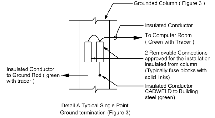
4.8 Computer installations shall utilize the ―single point‖ grounding scheme (see Figure 2). This scheme shall include a removable connection (Detail A, Figure 3) between the ground rod and the nearest grounded building steel column. This connection may have to be lifted temporarily to illustrate to the computer vendor that ―quiet‖ grounding exists. Figure 3 illustrates this scheme. A second removable connection shall be installed that allows complete isolation of the insulated computer wiring from ground; removal of this connection will allow testing for ―single point‖ ground (see Figure 5 and 6A). Note that removal of either connection may result in an unsafe grounding condition. A supervised controlled environment is required before connection removal and testing.
4.9 The computer ground network shall be insulated from building ground (except as noted in Section 4.8 and tied to the computer system service distribution transformer as shown in Figure 5. Note that a transformer system ground is not connected to the transformer case as generally found on all general-purpose applications (NEC 250-74, Exception 4). Typical service entrance connection diagrams (Figures 6, 7A, and 7B) are included to illustrate computer ground system isolation from distribution equipment case ground. Figure 6 shows computer ground bus connection to computer system distribution transformer, computer ground rod, and single-tie to building ground system. Figure 7A is a typical connection diagram of a distribution system servicing a computer installation having non-isolated equipment. Figure 7B is a typical connection diagram of distribution system servicing a computer installation having isolated equipment.
4.10 Control rooms may house conventional instrument panels as well as computer operator consoles. In most cases, the instrument panels and associated equipment are connected to building ground, while the computer operator‘s console and peripherals are connected to the computer ground system. Care shall be taken to ensure that these ground systems are insulated from each other, except for single point connection (Section 3.8). Figures 8 and 9 illustrate
installation and design considerations.
4.11 Various computer installations require conventional power service entrance features as well as special computer grounding. Figure 6 illustrates service entrance scheme interface to a computer ground bus.
4.12 Computer services result in prescriptive wiring methods when connecting to electrical distribution equipment for example, circuit breaker panels, disconnect switches and receptacles. Figures 10 and 11 are typical schematic diagrams of a computer instalIation. Note that Figure 10 is for non-isolated equipment while Figure 11 is for isolated equipment. Dropout contactor ―C‖ is typically not used for process control systems, for example DCS‘s or PLC‘s. The push button may be the ”maintained-off” type.
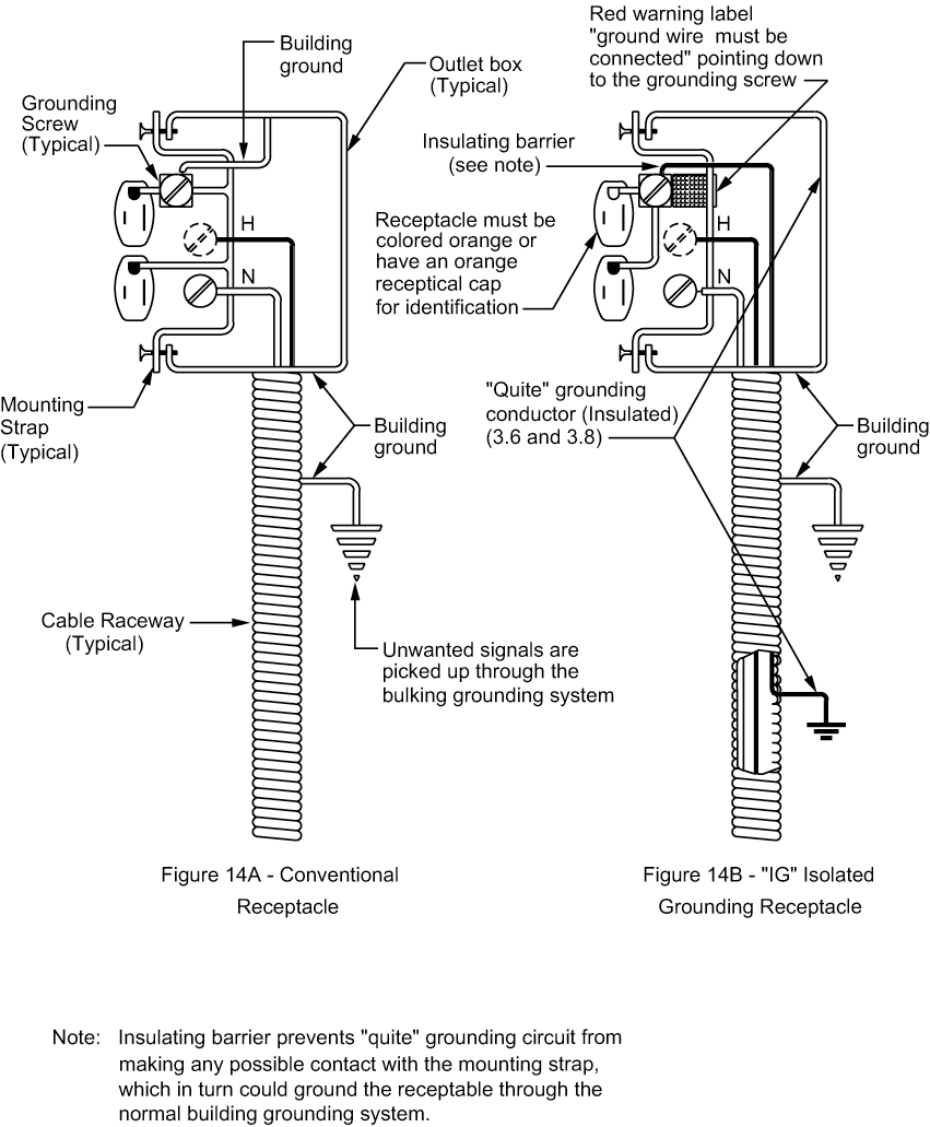
4.13 Computer installations require the use of isolated ground receptacles (Figure 14B); these receptacles differ from conventional receptacles (Figure 14A)
because the receptacle grounding screw is insulated from the receptacle housing. This allows installation of a ―quiet‖ ground to the receptacle grounding screw while the receptacle housing can be connected to the potentially ―noisy‖ building ground system. Extreme care is required in design and installation to ensure that both receptacle grounds (receptacle grounding screw and receptacles housing) are installed. Note that these receptacles shall be colored orange or provided with an orange receptacle cap to facilitate identification. Figure 12 provides a computer plug-receptacle selection guide.
4.14 Computers are frequently located in specially designed rooms, but peripheral equipment (video display terminals, operator consoles, I/O equipment) may be located in other areas. This may result in equipment from one system being installed in different ground planes. Within one building, there may be multiple ground planes due to different architectural construction features. This issue is addressed in Section 7.
4.15 Microcomputers are found in diverse types of equipment, for example sensors, transmitters, analyzers, and single loop controllers. Frequently, microcomputers embedded in equipment are ―transparent,‖ i.e., not readily recognizable. A careful review of the vendor‘s installation instructions is essential. A conservative approach to grounding would follow the recommendations in this section.
5 Distributed Control Systems (DCS)
5.1 DCS grounding practices described herein shall be verified with DCS vendor to ensure all requirements are met. Refer to Section 8 for interconnection information.
5.2 In addition to common grounding concerns, DCS systems typically require shield grounding for low-level signal wiring, logic system grounding, and sometimes
intrinsic safety barrier grounding.
6 Programmable Logic Controllers (PLC)
6.1 PLCs are suited to industrial environments. Items to consider in PLC grounding include the following.
6.1.1 Vendor shall provide grounding installation recommendation for customer review.
6.1.2 Vendor‘s PLC equipment ground shall be isolated (see Figure 1B).
6.1.3 PLC power supplies and I/O rack grounding requirements shall be reviewed for vendor‘s recommended grounding instructions and line noise installation criteria.
6.1.4 For power circuit distribution. (See Section 3.9)
6.2 Figures 10, 11, and 13 illustrate recommended grounding schemes for PLC equipment. To determine which scheme is appropriate for an application, follow the guidelines established in Section 4.
6.3 When programmable controller equipment is installed in existing buildings, the building‘s resistance to ground shall be checked to ensure that it does not exceed five ohms.
7 Peripherals
7.1 Peripherals include printers, video display terminals, tape loaders, disk drives and operators consoles. For the purpose of this standard, they will be broken into the
following three groups:
7.1.1 Peripherals located in computer rooms
7.1.2 Peripherals located in control rooms
7.1.3 Peripherals in other locations
7.2 Proper grounding of peripherals requires an analysis of vendor drawings, vendor recommendations, and interconnect isolation scheme.
7.3 Peripherals with isolated grounding (see Figure 1B) are recommended in all installations.
7.4 Figures 10, 11, and 13 illustrate recommended grounding schemes for peripheral equipment. To determine which scheme is appropriate, follow the rules established in Section 4.
7.5 When peripherals are located in control rooms having both a computer ―quiet‖ ground and a building ground, the location, mounting, and interconnect system ground isolation scheme determines to which ground system the peripheral shall be connected.
7.6 Peripherals‘ data communication schemes shall follow the recommendations in this section.
8 Interconnect system
8.1 All control equipment, for example PLC‘s and DCS‘s, have some type of communications system to collect data and transmit instructions. Use of interconnect equipment with isolated grounding (see Figure 1B) is recommended.
8.2 Experience indicates that interconnect system grounding is the area where most grounding mistakes are made. Part of this can be due to poor vendor documentation on the subject, lack of recognition for its need by the designer, or the difficulty in communicating this information to the installer by connection table listings.
8.3 The interconnect system may have its own computer equipment as its director. Analysis of its interconnection, isolation, and special grounding requirements is
mandatory.
8.4 When interconnect systems are located in a computer control room or computer console, grounding shall tie to the computer‘s ―quiet‖ ground as outlined in Figures 10, 11, or 13.
8.5 When interconnecting equipment is in different ground planes, the use of fiber optics with no metallic members is recommended.
Table I – Index To Grounding Application as Shown On Figures 1 – 14
Numbers in table refer to figure numbers : X = Not applicable
Figure 1 – Example Of “Non-Isolated” and “Isolated” Equipment
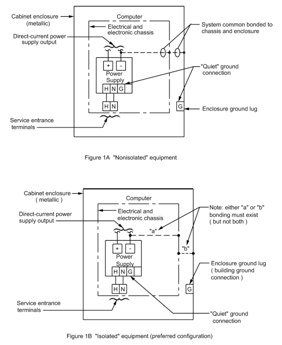
Figure 2 – Single-Point Ground
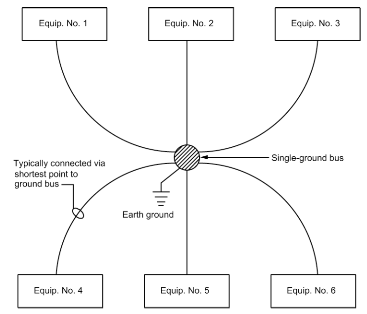
Figure 3 – Typical Building Grounding Plan – With Computer Room
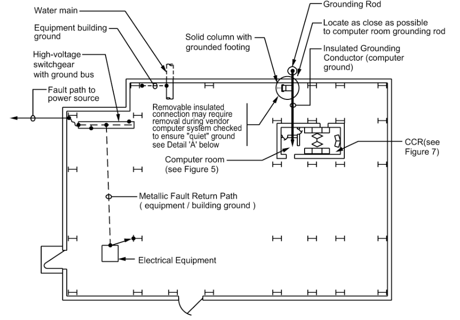
Figure 4A – Computer Equipment Grounding Scheme
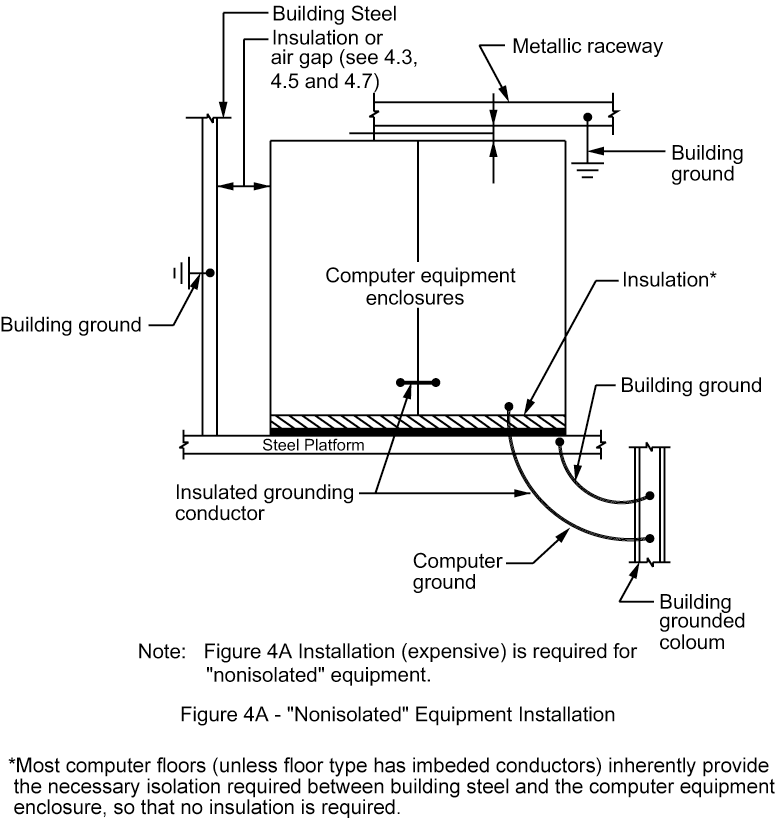
Figure 4B – Computer Equipment Grounding Scheme
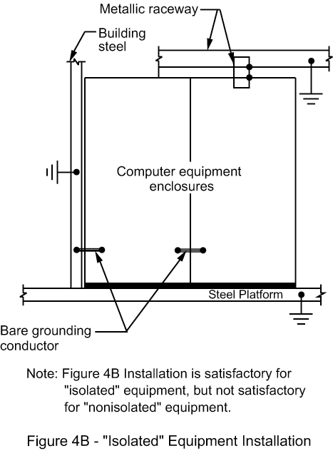
Figure 5 – Computer Room Power System Grounding Requirements
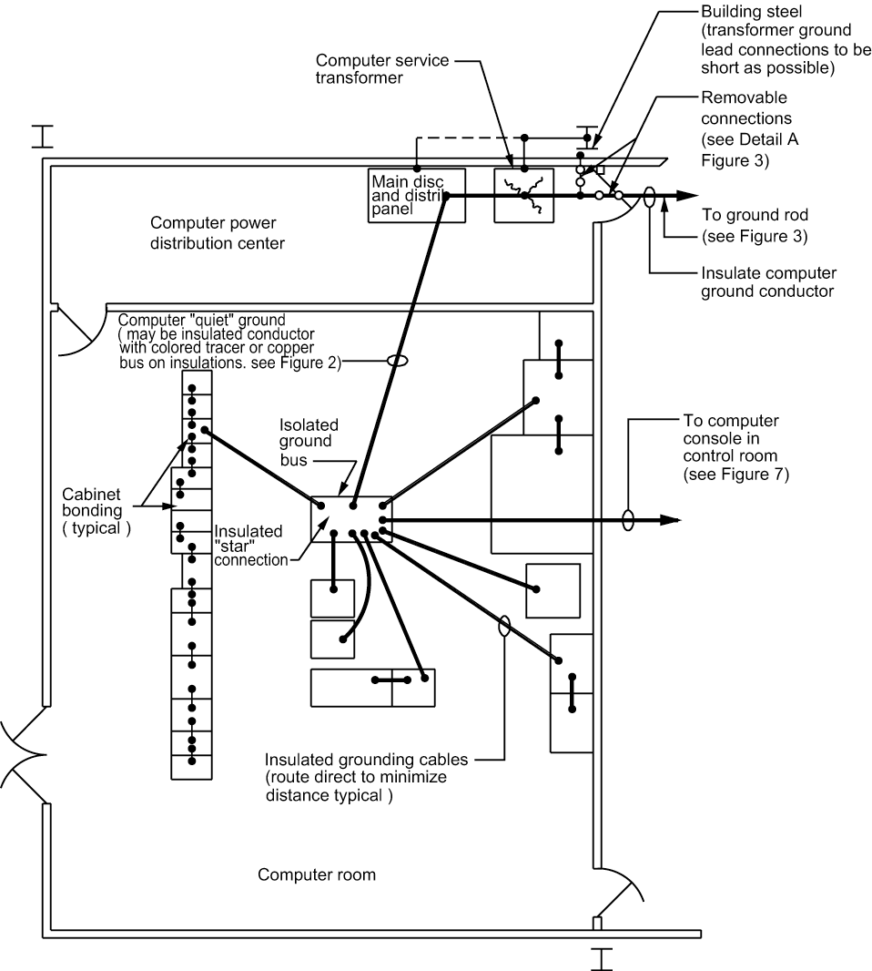
Figure 6 – Computer Power Service Grounding Requirements
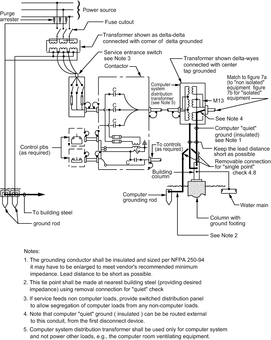
Figure 7A – Distribution System Connection Diagram for „Non Isolated‟ Equipment
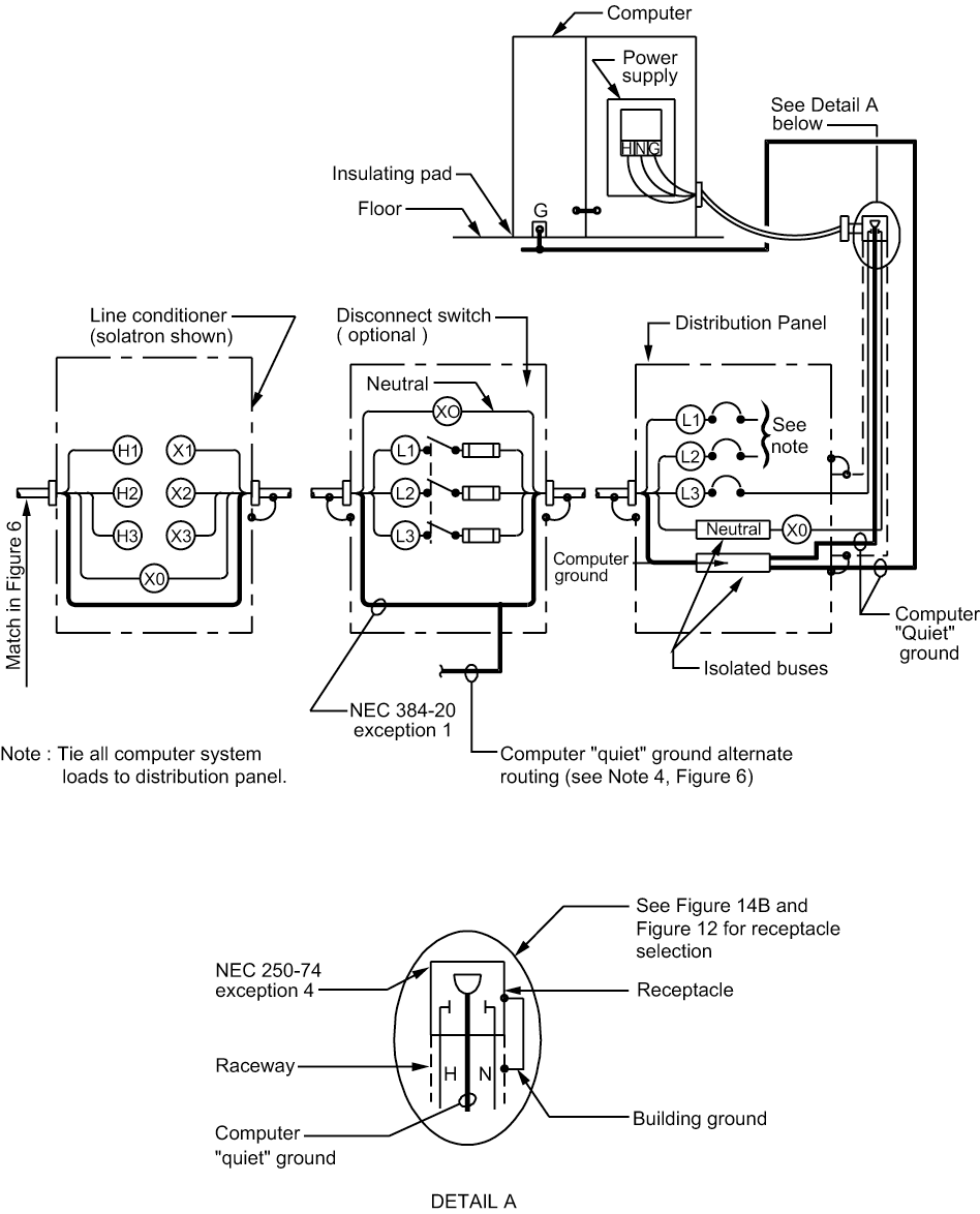
Figure 7B – Distribution System Connection Diagram for „Isolated‟ Equipment
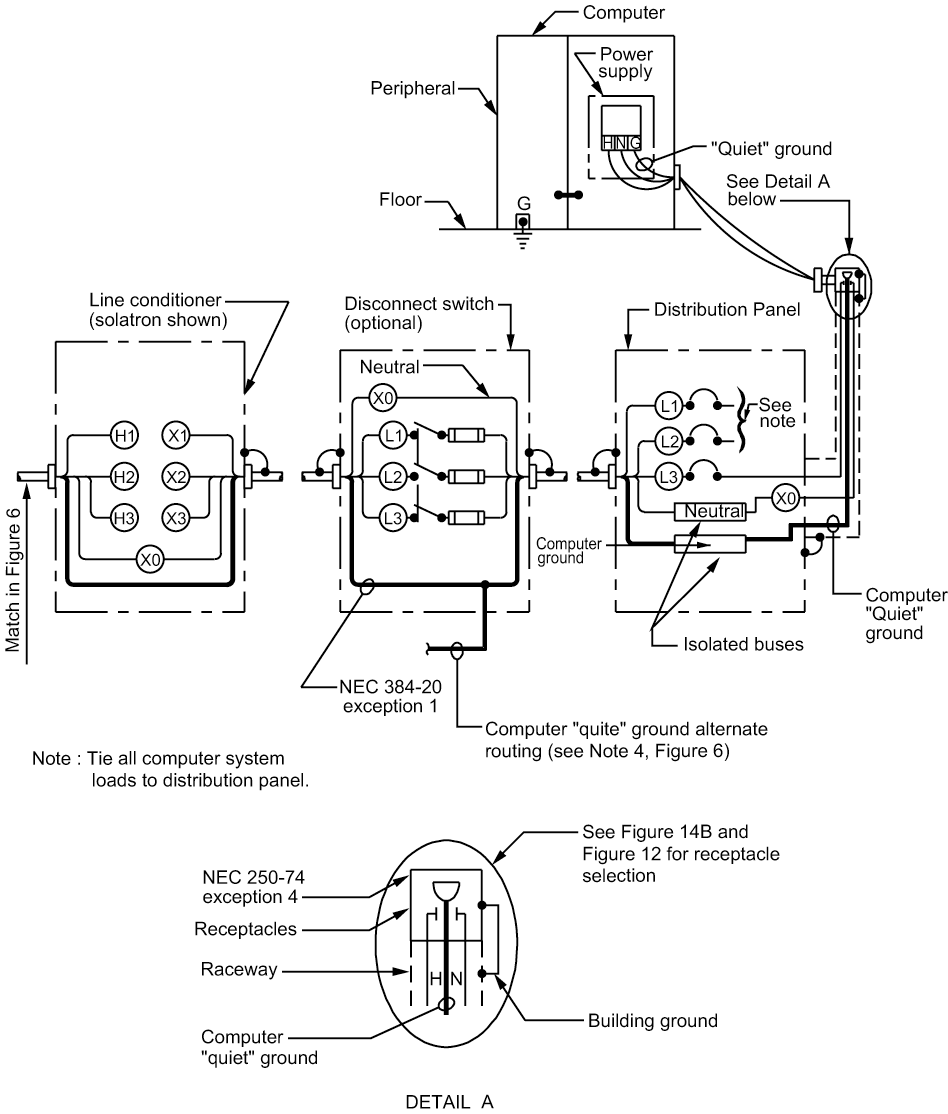
Figure 8 – Control Room Grounding (Shown with building and computer grounding system)
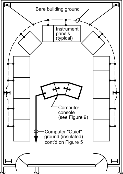
Figure 9 – Computer Console Grounding/Isolation
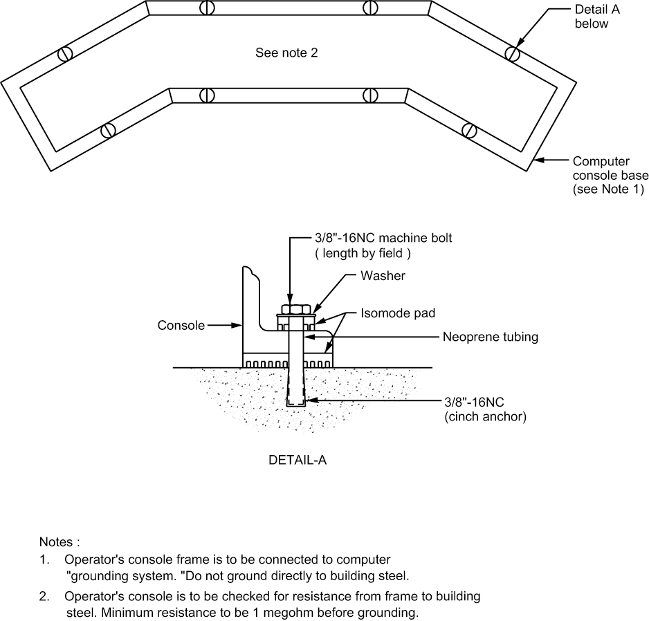
Figure 10 – Computer Power System – Grounding Requirements. Computer Service Schematic Diagram For “Non-Isolated” Equipment
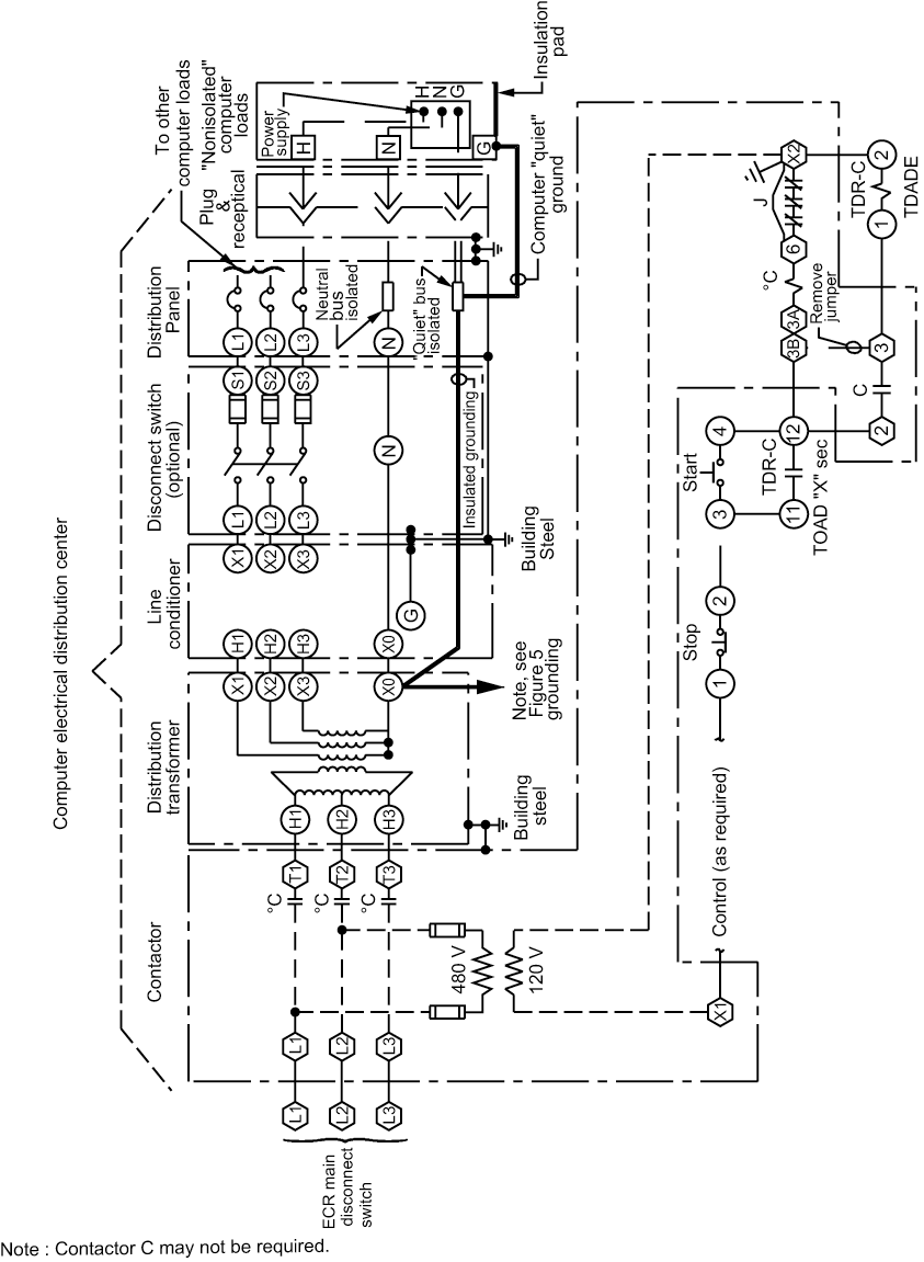
Figure 11 – Computer Power System – Grounding Requirements. Computer Service Schematic Diagram For “Isolated Equipment
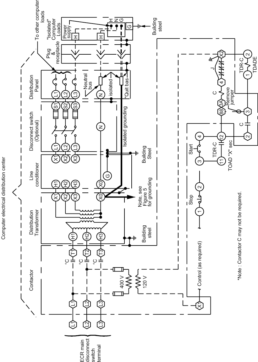
Figure 12 – Typical Plugs and Receptacles (See Notes 2, 4)
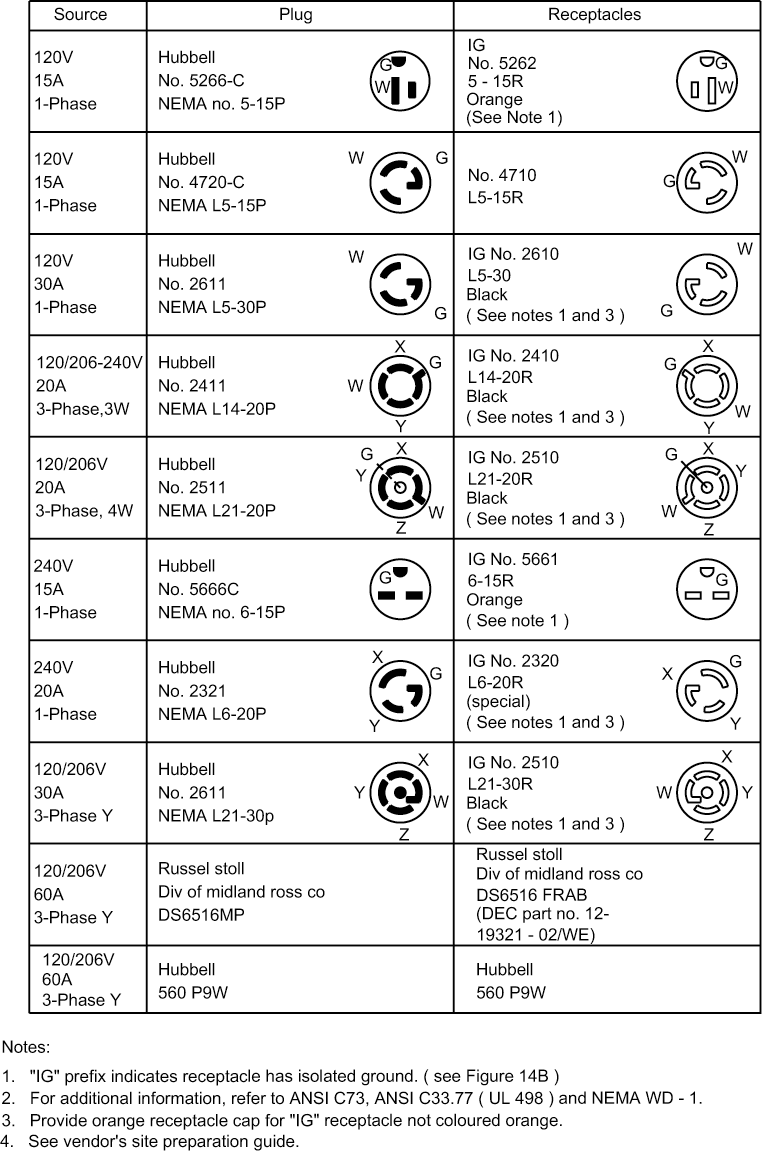
Figure 13-Computer Power System Grounding Requirement (see note 1)
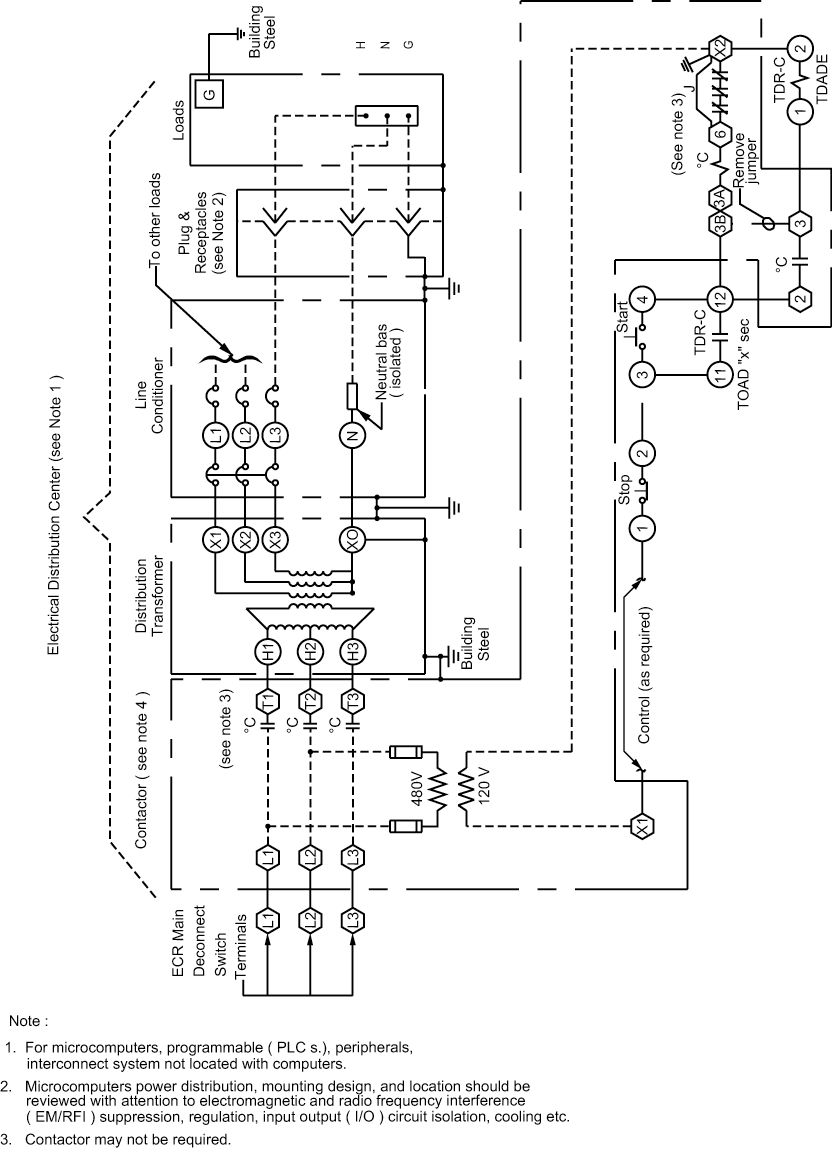
Figure 14 – Receptacle Configurations
