This article is about CONTROL VALVES EXPLANATION AND ITS TYPES and focusing to the engineers, technicians and supervisors. You will find lot of documents related to this article. Just navigate our website www.paktechpoint.com and find more articles. Please! Do not forget to subscribe our You tube channel also. Thanks in Advance.

 PLEASE SUBSCRIBE OUR PAKTECHPOINT YOUTUBE CHANNEL

VALVES EXPLANATION AND ITS TYPES
Liquids or gases flow from areas of higher pressure to areas of lower pressure. If a pipe is connected to a tank of water, the water flows out of the pipe opening because the pressure in the tank is greater than the pressure outside.
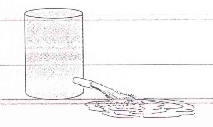
For a liquid or gas to flow, there must be a pressure difference, or drop.
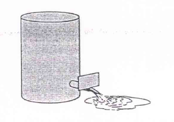
Suppose the opening of the pipe is partially closed with a piece of sheet metal, the amount of flow changes, and if the pipe is completely closed, the flow stops. Changing the amount of opening of the pipe changes the flow.In industrial piping, control of flow is of high importance. Mechanical devices that are used in such piping for flow control are called valves.
Basically, a valve stops flow through a pipe by closing the opening of the pipe. A valve that is partially open allows partial flow to exist, and is said to be in a throttling position.
Any valve can be in one of three positions: throttling, fully open, or fully closed.
GATE VALVES
If two pipes are joined closely together, flow can exist through them.
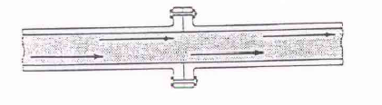
If a piece of sheet metal is inserted between the joints, flow stops.

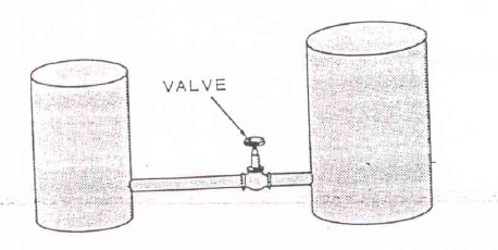
The drawing below shows two gate valves installed between two pipes.

A liquid is flowing through valve A. A gate valve stops flow by placing a metal gate across the opening. When the valve is completely open, the gate is raised out of the line of flow. In the open position, the gate causes practically no resistance to flow. When flow encounters resistance, or changes direction, turbulence and pressure drop occur.
When a gate valve stops the flow, the gate resists the pressure. Therefore the gate has to be strong enough to resist the pressure.

The pipes are always attached to the body of the valve.
The valve has a body with flanged ends with boltholes in them. The end of the pipe is also flanged and the pipe and valve are held together by bolts. To have a tight, leak proof connection, a gasket is inserted between pipe and valve.
The part of the valve that is mounted on top of the body to form a tight enclosure is called the bonnet. In the valve below, the bonnet and body are also bolted together.

Between the bonnet and body, a bonnet gasket is inserted for tight closure.

Stem Designs
The gate of this valve is attached to a stem, which goes through a stuffing box located in the bonnet.

The stuffing box is filled with a material called packing, the function of which is to stop leakage. If the stuffing box is not packed properly, the valve may leak. The stem of the valve below is threaded at the hand wheel end.
The threads of the stem are engaged by the threads of the bushing. The hand wheel and the stem are solidly connected so, as the hand wheel is turned, the stem bushing turns. Neither the gate nor the stem can turn.
As the hand wheel is turned, the thread bushing engages the thread of the stem, which makes the stem go up or down. As the stem rises, the gate also rises. If the hand wheel is turned in the opposite direction, the stem and gate are pushed downwards.In this type of valve the stem rises and, in doing so, rises outside of the valve.

This type of valve also has an outside yoke to support the hand wheel and bushing.

The abbreviation for this type of valve is OS & Y, which stands for outside stem and yoke. By looking at such a valve, an operator can tell if the valve is closed.
The valve stem may also be threaded on the bottom.

With such a stem, a gate is used that is threaded on the inside with the hand wheel solidly attached to the stem.

The part of the stem that passes through the bonnet has a flange on it, which prevents the stem from moving up or down. As the hand wheel is turned, the stem is turned and engages the threads on the inside of the gate. As the stem screws into the gate, it pulls up and if the hand wheel is turned in the opposite direction the stem unscrews and the gate is pushed down. In such a valve design, the stem does not rise and the abbreviation for this valve is NRS, which stands for non-rising stem.
This drawing shows a valve with bonnet threaded on the inside.

The threads of the bonnet engage the threads of the stem. The hand wheel and stem are also solidly connected so as the handwheel is turned, the stem turns. The threads of the stem engage the threads of the bonnet and, as they do so it must also move up or down. As the stem rises, the handwheel also rises. The stem is attached to the gate and, as the stem is raised, the gate rises.
Suppose that after a valve is installed, it leaks at point A.

Tightening the bolts may stop the leakage, but if not, replacing the gasket may be necessary. A worn gasket can cause leakage not only at point A but at point B as well. The leakage at point C is from the stem.

This type of leakage occurs due to improper packing of the stuffing box.
Both of these valves are open. Valve A is an NRS valve whilst valve B is an OS & Y valve. In areas where not much overhead clearance exists an NRS valve is used.

Gate Designs
The stem raises or lowers the gate, which is the part of the valve, which controls the opening.

When the gate is lowered to stop all flow, it makes a close fit with the seat rings. The seat rings and the gate make contact each time the valve is closed. As the gate is opened or closed, friction between gate and seats occurs. When friction occurs, wear also occurs.
When a valve is throttling, it regulates the rate of flow. Liquids or gases flowing under high pressure tend to erode metal that opposes their flow.

As the valve in B is throttling flow the water on the valve will be unevenly distributed. If the gate and seat rings are worn or eroded unevenly, positive shutoff upon closing is not possible.
The design of the gate can vary, the most common one being the solid wedge gate.
Such a gate is made out of one part. Complete shutoff with a solid gate is accomplished through a close fit between the gate and the seat rings.
A solid wedge gate is lowered into closed position.

The flow exerts pressure on one side of the gate. As the gate is raised, the flow will press against ring B. Whether the gate is raised or lowered, there is more friction between the gate and seat ring B which tends to wear out the one seat quicker. When seat ring B wears beyond a certain point, complete shutoff becomes impossible.
Another type of gate is the parallel disc and wedges gate.

This type of gate is made out of many parts. When closing, the parallel discs descend between two matching seats.

When the lower wedge, or spreader, reaches the stop, it cannot descend further. As the stem continues to descend, it forces the upper spreader onto the lower one and the discs are pushed outwards. This outward push pushes the discs against the seat rings. With this type of gate, a very tight closing is possible.
One side of this date is worn more than the other side.

Because of the tight closing produced by the wedging action, wear on one side still allows complete shutoff.
The discs are attached to the spreader in such a way that they can rotate when they are raised or lowered. Due to the rotation, when wear occurs it is more even. When opening such a gate, the first turn of the handwheel releases the spreader pressure.
In some systems, temperature changes and pipe expansion can warp the body of a valve, causing extreme pressure on the gate.

Warping can cause the gate to stick. Under such condition a parallel disc gate is used. As soon as the upper spreader is raised, it releases the wedging pressure. Under conditions where warping of the valve body can occur, a parallel disc gate is easier to operate.
Suppose a material with coarse particles is being handled. Because it has more parts, it is easier for a parallel disc gate to become fouled by particles. Therefore, a parallel disc gate should be used with relatively clean materials.
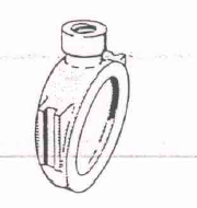
A solid gate can be used in a vertical position. Because of the wedges, it is easy for a parallel disc gate in the vertical position to malfunction.
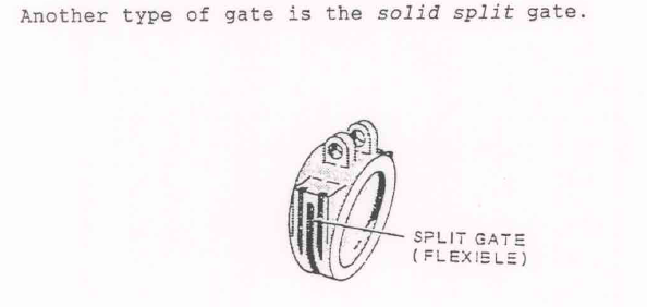
This gate is made out of one piece. The outer edges of such a gate are flexible. As the valve body wraps, it exerts pressure on the gate and the outer edges of the gate will give.
GLOBE VALVES
In a gate valve, the flow is in a straight line, without bends.

In the globe valve, the line of flow changes, and with the change of direction, turbulence occurs, which in turn increases the pressure drop across the valve.
The seats in a gate valve are perpendicular to the line of flow, whereas in the globe valve, the seat is parallel to the line of flow.

In the gate vale, all contact between the seating and the gate ends only when the valve is completely open.
Suppose a gate valve is being operated to increase flow, friction between the gate and seats end only when the valve is fully open. In a globe valve, the disc comes down onto the seat.

Flow starts as soon as contact is broken. In a globe valve, there is very little wear due to friction. When a gate valve is partially open, the entire gate is exposed to erosion, but when a globe valve is partially open, all of the disc is exposed to flow. Wear or erosion of a disc is likely to be even.
Because the gate in a gate valve is held between two seat rings, it cannot turn.Suppose the disc of a globe valve is free to rotate on the stem.

Liquid flowing through the opening between seat and disc can cause the disc to rotate. Due to the turning, point A on the disc will not always make contact with point A on the seat ring so the wear due to contact friction is more even on the disc of a globe valve. When the seat and disc wear evenly, after long use complete closure is still possible.
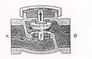
Suppose a globe valve is in a throttling position.
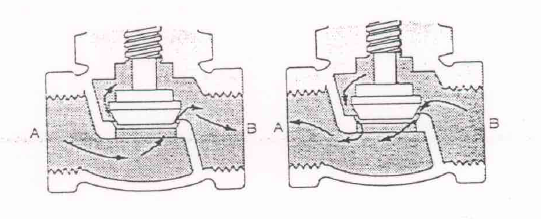
When the direction of flow is from A to B, the flow is from under the disc and there is no turbulence. If the flow is from B to A, the turbulence increases.
For the least pressure drop, a globe valve should be installed so that the flow is from under the disc. There are also globe valve, which can be installed as under.

The flow through an angle valve has fewer changes of direction than in a regular globe valve so the turbulence will be less.
The stem in a gate valve is only for raising and lowering the gate, but the stem in a globe valve, besides raising and lowering the disc, must also guide the disc into the seat ring.
In a gate valve, the gate is guided into place by the seating, whereas in a globe valve, the stem guides the disc.
Globe valve discs come in different designs with the most widely used one being the plug disc.
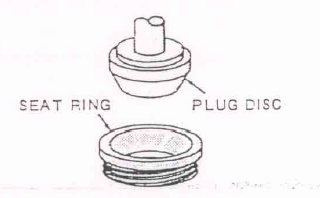
The plug disc is cone shaped. The seat ring has a matching shaped center. Abrasive particles in liquids can chip or nick the disc.
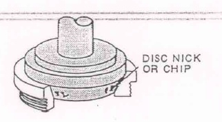
If the nicks or chips are not too large, tight closing is still possible. A plug disc is used for heavy throttling service because even after wear occurs, positive shutoff is still possible.
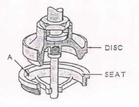
This drawing shows a composition disc. Here, the disc is made out of two different materials.

When completely closed, the seat ring makes contact with the soft part of the disc. Piping sometimes must handle liquids containing small, hard particles, which can accumulate on the seat or discs.

Such accumulation, if uneven, can prevent a plug disc from completely closing. When a composition disc is used, fine particles can embed themselves in the soft part of the disc but this does not prevent the disc from making a tight shut-off.
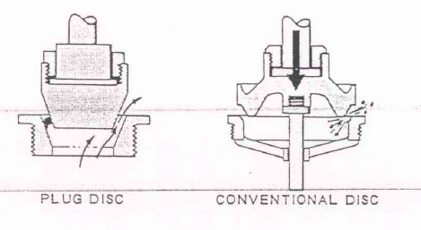
The drawing below shows a conventional disc. The disc-to-seat area is smaller than in a plug disc.
If such a disc is nicked or worn at point A, a tight closure is not possible. For extensive throttling service, a plug disc is preferred.
With a conventional disc, the contact between seat and disc is metal-to-metal.
In the valve below, a small piece of a hard substance is caught on the seat. A conventional disc can crush such a particle more easily than a plug disc.
Plug Valves
Another type of valve used in industrial piping is the plug valve.

The part of this valve that controls the opening is called the plug, which is located in the body of the valve and is made out of a solid piece.

The plug has an opening through it. During operation, the plug is not raised out of the body. The plug can be turned and when the opening of the plug is aligned with the opening of the valve, flow can exist. To stop the flow, the plug is turned a quarter turn.
The line of flow through a plug valve is straight, with the opening of the plug closely matched with the opening of the body of the valve. With the valve in the full open position, the plug offers little resistance to flow and there is little turbulence across the valve.
The pressure drop across a plug valve is less than with a globe valve and the valve can also be opened or closed quicker. A plug valve is made to stop flow by rotating the plug side across the opening. For complete shut-off with a plug valve, the plug and body must make a close fit, yet the plug has to be loose enough to be able to turn.
Each time the plug is turned, friction develops between the body and the plug and this can wear out both the plug and the body. If the plug is worn out, it will seat loosely in the body and so a complete shut-off will not be possible. The shank of the plug has a lubricant fitting that makes it possible to apply special lubricant to the plug itself. If adequate lubricant exists between plug and body, friction is reduced to a minimum, with the lubricant also serving as a sealant to prevent leakage. If lubricant is lost, excessive wear occurs due to friction, so a plug valve of this type should be lubricated regularly.
In terms of operating speed, the gate valve with a handwheel is relatively slow to open or close.
The drawing below shows a special kind of gate valve.

It does not have a threaded stem but the gate is attached to a stem, which is connected to a lever. If the lever is pushed a quarter of a turn to the right, the gate is raised to full open position.
Check Valves
This is a swing check valve.

The only moving part is a disc assembly that is attached to the body by a pivot pin. The pivot pin mounting leaves the disc assembly free to swing toward and away from the valve seat.
When there is no flow through the valve, the disc is positioned so that the valve is closed.
Liquid or gas only flows when there is a difference, or drop, in pressure between two points. If the pressure is higher at A than B, that will be the direction of flow.

Because the disc is free to move, the flow raises the disc to the open position. If the flow stops, the disc will swing back across the seat.
The line of flow through a swing check valve is relatively in a straight line so there is little turbulence. A check valve allows flow in only one direction and is therefore used to control the direction of flow.
The drawing below shows a lift check valve.
The line of flow through a lift check valve is similar to that through a globe valve. When flow occurs from A to B, it raises the disc, and as flow stops, gravity pulls the disc onto the seating. The lift check valve allows flow in only one direction, with the direction of flow always being from the underside of the disc.
Suppose that the same lift check valve is installed in a vertical position.

When flow occurs from A to B the disc is forced away from the seat ring. If flows stops, gravity will not pull the disc onto the seat ring. The lift check valve, therefore, will only work correctly if installed in a horizontal position. Based on its correct operating position, the lift check valve is called a horizontal lift check valve.
The lift check valve also comes in another design.

When flow occurs from A to B, the disc raises, and when flow stops, gravity lowers the disc onto the seat. If mounted in a vertical position, this lift check valve operates properly. This is a vertical lift check valve.
The ball valve is also a check valve.

The line of flow through such a valve is not in a straight line. The part of the valve that controls the opening is a ball. When flow occurs, the ball is raised by the force of the flow. As flow stops, gravity pulls the ball into the closed position. The ball chech valve also comes in two designs.
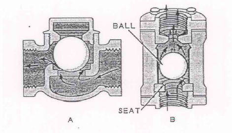
Valve A is a horizontal ball check valve and valve B is a vertical ball check valve.
Butterfly Valves
The drawing below shows two totally different types of butterfly valve, the so-called “rubber lined” valve and the “high performance butterfly valve.

‘Rubber lined” is the generic name for any butterfly valve that has a disc totally concentric with the stem. Almost all of these valves also have a single-piece resilient seat or liner that wraps over the end-flange sealing surface. These valves are almost always limited to a specific maximum pressure, which is less than the flange rating, due to the liner and disc design. Their service is also limited by temperature.
In the other type- the “high performance” valve – the center of the disc is offset slightly outward from the centerline of the shaft, with a spherical sealing surface on the disc, and the shaft offset slightly from the centerline of the valve body. This valve seals by a combination of shaft torque and line pressure, and is normally rated to full ANSI flange rating, but may still have a maximum temperature limitation due to the seat material.
These valves can be built in either a “wafer” or “lug” design. The wafer design has bolts extending from one line flange past the valve into the other line flange. The lug design has tapped holes through which bolts are threaded from each flange.
Pinch Valves
The body of these infrequently installed valves consists of a length of flexible material similar to hose. The operating mechanism is a set of brackets that clamp down on the outside of shut off, and will even close when entrained solids are present in the flowing fluid. In this valve the compatibility of the hose material with the process stream is critical.
Operators
Suppose that a non-rising stem gate valve is required in a given piping installation. The NRS gate valve is more likely to ensure tight closure, but if both high speed and tight closure are needed, one way to make the gate of the NRS valve slide shut faster is to make the s tem rotate faster.
The drawing below shows a motor attached to the stem of the valve.

A motor-driven OS & Y valve probably shuts faster than one operated by hand. If the valve is too big to be operated by one man, a motor can provide the extra power needed to turn the stem.
Mechanical operators such as motors can make valves open and shut faster than a man can, and can operate the valve with greater power than several men at once.
If a valve is located where a man cannot reach it easily and a motor is connected to it, the valve can be operated remotely. Remote operators also make it possible for one man to operate several valves at once.
Mechanical operators must be selected to meet special requirements. For example, in any location where there could be explosive fumes, a spark-causing device is undesirable. Fire can melt electric wires or short out electric motors, so in conditions where fire or explosion can occur, an electric operator is generally unsafe.
Some motors use other sources of power.
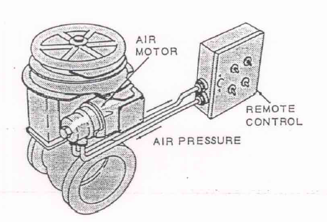
Above is a motor that operates on air pressure. Air operators can be supplied with the compressed air that drives them either by hose or hard pipe. This operator cannot be short-circuited by fire and is desirable where danger of explosion exists. It can also be controlled from a remote location.
There are times when an overhead valve is inaccessible and an electric or air operator cannot be installed on it.
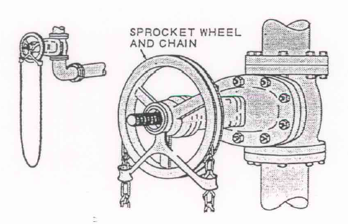
The drawing shows a sprocket wheel and chain arrangement that can be attached. As the chain is pulled, the sprocket wheel turns, and as the wheel is attached to the stem, the stem moves. Although the sprocket wheel does increase the power somewhat, the chain operator is primarily used to increase accessibility.
A valve located within easy reach but requiring much strength can still be operated without a motor.
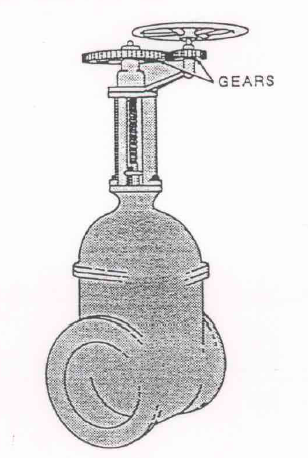
This valve is operated through a system of gears and is called a gear operator.
Operating Difficulties
Accumulation of sludge or particles can foul a valve.

If too much is accumulated at point A, the valve will not be able to close completely. If the accumulation is in the bonnet area, the valve will not be able to open completely.

If this happens, the gate does not rise as the stem is raised. If conditions permit, the valve should be dismantled and repaired or replaced. At times, conditions do not permit the dismantling of a valve even though the gate must be raised.
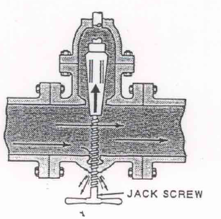
Drilling the bottom of the valve and screwing in a jackscrew will raise the gate but can be dangerous due to possible leakage.

Fist, a coupling is welded to the body of the damaged valve, and to this coupling a nipple, gate valve, and a nipple with a stuffing box is attached. After the attachment is set up, the drill is inserted through it.
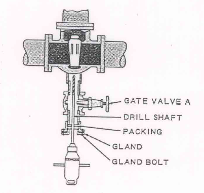
As the bolts attaching the gland to the nipple are tightened, the packing is compressed around the driller shaft and prevents leakage when the body of the damaged valve is pierced.
After the hole is drilled, the drill is pulled out past the gate valve A.
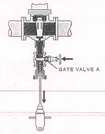
Valve A is closed, thus stopping any leakage that may exist. After entirely removing the drill, a tap is inserted and once again the gland is tightened. Now the temporary gate valve A is opened permitting the tap to be inserted further. After the drilled hole is tapped, the tap is removed and the jackscrew is inserted in the same manner.
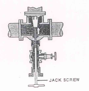
As the jack screw is screwed in, the gate rises and, due to the attachment, leakage is prevented.
Suppose that the stem bushing of an outside yoke valve is stripped or broken.
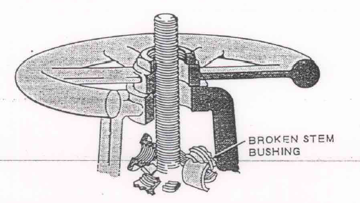
The hand wheel will not raise the stem. If possible, the stem bushing should be replaced but, in case of emergency, the gate can still be raised.

An overhead hoist is installed and connected to the stem and, as the hoist is operated, it raises the stem. Tapping the stem with a softheaded hammer will close the gate.
Every valve with a stem has a stuffing box.
The stuffing box is filled with packing.
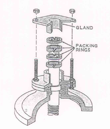
Once cut to the proper length, the packing is installed in rings so that each cut is opposite the other.
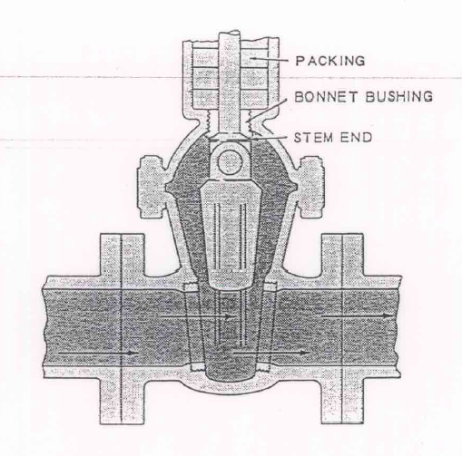
If the valve is opened as far as possible, the stem end and the bonnet bushing make a tight fit. This is called back seating, and in actuality, the stem end and bushing form a valve within the bonnet.Back seating can be dangerous and should only be done in cases of severe emergency.
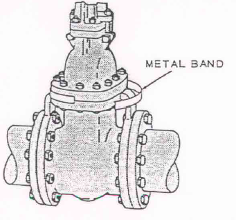
Valves may develop leaks in various places while in service.

When a leak develops at point C, it is probably due to improper packing.
good explantion of control valve