The Coriolis Mass Flowmeter is a sophisticated instrument designed based on the Coriolis force principle, widely employed for process detection and custody transfer in various industries. Its versatility extends across petroleum, petrochemical, chemical, pharmaceutical, paper-making, food, energy, and other sectors. This advanced flow and density measurement device finds applications in measuring liquids, gases, and slurries with precision. Below are key aspects of the Coriolis Mass Flowmeter.
![Coriolis Mass Flowmeter Working Principle, Diagram, Calibration, Advantages [PDF]](https://paktechpoint.com/wp-content/uploads/2024/01/image-39-1000x1024.png)
Gaspard Gustave de Coriolis (1792–1843), a French mathematician and mechanical engineer, is renowned for his groundbreaking work on the Coriolis effect, a phenomenon observed in rotating systems. His papers focused on energy transfer in rotating systems, particularly in the context of waterwheels. The Coriolis effect, named after him, has become a fundamental concept in meteorology and oceanography. Coriolis’ legacy lies in his significant contributions to our understanding of rotating system dynamics and the impact of the Coriolis effect on natural phenomena.

Coriolis Mass Flowmeter Working Principle
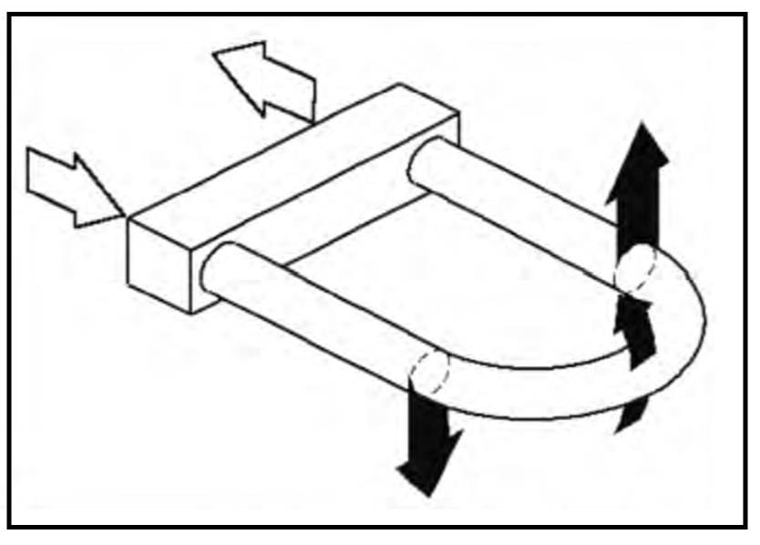
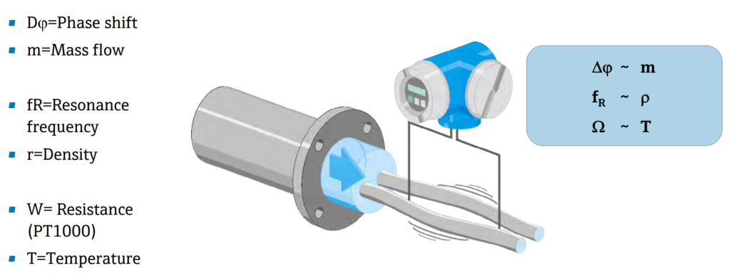
The Coriolis Mass Flowmeter operates based on the Coriolis force principle. Electromagnetic coils on two parallel measuring tubes induce vibrations at a fixed frequency. When mass flows through, Coriolis force causes tube deflection sensed as a phase shift. The phase shift, proportional to mass flow, is detected by electronic pick-ups. The flow rate is calculated from this phase shift. The vibration frequency, determined by the total mass and inner flow, changes with mass flow density, allowing density calculation. The temperature sensor on the tubes, working with the measuring circuit, provides real-time temperature.
Measurement Signal

Frequency-shift by Mass-shift
The resonance frequency of a swinging system is indeed influenced by both the stiffness (c) and the mass (m). When the mass increases while keeping the stiffness constant, the resonance frequency tends to decrease. This relationship highlights the dynamic interplay between mass and stiffness in determining the natural frequency of a system. If you have more questions or if there’s anything specific you’d like to delve into, feel free to ask!
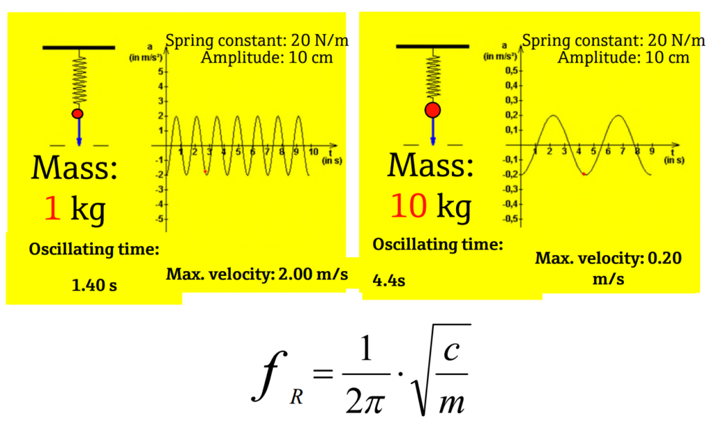
The higher the mass the slower the frequency!
The smaller the mass the higher the frequency!
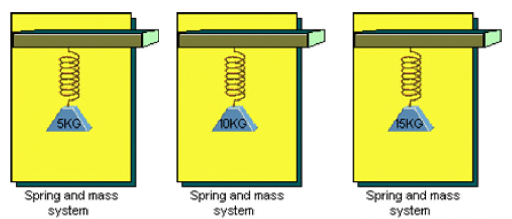
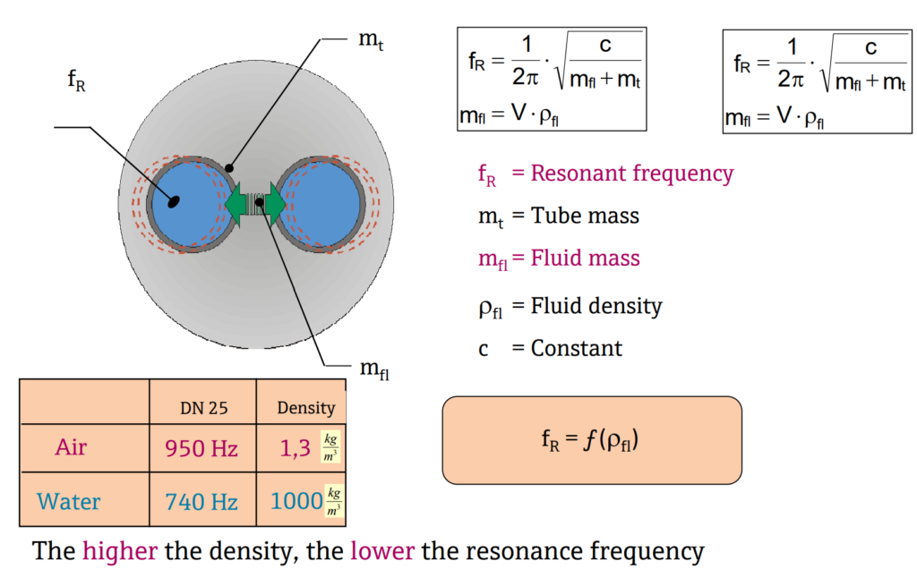
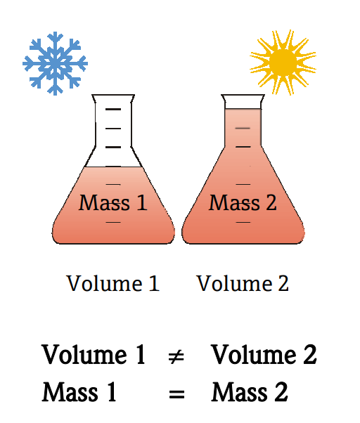
The higher the density the bigger the mass:
Overview of direct measuring variables
Installation of Coriolis Mass Flowmeter
Installation Process
- Location: Determine the sensor installation location, considering the installation area, pipeline, transmitter location, and valves.
- Direction: Decide the sensor installation direction within the pipeline.
- Installation: Install the sensor and transmitter in the pipeline.
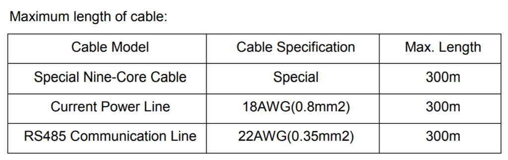
- Connection: If the Coriolis Mass Flowmeter is installed separately, connect the sensor and transmitter using a special Nine-Core Cable.
- Start-up.
Position Selection
- Avoid Interference: Place the sensor away from interference sources like pumps to prevent pipe mechanical vibration. If using sensors in series along the same line, ensure a distance of at least 2 meters to avoid vibration resonance.
- Temperature Changes: Be cautious of temperature-induced expansion and contraction of the process pipeline. Avoid installing the sensor near an expansion joint to prevent transverse stress affecting zero and measurement accuracy.
- Electromagnetic Interference: Keep the sensor at least 5 meters away from industrial electromagnetic interference sources such as large power motors and transformers.
- Fluid Fill and Pressure: Position the sensor where its measuring tube is always filled with fluids, maintaining a certain pressure at the outlet. Install it in a lower position in the pipeline.
- Basic Requirement: Install the Coriolis Mass Flowmeter lower in the pipeline to ensure fluid filling during zero-point calibration. Transmitter installation should be in an environment with a temperature of -40~+55 ℃ and humidity <90%.
- Dangerous Area: Confirm that the explosion-proof class on the Coriolis Mass Flowmeter’s nameplate matches the application environment regulation before installation.
- Straight Pipe: The Coriolis Mass Flowmeter does not require a special straight pipe upstream or downstream. If multiple mass flow transmitters are installed in the same pipe, ensure a length of more than 2 meters between any two sets.
Valve
- Zero-point calibration must be conducted after installation.
- Close the downstream stop valve before zero-point calibration, followed by closing the upstream stop valve.
Coriolis Mass Flowmeter Direction
Basic Requirement:
- The Coriolis Mass Flowmeter should be installed to ensure the measuring tube is filled with the measured medium.
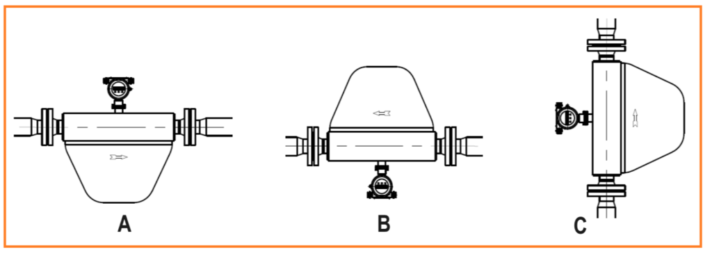
- For horizontal installation:
- Measuring tube under the pipe for liquid or slurry (see Drawing A).
- Measuring tube on top of the pipe for gas (see Drawing B).
- For vertical installation:
- Measuring tube installed beside the pipe for liquid, slurry, or gas (see Drawing C).
Flow Direction:
- A flow direction arrow indicating the proper flow direction is on the front of the sensor; install the Coriolis Mass Flowmeter accordingly.
- For vertical installation:
- If the process medium is liquid or slurry, the flow direction should be from down-to-up.
- If the process medium is gas, the flow direction can be either down-to-up or up-to-down.
- The transmitter can be mounted with a 90° rotation as needed during installation.
Sensor Installation
Basic Requirements:
- The installation of the Coriolis Mass Flowmeter should be in a straight line.
- Do not support the pipeline with the FMC Coriolis Meter (refer to diagram).

Installation of the FMC Coriolis Meter 6” or Larger:
- It is advisable to support the sensor of the Coriolis Mass Flowmeter using rubber connectors as a buffer.
Coriolis Sensor General Remarks:
When considering Coriolis sensors, several general remarks apply:
- Dual-Tube Design / Single-Tube Design:
- Dual-tube instruments are inherently balanced against external disturbances as the movements of the tubes compensate for each other.
- Endress+Hauser places special emphasis on the design of single-tube instruments. In competitor’s single-tube instruments, vibration immunity can be a weak point.
- Material Choice:
- Stainless Steel: Stainless steel has a relatively large thermal expansion coefficient, making it responsive to temperature changes with high expansion. If a steel meter is specified above 100 ºC, it must feature bent tubes to prevent material damage from thermal expansion stress. The same applies to most alloy materials like Hastelloy C.
- Titanium: Titanium, with its lower thermal expansion coefficient, is used for all straight tube meters specified above 100 ºC.
Coriolis Mass Flowmeter Sensor Diagram:
The Coriolis Mass Flowmeter sensor features a rigid carrier tube that is designed to withstand all loads within a piping system. This design characteristic promotes a “Fit and Forget” approach, meaning that once installed, the sensor requires minimal maintenance or additional measures. Unlike some other flow measurement technologies, Coriolis sensors do not necessitate extra measures such as additional pipeline support, and they can accommodate variations in pipe mismatch without imposing restrictions. The robustness of the rigid carrier tube enhances the reliability and longevity of the Coriolis Mass Flowmeter, contributing to its reputation as a reliable and low-maintenance flow measurement solution.

3.6 Start-up
Zero-point Calibration:
- Zero-point calibration establishes the base point for the flow meter.
- After initial installation or reinstallation, perform zero-point calibration for the Coriolis Mass Flowmeter.
- Before calibration, close the valve downstream of the flow sensor to ensure no fluid is flowing through the pipe.
- The sensor should be filled with process fluid, and the temperature change during calibration should not exceed ±10℃.
- Avoid zeroing the flow meter when fluids are in motion, as it may result in significantly smaller measurements. In such cases, either stop using the meter or re-zero it before further use.
Instrument Coefficient:
- Each Coriolis Mass Flowmeter comes with predefined instrument coefficients, indicated on the calibration report and nameplate.
- Users typically do not need to set instrument coefficients unless either the sensor or transmitter is replaced.
- Coefficients from the calibration report are also printed on the nameplate.
- Normally, the sensor and transmitter are coupled, and the coefficient is input into the transmitter. The meter can be used without additional changes.
Features of Coriolis Mass Flowmeter:
In comparison to traditional flow measurement methods, Coriolis Mass Flowmeters offer several distinct advantages:
- Direct Mass Flow Rate Measurement:
The Coriolis Mass Flowmeter can directly measure the mass flow rate in the measuring tubes without requiring intermediate conversions. This direct measurement minimizes errors, ensuring high accuracy, excellent repeatability, and a wide turndown ratio.
- Wide Range of Flows:
These meters can handle a diverse range of flows, including steady uniform flows of fluids with common viscosity, high viscosity fluids, non-Newtonian fluids, slurries containing solid components, and liquids with aeration. This versatility makes them suitable for various fluid types and applications.
- Low Vibration and No-Moving Parts:
The measuring tube experiences minimal vibration, and it can be considered as having no moving parts. This characteristic reduces the need for meter maintenance, contributing to enhanced stability and an extended operational life.
- Comprehensive Measurement Capabilities:
In addition to mass flow measurement, Coriolis Mass Flowmeters can measure and output data for density, temperature, and even consistency. This multifunctional capability provides a comprehensive set of information for precise process monitoring and control.
These features position Coriolis Mass Flowmeters as advanced instruments with a high level of accuracy, broad applicability, and minimal maintenance requirements. The ability to directly measure mass flow, accommodate various flow conditions, and provide additional measurements like density and temperature underscores their efficiency and reliability in diverse industrial applications.
Traditional Mass Flow Measurement
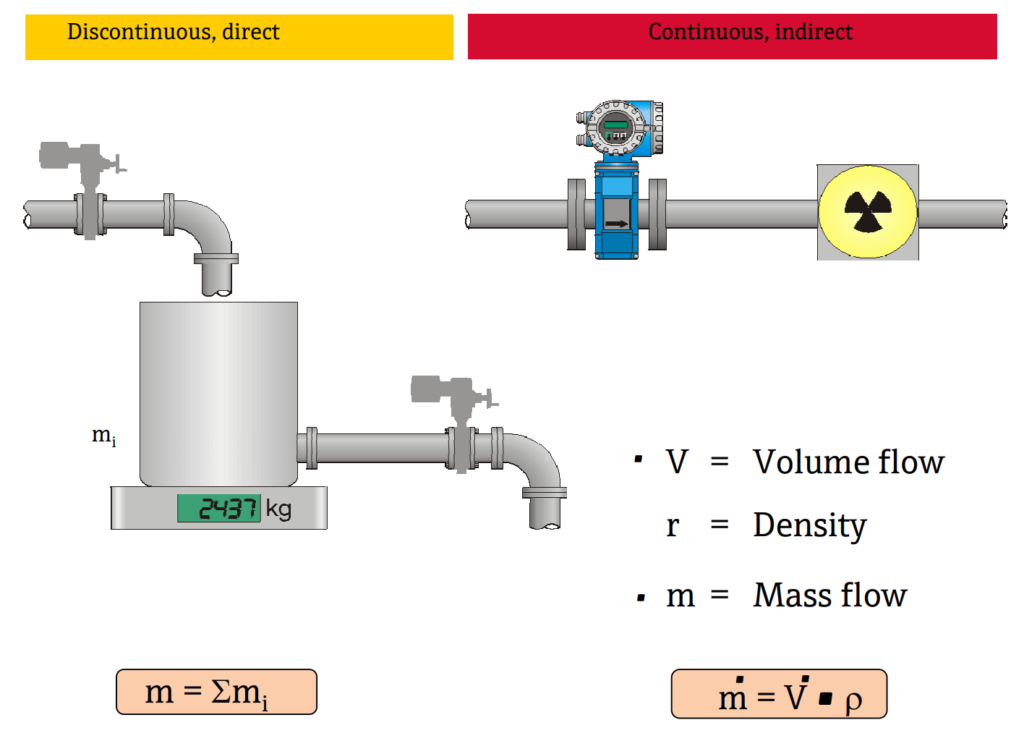
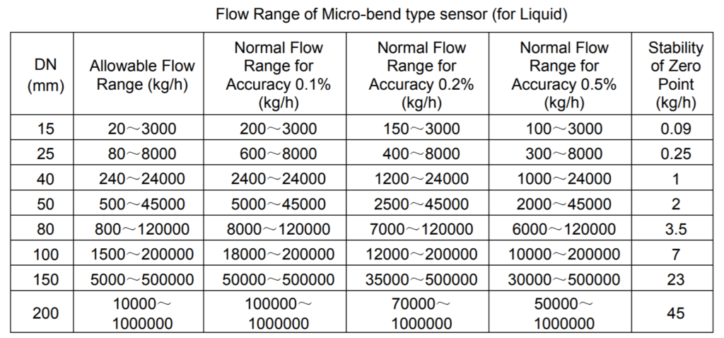
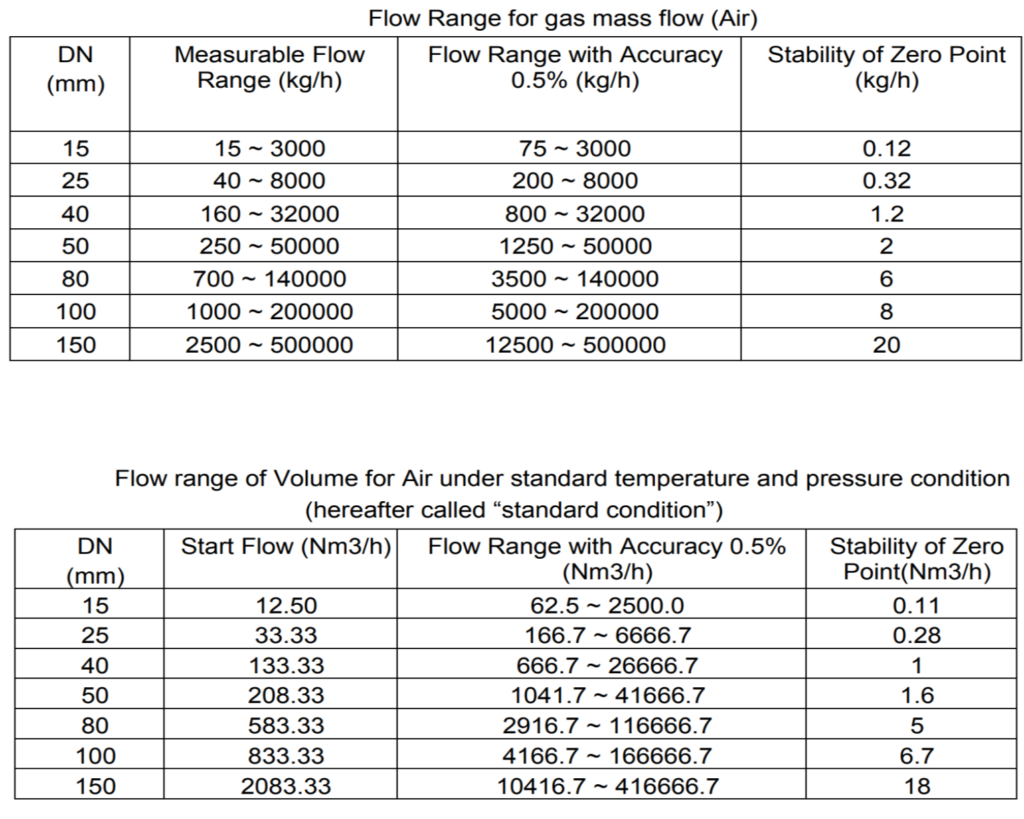
Technical Specifications
Here we are taking example of FMC 5000 Coriolis Meters and all data from manufacture data sheet.

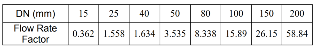
Flow rate factor for calculating medium speed
The formula provided for calculating the inside medium flow rate for Air measurement using an FMC Coriolis Meter is as follows:
Inside Medium Flow Rate = Volume Flowrate under working condition/Flow Rate Factor
Flow Rate Factor is used to adjust the flow rate of the Coriolis flow meter when connection size reducing is common for Air measurement applications. The formula allows for the accurate determination of the actual flow rate of the medium in consideration of the specific working conditions and the characteristics of the flow rate factor.
Advantages of Coriolis Mass Flowmeter:
- Capable of measuring both conductive and non-conductive liquids.
- Provides the advantage of standardizing on a single flow technology.
- Ensures mass measurement is independent of temperature variations.
- Eliminates temperature influence, contributing to enhanced process control and stability.
- Offers high accuracy and repeatability in flow measurement.
- Contributes to improved process control by minimizing fluctuations in the measured value.
- Maintains accurate measurement even in the presence of viscosity and density changes.
- Ensures high process stability even when fluid properties change.
- Operates effectively across a wide range of flow rates.
- Enhances process control, particularly in low-flow conditions.
- Absence of moving parts reduces wear and tear, contributing to increased operating time.
- Lower maintenance costs due to reduced wear and tear and improved operating efficiency.
FAQs about Coriolis Mass Flowmeter
What is the principle of the Coriolis effect?
Are Coriolis meters bidirectional?
Discover more from PAKTECHPOINT
Subscribe to get the latest posts sent to your email.