This article is about DC UPS system design in commercial buildings, plants and refineries. In this article explained with pictures about Types, , Industry Design, Components, Single line Diagram SLD, Modes of operation, Charging mode, Maintenance, Alarm List & History List, Battery Charger Shutdown, Battery bank Shutdown, Battery Charger start up, Battery Bank startup, Inspection and visual check of DC UPS System.
DC UPS SYSTEM INDUSTRY DESIGN | PRINCIPLE | BASICS
Purpose of DC UPS System
Provide uninterrupted power to Switchgears, Relays, Automation system & Emergency lighting
Type of DC UPS System
- Standalone
- Parallel redundant
- With single battery bank
- With dual battery bank
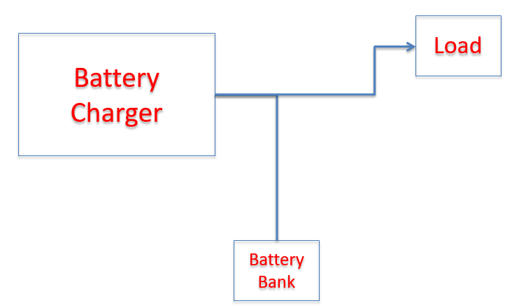
Standalone DC UPS System
Standalone DC UPS System
Advantage
- Reduced cost of installation.
Disadvantage
- Less reliability.
- Difficult in maintenance.
- Chances of loss of power to critical equipment.
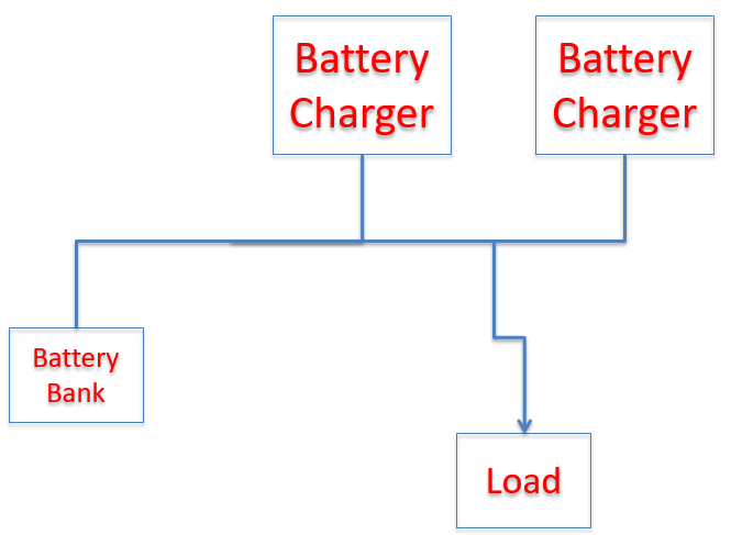
Parallel Redundant DC UPS System with single battery bank
Parallel Redundant DC UPS System with single battery bank
Advantage
1. Reduced cost of installation (Battery).
Disadvantage
1. Less reliability. 2. Chances of loss of power to critical equipment.
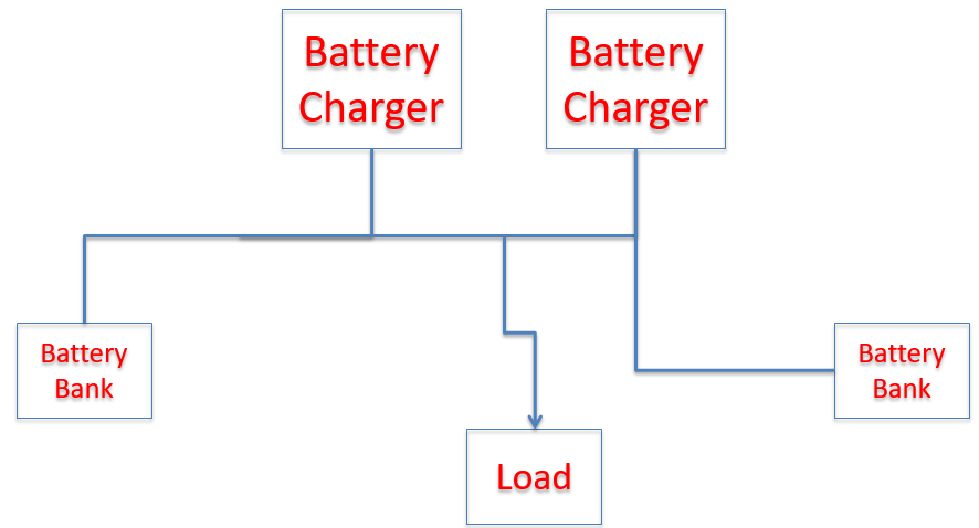
Parallel Redundant DC UPS System with dual battery bank
Parallel Redundant DC UPS System with dual battery bank
Advantage
- Highest reliability.
- Easy to maintain.
Disadvantage
- Higher cost of installation.
Components of DC UPS System
- Rectifier / Battery Charger
- Battery Bank
- Load Distribution
What is UPS Rectifier
A component of DC UPS, converts AC voltage in to DC voltage.
It is designed for feeding continuous load and charging the battery.
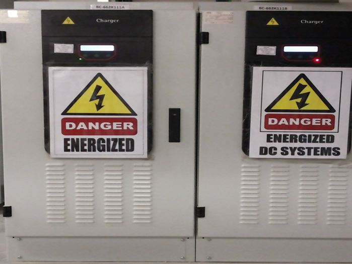
AEG Charger has Input voltage rating of 480V, 60 Hz
AEG Charger has output voltage rating of 125 Volt
We have 20 Amp, 50 Amp, 75 Amp, 100 Amp, 150 Amp Chargers
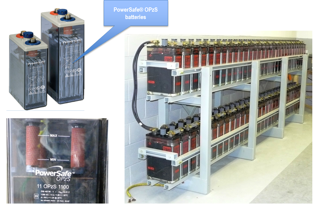
UPS Battery Bank
A component of DC UPS, stores energy for feeding the critical load in case of Mains failure/ Charger failure .
It is designed for feeding load as per designed duty cycle.
we have 200, 250, 300, 350, 420, 490, 600, 700, 800, 900 Ah
11, 12, 15, 25 Ah
Designed backup time is 8 Hrs.
Load Distribution boards
These are used for terminating connected critical loads.
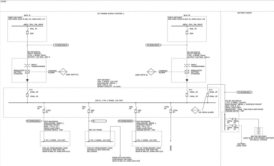
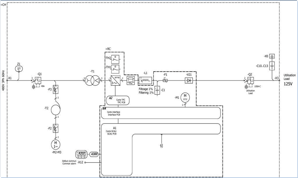
DC UPS SINGLE LINE DIAGRAM
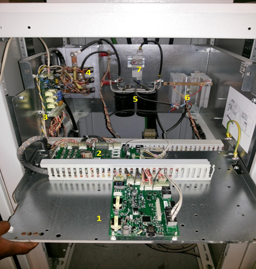
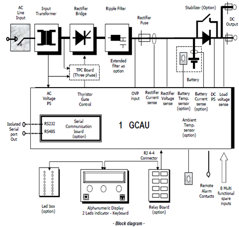
1. A1-GCAU PCB
2. A4- Interface PCB
3. A2- TPC PCB
4. Thyristor bridge
5. Filter Capacitor
6. Reverse blocking diode
7. F1 Fuse
The mains voltage is applied to the primary winding of the power transformer via the standard mains input switch or other optional circuit-opening devices. The rectifier is then in service, provided no fault has been detected and/or stored by the monitoring systems. The power converter rectifies the transformer secondary voltage. The single-phase power converter consists of a mixed diode/thyristor bridge; the three-phase power converter consists of a thyristor bridge. The rectifier current is smoothed by an inductor and the voltage is filtered by capacitors. The rectifier current is sensed across a rectifier shunt.
The GCAU control card is supplied either by an auxiliary secondary winding of the transformer or the battery. This card controls the power converter from internal references (which depend on the battery type and the current charge mode) to regulate the rectifier output voltage and/or current. There is a protective fuse inserted in the positive branch of the rectifier.
The battery current is sensed across a battery shunt (option). A temperature sensor senses the battery ambient temperature and compensates the rectifier voltage according to the temperature (option).
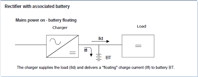
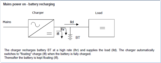
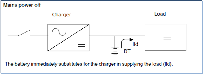
DC UPS Modes of operation
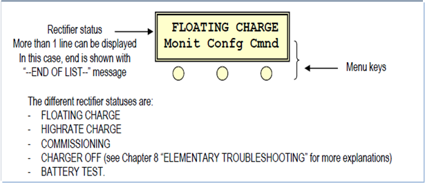
DC UPS Operation
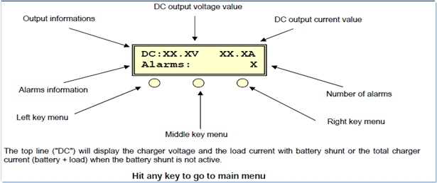
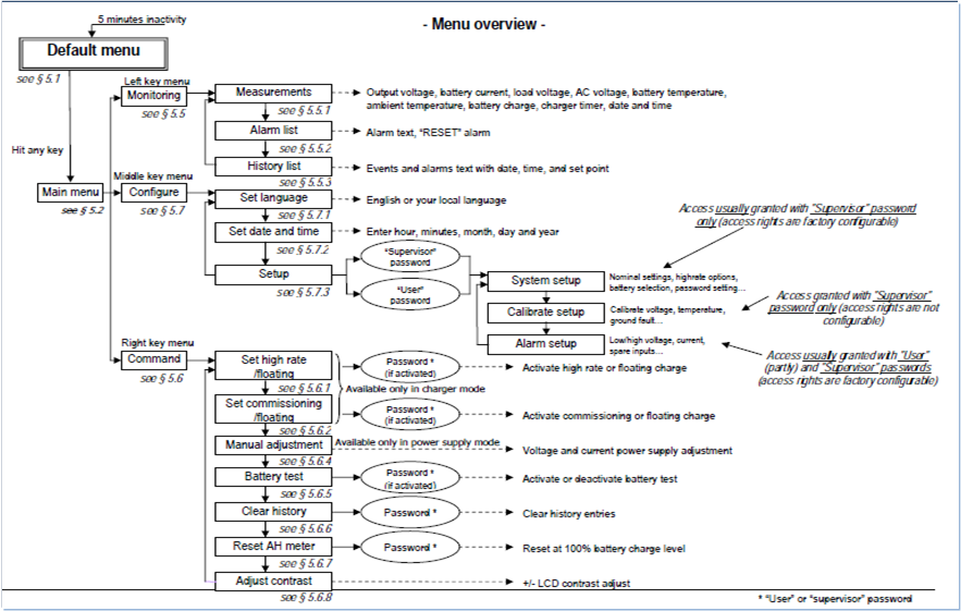
UPS Monitoring Procedure
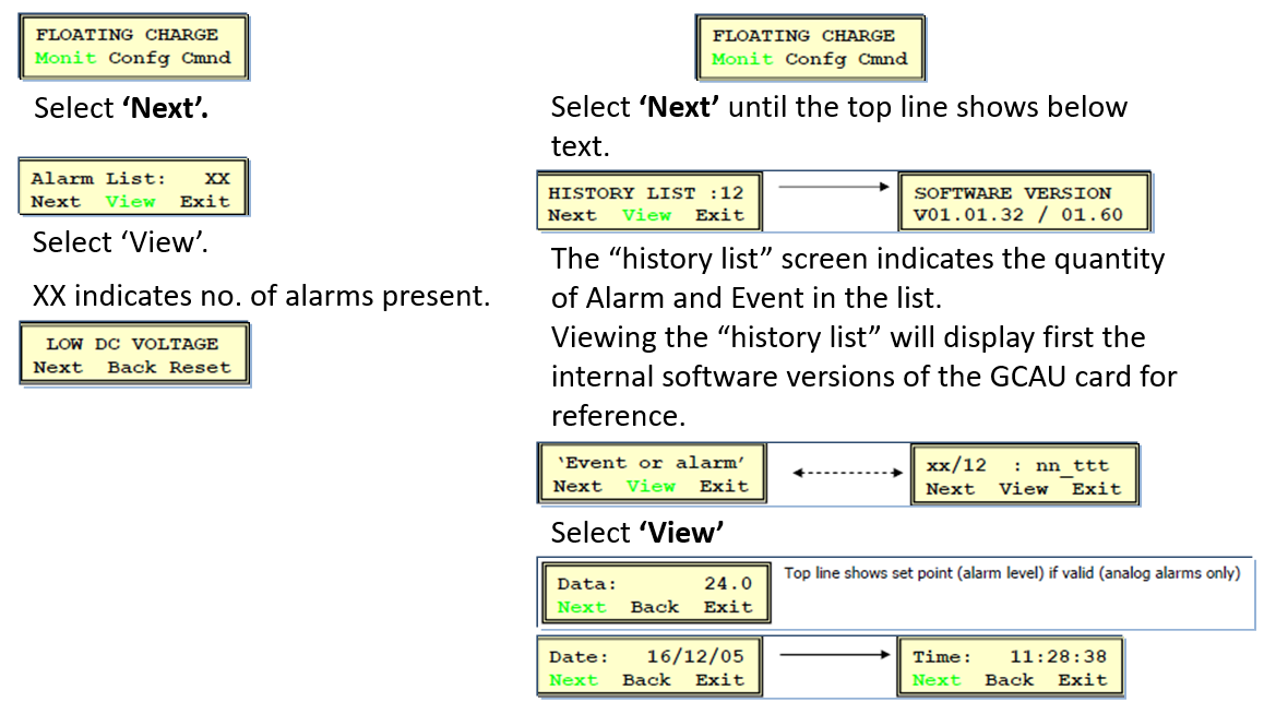
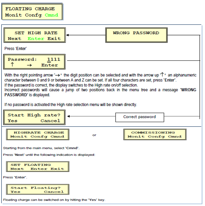
Select ‘View’.
The top line (“Outp”) will display the battery voltage and the total charger current (battery + load).
- Load voltage and current
- Battery current (charge and discharge)
- Battery voltage and total charger current
- AC input voltage
- Battery temperature
- Ambient temperature
- AH Meter
- Remaining charge time (if in High rate or Commissioning charge)
- Date and Time
UPS Alarm List & History List
UPS Charge Mode
DC UPS Operating Procedure
Battery Charger Shutdown
| Step | Action |
| 1 | Verify BC-661K001A & B are operating healthy. |
| 2 | Verify charger-A & charger-B DC switches in DCP-661K001 are in close position.
Verify Battery switch in DCP-661K001 is in close position. |
| 3 | Momentary initiate & disable boost charging of the battery bank by enabling boost charge from BC-661K001B charger menu.
This is to ensure healthiness of battery circuit & Charger –B circuit. |
| 4 | Open DC output switch in charger, BC-661K001A.
Ensure 100% load transfer to BC-661K001B. |
| 5 | Open AC switch in charger, BC-661K001A |
| 6 | Ensure turning off of charger BC-661K001A by reading I/P & O/P voltage. |
| 7 | Open AC Switch in EMCC-661H001-2D & then remove fuses from the circuit. |
| 8 | Open charger-A DC switch in DCP-661K001 & then remove fuses from the circuit. |
| 9 | Ensure charger, BC-661K001A, clearing by following a charger BC-661K001A clearing procedure. |
| 10 | Satisfy the requirements of the Lock-Out/Tag-out process on AC switch in EMCC-661H001-2D and charger- A DC switch in DCP-661K001. |
Battery bank Shutdown
| Step | Action |
| 1 | Verify BC-661K001A & B are operating healthy. |
| 2 | Verify charger-A & charger-B DC switches in DCP-661K001 are in close position. |
| 3 | Ensure DC switch for load unit connection in DS-BC-661K001A is open. |
| 4 | Connect Mobile battery bank at the terminals for load unit with required precaution. This is required for ensuring uninterrupted supply to critical load in case of Charger failure. |
| 5 | Open battery DC switch in, DS-BC-661K001A. |
| 6 | Close load unit DC switch in DS-BC-661K001A |
| 7 | Time period between disconnections of a battery bank BAT-BC-661K001 and connection of mobile battery bank should be very less. |
| 8 | Open one cell’s interconnecting links for battery BAT-BC-661K001 for isolating battery bank. |
| 9 | Ensure floating voltage across battery terminal +ve to Earth & -Ve to Earth.
This is to be checked for ensuring isolation of battery bank. |
| 10 | Perform voltage test at battery connection terminal in DS-BC-661K001A to ensure isolation of these terminals. |
| 11 | Remove fuses from the circuit for battery DC switch in, DS-BC-661K001A. |
| 12 | Ensure battery, BAT-BC-661K001, clearing by following a battery BAT-BC-661K001 clearing procedure. |
| 13 | Satisfy the requirement of the Lock-Out/Tag-out process on Battery DC switch in DS-BC-661K001A. |
Battery Charger & battery bank clearing
| Step | Action |
| 1 | Verify BC-661K001A is shutdown.
Verify AC input switch in BC-661K001A is in the OFF position. Verify DC output switch in BC-661K001A is in the OFF position. |
| 2 | Verify charger-A DC switch in DCP-661K001 is in open position and fuses are removed from the circuit. |
| 3 | Verify AC switch in EMCC-661H001-2D is in open position & fuses are removed from the circuit. |
| 4 | Open door to BC-661K001A to access TB-X1:1, 2, 3 to perform voltage checks. |
| 5 | Perform voltage checks to verify the absence of AC voltage on terminals 1 (L), 2 (N), and 3 (G) on TB-X1 in BC-661K001A. |
| 6 | Perform voltage checks to verify the absence of DC voltage on terminal X3 1 (+) and 2 (-) on in
BC-661K001A. |
| 7 | Satisfy the requirements of the Lock-Out/Tag-out process on AC switch in EMCC-661H001-2D and DC Breaker #1 in DCP-661K001. |
| Step | Action |
| 1 | Verify battery DC Switch in DS-BC-661K001A is in open position & fuses are removed from the circuit. |
| 2 | Perform voltage checks to verify the absence of DC voltage on terminal (+Ve) to Earth and (-Ve) to Earth on BAT-BC-661K001. |
| 3 | Satisfy the requirements of the Lock-Out/Tag-out process on battery DC Breaker in DS-BC-661K001A. |
Battery Charger start up
| Step | Action |
| 1 | Satisfy the requirements for removal of Lock-Out/Tag-out process on AC switch in EMCC-661H001-2D and charger-A DC switch in DCP-661K001. |
| 2 | Verify BC-661K001 B is operating healthy. |
| 3 | Test & Restore fuses & close charger-A DC switch in DCP-661K001. |
| 4 | Test & Restore fuses & Close AC switch in EMCC-661H001-2D. |
| 5 | Close input AC switch in charger, BC-661K001A |
| 6 | Ensure DC voltage at the charger output from front display. |
| 7 | Close O/P DC load switch in charger, BC-661K001A |
| 8 | Verify charger-A & charger- B DC switches in DCP-661K001 are in close position.
Verify Battery switch in DCP-661K001 is in close position. Verify current sharing between BC-661K001A & BC-661K001B. |
Battery Bank startup
| Step | Action |
| 1 | Satisfy the requirements for removal of Lock-Out/Tag-out process on battery DC Switch in DS-BC-661K001A. |
| 2 | Open one of the battery cells interconnecting links for isolating battery bank. |
| 3 | Perform voltage test at battery connection terminal in DS-BC-661K001A to ensure isolation of these terminals. |
| 4 | Test & Restore fuses for battery DC switch in, DS-BC-661K001A. |
| 5 | Restore opened cell’s interconnecting link for battery BAT-BC-661K001. |
| 6 | Open load unit DC switch in, DS-BC-661K001A. |
| 7 | Close battery DC switch in DS-BC-661K001A |
| 8 | Ensure proper isolation of the mobile battery bank & remove it from the service. |
| 9 | Time period between disconnections of a mobile battery bank and connection of battery bank BAT-BC-661K001 should be very less. |
| 10 | Verify charger-A & charger-B DC switches in DCP-661K001 are in close position.
Verify Battery switch in DCP-661K001 is in close position. Verify current sharing between BC-661K001A & B |
Monthly Checks as per S7M-1211-A
| Inspect | Items | Corrective Action |
| VFD or ASD or UPS or Battery Charger (6)
|
For each VFD / ASD / UPS / Battery Charger, check if deficient:
___Unusual Noises ___Rust/evidence of water ___Surface dirt/contamination ___Indicator lights out ___Meter indications faulty ___Alarm indications ___Heating / discoloration. ___Door open and not secured. ___Trash or items stored on or against. ___ Restricted/dirty ventilation filters. ___Inoperative / noisy Fans / Blowers.
___UPS on bypass (UPS only, should be on inverter source)
___DC ground (6) |
If authorized, clean outside surfaces. Use caution and awareness to avoid circuit breaker or switch inadvertent operation.
Resolve any alarm conditions.
If authorized, replace indicator lamps.
If authorized, close and secure doors.
If authorized, clean/replace filters.
Write WO request for repairs or cleaning. |
| DC batteries
Caution: Flammable Hydrogen gas, electric shock and acid hazards. Wear PPE or view from behind equipment barriers. Do not contact the batteries. |
Check if deficient:
___Electrolyte /acid leaks, ___Low Electrolyte level, ___Terminal corrosion ___Internal / external damage. ___ Barriers / guards missing or broken. ___Ventilation systems restricted or inoperative. ___Broken/damaged flame arrestors |
Write WO request for battery service and/or for repairs. |
Quarterly Checks as per S7M-2120-00
| Step | Service | Action | P/PM
on-line |
ACC TST |
| 1 | VOLTST | Check charger volts and amps at battery terminals. (Do not adjust voltages without prior approval from the plant SME ) | n | n |
| 2 | VOLTST | Measure Charger, Battery & Load voltages, both float and equalize if applicable. Adjust the charger output voltage(s) to match battery manufacturer specs. Measure individual cell voltages. Measure ripple voltage and current of the battery system. Limiting values are as follows
Voltage Regulation : ± 1.0% Current Limit : £ 115% Ripple Voltage: < 2 % , Where % = AC (RMS) component/ DC x 100. |
n | n |
| 3 | GROUND | Check positive and negative volts to ground | n | n |
| 4 | SPCGRV | Measure electrolyte level & specific gravity for every cell. Verify proper specific gravity on any cell with V/C reading out of spec. | n | n |
| 5 | CELL CK | Verify temperatures readings on every tenth cell | n | n |
| 6 | GROUND | Battery rack ground connections OK | n | n |
| 7 | REPORT | Send inspection report to site and business SME’s | n | n |
| 8 | REPORT | Extract data into Excel format send to the site SME. | n | n |
| 9 | INFRED | Perform an infrared scan of charger unit for identifying hot spot or any abnormality. | n | n |
| 10 | FUNTES | Ensure load sharing between both chargers. | n | n |
| 11 | CLN | Ensure proper cleanliness inside the charger cabinet. Ensure proper mounting of all components inside the charger panel. | n | n |
Annual Checks as per S7M-2120-00
| Step | Service | Action | P/PM
on-line |
ACC TST |
| 1 | TORQUE/DUCTOR | Check tightness of cable and/or bus connections. Check intercell link integrity per manufacturer instructions. Measure intercell resistance using micro-ohmmeter. Any measurement should be within 20% of the average of all connections, and not exceed 100 micro-ohms. Intercell connectors should be coated with oxide-inhibiting grease. | n | n |
| 2 | REPORT | All test forms and data sheets are to be submitted to the appropriate authority for entry into GEMTS. | n | n |
| 3 | REP | Issue additional work orders as necessary to make additional repairs. | n | n |
Offline inspections as per S7M-2120-00
| Step | Service | Action | P/PM off-line | ACC TST |
| 1 | PREP | Verify a recent annual inspection prior to step 2. | n | |
| 2 | CAPTST | Perform a battery capacity. Percent capacity @ 25°, C = Ta /Te x 100.
Ta = Actual time of test to specified voltage. Te = Rated time to specified voltage. |
n | □
|
| 3 | INFRED | Perform an infrared scan of intercell linkages while executing step 2.
ªTemperature gradients of 1 – 3 ° C indicate possible problems and warrant investigation. ªTemperature gradients of 4 – 15° C require repair as time permits. Temperature gradients of 16° C or more indicate major problems. Remove from service and repair ASAP. |
n |
□ Note 2 |
| 4 | AMPTST | Verify proper charging rates during recharge after step 2. | n | n |
| 5 | CLN | Clean charger cubicle after de-energization | n | n |
| 6 | FUNTES | Confirm proper operation of the charger control circuits. Verify proper operation of the following alarms and that they are annunciating in a manned location.
ªOver/Under Voltage ªGround Fault ªDC output failure ªCurrent Limit Set-point ªAC Input Failure |
n
Note 3 |
n |
| 7 | REPLACE | Replace fans, capacitors, control boards, and power supplies as recommended by the manufacturer and/or site SME. | n | |
| 8 | REPORT | All test forms and data sheets are to be submitted to the appropriate authority for entry into GEMTS. | n | n |
| 9 | REP | Issue additional work orders as necessary to make additional repairs. | n | n |
UPS Safety Points
- Any operation to be done by authorized person only.
- Allow no flame or sparks in the battery room. Never smoke in the battery room. Never disconnect a battery being charged.
- To handle the electrolyte, use gloves and safety goggles.
- The electrolyte contained in a battery is dangerous to the skin and clothing.
- Before doing work on a battery, make sure that there is an accessible supply of water nearby. If electrolyte is splashed, wash immediately with water.
- Use tools with insulated handles.
- Do not place or drop metal objects onto the battery.
- Remove rings, wristwatch and metal articles of clothing that might come into contact with the battery terminals.
Tools & PPEs
- Thermometer.
- Hydrometer.
- Funnel.
- Torque Wrench.
- Voltmeter.
- Temperature Scanner.
- Hard Hat.
- Full body Overall for Acid handling.
- Goggles.
- PVC gloves.
- Hand gloves.
- Face-Shield.
