1. SCOPE…………………………………………………………2. REFERENCES
3. DEFINITIONS
4. DESIGN OF SEWER AND DRAINAGE SYSTEMS 4.1
System Design
4.2
Design
Considerations
4.3
Storm Water Sewer …………………………………..
4.4
Sanitary Sewer
4.5 Oily Water Sewer
4.6
Chemical (Industrial Process) Sewer …………..
4.7 Open
Drainage
Ditches
4.8 Sewer
System
Appurtenances
5. QUALITY CONTROL …………………………………….6. SUBMITTALS
7. SAFETY
8. ENVIRONMENTAL REQUIREMENTS ……………..9. MATERIALS SELECTION
9.1 General
9.2
Pipes and Joints ………………………………………..
9.3
Frames and Covers for Manholes and Sumps
9.4 Grating Cover for Ditches and Catch Basins
10. EXECUTION ………………………………………………..10.1 Receiving, Handling, and Storage
10.2 Trench Excavation
10.3 Dewatering
………………………………………………
10.4 Bedding
10.5 Pipe Laying and Jointing
10.6 Backfilling
…………………………………………………
10.7 Testing and Inspection
11. REVISION HISTORY
1. Scope
This specification is for the design, material selection, installation and testing of gravity sewer systems,
open gravity drainage systems, and sewer appurtenances.
2. References
Reference is made in this specification to the following documents. The latest issues, amendments, and
supplements to these documents shall apply unless otherwise indicated.
SABIC Engineering Standards (SES)
B51-S01 Cast-In-Place Reinforced Concrete
C02-S02 Excavation and Backfill Specification
American Society for Testing and Materials (ASTM)
A 36 Specification for Carbon Structural Steel
A 48 Specification for Gray Iron Castings
A 53 Specification for Pipe, Steel, Black and Hot Dipped, Zinc Coated Welded and Seamless
A 123 Specification for Zinc (Hot-Dip Galvanized) Coatings on Iron and Steel Products
A 569 Specification for Steel Carbon (0.15 Maximum, Percent), Hot-Rolled Sheet and Strip Commercial
Quality
A 786 Specification for Rolled Steel Floor Plates
C 14 Specification for Concrete Sewer, Storm Drain, and Culvert Pipe
C 76 Specification for Reinforced Concrete Culvert, Storm Drain, and Sewer Pipe
C 425 Specification for Compression Joints for Vitrified Clay Pipe and Fittings
C 443 Specification for Joints for Circular Concrete Sewer and Culvert Pipe, Using Rubber Gaskets
C 478 Specification for Precast Reinforced Concrete Manhole Sections
C 700 Specification for Vitrified Clay Pipe, Extra Strength, Standard Strength, and Perforated
C 969 Practice for Infiltration and Exfiltration Acceptance Testing of Installed Precast Concrete
Pipe Sewer Lines
D 422 Test Method for Particle-Size Analysis of Soils
D 1248 Specification for Polyethylene Plastics Molding and Extrusion Materials
D 1556 Test Method for Density and Unit Weight of Soil in Place by the Sand-Cone Method
D 1557 Test Method for Laboratory Compaction of Soil Using Modified Effort (56,000 ft-lbf/ft3
(2,700 kN-m/m3
))
D 1785 Specification for Poly (Vinyl Chloride) (PVC) Plastic Pipe, Schedules 40, 80, and 120
D 2103 Specification for Polyethylene Film and Sheeting
D 2564 Specification for Solvent Cements for Poly (Vinyl Chloride) (PVC) Plastic Piping Systems
D 2855 Practice for Making Solvent-Cemented Joints for Poly (Vinyl Chloride) (PVC) Pipe and Fittings
D 3212 Specification for Joints for Drain and Sewer Plastic Pipes Using Flexible Elastomeric Seals
D 3262 Specification for ‘Fiberglass’ (Glass-Fiber-Reinforced Thermosetting-Resin) Sewer Pipe
D 3350 Specification for Polyethylene Plastics Pipe and Fittings Materials
D 3517 Specification for ‘Fiberglass’ (Glass-Fiber-Reinforced Thermosetting-Resin) Pressure Pipe
D 3839 Practice for Installation of ‘Fiberglass’ (Glass-Fiber-Reinforced) Thermosetting Resin Pipe
D 4161 Standard Specification for ‘Fiberglass’ (Glass-Fiber-Reinforced Thermosetting-Resin) Pipe Joints
Using Flexible Elastomeric Seals
American Petroleum Institute (API)
Manual on Disposal of Refinery Wastes
Occupational Safety and Health Administration (OSHA) of U.S.A.
29CFR 1910 and 1926 Occupational Safety and Health Standards
Royal Commission for Jubail and Yanbu
Engineering Manual
Environment Regulation Conservation Document (ERCD) 9th Nov. 1996
Saudi Arabian Standards Organization (SASO)
Industrial Safety and Health Regulations
3. Definitions
Catch Basin. An open device used at a single point to collect surface drainage with a fire seal (liquid seal)
and sediment trap.
Chemical (Industrial Process) Wastewater. Wastewater containing any raw material,
intermediate/finished product, by product, waste product and chemical substances, for example acids and
alkalies.
Cleanout. A piping connection in a sewer system that is located at grade level for inspecting and cleaning
the system.
Ditch (Trench). A three sided trough located in the ground.
Funnels (Drain Hubb). An open pipe connection located above grade level to collect drips or discharges
from pump bases, piping, sample draw-off points, and equipment drains.
Laterals. Drain lines collecting wastewater from two or more sublaterals and discharging into a sewer
main.
Lift Station. An underground structure, for example, a sump, with a pump used to pump wastewater to a
higher elevation.
Manholes (Junction Boxes). An access point to a sewer system line.
Oily Water. Wastewater generated during the industrial process that contains oil, emulsified oil, or other
hydrocarbons.
Sanitary Wastewater. Wastewater from domestic sanitary sources.
Sewer Main. A system of primary drain lines that collects wastewater from sublaterals and laterals and
conveys it to a point of treatment/discharge.
Stormwater. Consists of rainwater runoff and drainage.
Sublaterals (branches). Lines collecting drains and catch basins that tie into laterals or sewer main.
Sumps. An open or covered basin that serves as a collection point for wastewaters.
4. Design of Sewer and Drainage Systems
4.1 System Design
4.1.1 The system design shall include segregation of wastes, oil recovery, sludge disposal, chemical
wastes, biological and chemical treating, and other disposal problems.
4.1.2 The sewer and drainage systems shall be designed to be free flowing, to collect and convey all
wastewater to their final disposition, and to prevent fire hazards from spreading from one area to another.
4.1.3 Different types of wastewaters shall be segregated, to reduce the size, complexity, and costs of any
treatment facility which shall be required for managing these wastewaters before final discharge from the
site.
4.1.4 The system design of commonly used sewer and drainage systems, for example storm water sewer,
sanitary sewer, oily water sewer, and chemical (industrial process) sewer are detailed in 4.4 to 4.7. The
system design details for open drainage ditches are given in 4.8.
4.2 Design Considerations
4.2.1 Design considerations shall include incompatibility of wastewaters, wastewater volumes and flows,
fire protection and loss prevention, area topography, depth of excavation, pumping requirements, and final
disposition.
4.2.2 The sewer and drainage systems shall be able to convey the volumes of stormwater, sanitary
wastewater, oily water, chemical (industrial process) wastewater and firewater that are expected during the
operation of the facility. The quality of each wastewater stream shall be determined, and each stream shall
be segregated.
4.2.3 Sewer systems shall not be designed to operate in flood conditions. Sewer and drainage systems
shall be designed to operate principally by gravity. Pipes shall be at levels and gradients that ensure
liquids are not retained in any part of the drain system other than in various traps.
4.2.4 Allowances shall be made for future expansion in sewer designs where expansions can be foreseen
and justified.
4.2.5 Waste water at the point of discharge shall conform to ERCD of Royal Commission (RC).
4.2.6 Sewer modeling shall be done by approved computer programs. These specialized programs utilize
comprehensive site specific flowrate calculations to enable determination of accurate sizing.
4.2.7 Sewer shall be sized to operate within its minimum self cleaning velocity and maximum velocity at
design flow. The maximum velocity of flow in sewers shall be 2.1 m/s.
4.2.8 The minimum line size for any single sublateral shall be 100 mm, for ease of cleaning. For lateral
sewer containing flow from two or more sublaterals, the minimum line size shall be 150 mm, and for sewer
header (main) shall be 200 mm, for ease of cleaning.
4.2.9 Sewer lines shall have a minimum earth cover depending on their location. Cover shall be measured
from finished surface to top of pipe. Minimum earth cover in paved area (either concrete or asphalt, where
there is no traffic) and in tank area surrounded by fire dikes, shall be 0.50 m. Earth cover in unpaved areas
shall be minimum 1.0 m.
4.2.10 Earth cover for sewer lines in vehicle traveled areas shall be determined considering the imposed
loads and pipe strength. Following protection methods shall be adopted:
a. Pipe shall be encased in concrete
b. Pipe shall run through sleeve with an inside diameter providing 75 mm total clearance
c. Pipe shall be covered by a concrete slab
4.2.11 Manhole covers shall be removable. The type of sewer shall be embossed in Arabic and English.
4.3 Storm Water Sewer
4.3.1 This system is composed of area drains, catch basins, ditches, culverts, and piping. Storm water,
fire water, and surface water from non-contaminated area shall be collected either into piping or open
drainage ditches. The open ditches shall be used as outlined in 4.8.
4.3.2 This sewer system does not require any treatment, therefore, shall be discharged directly to existing
Royal Commission open ditch system. The open ditch system shall be equipped with water gates at the
discharge point to the Royal Commission open ditch.
4.3.3 Sewers shall be able to discharge the maximum one hour rainfall expected once in ten years without
accumulating a static head at the entrance to the sewer.
4.3.4 Minimum design flow velocity shall be 0.9 m/s (3 ft/s).
4.3.5 Sewers shall be designed to flow 3/4 full.
4.4 Sanitary Sewer
4.4.1 This system is composed of drains, manholes, lift stations, and piping. Sanitary waste-water from
buildings shall be connected to settling tank through a manhole provided for buildings. Sanitary waste
water shall be treated at settling tanks which shall be placed close to each building or in a building area.
The water after sedimentation at the settling tanks shall be transferred to a connection pit and then be
pressurized to go to the Royal Commission sanitary water system. If required, sanitary waste water shall
be pumped through lift station to Royal Commission Sanitary water system.
4.4.2 Minimum design flow velocity shall be 0.6 m/s (2 ft/s).
4.4.3 Sewers shall be designed to flow 1/2 full.
4.4.4 The main sanitary sewer line shall be designed for maximum design flow rate.
4.4.5 Sanitary sewers shall not receive discharges from other sources.
4.4.6 Sanitary sewers shall not be laid in the same trench with potable water lines. At crossings, potable
water pipes shall be installed at the minimum depth of 300 mm above any sanitary sewer pipe.
4.5 Oily Water Sewer
4.5.1 This system is composed of funnels, catch basin, sumps, lift stations, manholes, and piping. Rain
water, fire water, surface water in oil contaminated areas, and oil and oily water from equipment shall be
collected in oily water sewer system through funnels and catch basins.
4.5.2 Oil contaminated areas are classified and paved as follows:
a. Areas where heavy hydrocarbons (C5 and heavier) that will not evaporate at ambient conditions
are present, water soluble chemicals are handled, and an oil spill is anticipated during normal
maintenance, shall be paved and curbed
b. Areas where light hydrocarbons (C4 and lighter) and other chemicals that will evaporate at
ambient conditions are present shall be sloped toward the storm water catch basins
4.5.3 Oily sewer system shall be connected to a holding pond which retains oily water before being treated
in an oil separator or any SABIC approved neutralization system. The oil separator shall be designed in
accordance with API ‘Manual on Disposal of Refinery Wastes’. In case of fire, however, overflow from the
holding pond to a storm water sewer system shall be allowed. Treated water shall be discharged to the
Royal Commission industrial waste water system.
4.5.4 The size of oily water sewers shall be based upon the maximum flow of oily water plus storm water,
or the maximum flow of oily water plus fire water, whichever quantity is greater. However, minimum design
flowrate for oily water sewer for any single fire risk area shall be 32 L/s (500 gpm).
4.5.5 Minimum design flow velocity shall be 0.9 m/s (3 ft/s).
4.5.6 Sewers shall be designed to flow 3/4 full.
4.5.7 Sealing of sewer pipe shall usually be provided with submerging inlet pipes by 150 mm at manholes
and catch basins.
a. Sealing at Manholes
(i) All incoming pipes from catch basins or funnels shall be sealed
(ii) At least one sealing shall be provided for every three consecutive manholes. But at manholes
where two or more inlet pipes join, all inlet pipes shall be sealed.
b. Sealing at Catch Basins. All inlet pipes at catch basins, whether or not the pipes connect with
another catch basin or funnel, shall be sealed.
4.6 Chemical (Industrial Process) Sewer
4.6.1 Chemical sewerage shall be treated depending on the nature of the chemical substances contained
in the water. If the chemical sewerage is not treated, it shall be collected in pits or tanks and periodically
hauled away by vacuum trucks for safe disposal conforming to the requirements of Royal Commission.
4.6.2 Design of chemical sewer shall be based on the maximum design flow rate.
4.6.3 Minimum design flow velocity shall be 0.6 m/s (2 ft/s).
4.6.4 Chemical sewer shall be designed to flow
3/4 full.
4.6.5 Bottom of manhole shall be 600 mm below the inlet. Inlet shall have a 300 mm liquid fire seal.
4.7 Open Drainage Ditches
4.7.1 Drainage ditches shall be used inside and outside of process unit battery limit. They are used to
collect stormwater, firewater and surface water from non-contaminated area.
4.7.2 Drainage ditches shall not receive oily water.
4.7.3 The location and design of drainage ditches relative to process equipment and piping shall be
carefully considered to prevent the spread of fire. Fire stops shall be provided where deemed applicable.
4.7.4 Drainage ditch size shall be calculated on the basis of flowing full plus 150 mm of free board.
4.7.5 The minimum slope of the ditch shall be minimum 1 mm/m, and minimum velocity shall be 0.3 m/s.
The maximum velocity shall be 2.1 m/s.
4.7.6 Drainage ditches shall be separated from pipeways by a minimum horizontal distance of 3 m and
from process equipment by 10 m minimum. Where overhead and abovegrade hydrocarbon, firewater, or
utility lines cross over, or if they are within 5 m of open drainage ditches, the overhead lines shall be
continuous pipe or welded joints. Pipe flanges or threaded connections or fittings shall be prohibited.
Pipeways crossing or within 5 m of drainage ditches shall be protected from fire by a concrete slab,
culvert, or by fireproofing the piping. Fireproofing shall have a 1 hr fire rating.
4.7.7 Ditches shall be constructed of reinforced concrete in accordance with design drawings.
4.7.8 For concrete-lined ditches, side slopes shall be stable without the lining, unless the lining is
designed to withstand resulting soil pressures.
4.7.9 A vapor barrier of polyethylene sheet shall be provided under the concrete ditches. The sheet shall
conform to ASTM D 2103, with a minimum thickness of 200 µm.
4.8 Sewer System Appurtenances
4.8.1 Manholes
a. Manholes shall be provided for the following conditions:
(i)
Immediately outside a process unit area
(ii) Where sewer mains change direction abruptly and more than 15°
(iii) Where laterals connect to a sewer main
(iv) Where sewer size changes
(v) Where there are abrupt changes in elevation
b. The inside diameter or side of manholes shall be 1.22 m minimum.
c. Manholes shall be pre-cast concrete conforming to ASTM C 478 or poured-in-place concrete
type conforming to SES B51-S01. Manholes shall be waterproofed on the exterior. Inlet and outlet
pipes shall be joined to the manhole with a watertight connection arrangement. Waterstop shall be
provided at construction joints for poured-in-place manholes.
d. The interior of oily water and chemical water manholes shall have a protective coating. The
coating shall be resistant to oil and chemicals.
e. Fire seals shall be provided on all inlet lines to a manhole that may contain flammable fluids,
unless otherwise specified in design drawings.
f. Manholes shall be designed for straight-through flow.
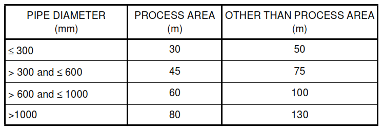
g. The maximum spacing of manholes shall be as follows:
h. The manhole covers, where flammable, toxic, or bad smelling vapors arise, shall be tight.
Leakage of these vapors shall be prohibited. The manhole cover shall pass the load test as follows:
(i) Walking areas – 150 kN
(ii) Light traffic and car parking areas – 400 kN
(iii) Heavy traffic areas – 600 kN
i. All manhole covers shall be removable.
j. The internal size of a manhole cover shall not be less than 600 mm. Checkered-plate shall be
stiffened at the bottom to withstand the desired load.
k. The top of manholes shall be flush with pavement, but project 50 mm from the grade in unpaved
areas
l. Steel climbing rungs – 20 mm diameter, distance from wall – 150 mm, rung spacing – 330 mm,
shall be provided in manholes deeper than 1 m, in accordance with design drawing.
4.8.2 Catch Basins
a. Catch basins shall be designed to collect and convey the full catchment area design flow without
flooding of the pavement area. Catch basins shall be kept open to collect spills and storm or firewater.
Openings shall allow maximum flow of 115 m3/h without restriction. Removable gratings shall also be
provided flush to grade, and shall be designed to carry a minimum load of 4.22 kg/cm2 (60 psi). Theoutlet pipe size shall be 150 mm minimum.
b. In process units, no more than 4 catch basins shall be connected with pipe for discharging into a
manhole. Fire seals shall be provided on all inlet lines to catch basins that may contain flammable
liquids. Grating-covered catch basins shall not be located beneath process equipment or pipeways.
They shall be spaced horizontally at least 0.8 m away from pumps and 1.5 m from compressors and
uninsulated vessels containing hydrocarbons. Catch basins shall not be located closer than 10 m to
fired heaters or similar constant ignition sources.
c. The size of all catch basins shall be sufficient to allow maintenance and waterfilling tests to be
easily carried out. The internal size shall be 600 mm minimum.
4.8.3 Cleanouts
a. Sewers shall have cleanouts at dead ends of lateral lines and at points where the line makes a
horizontal change of direction 45° or more, and where the length of pipe is more than 15 m.
b. Cleanouts shall be installed to facilitate cleaning in the direction of the flow.
c. Cleanouts shall have plugs that open in the direction opposite to the flow.
d. Funnels shall be considered as cleanouts if the run to the drain header is less than 6 m, and total
turns do not exceed 135°. This shall include the 90° turn from vertical to horizontal.
e. Cleanouts shall be the same as the line size in sanitary sewers, and shall not exceed 150 mm in
all other sewers.
4.8.4 Vents
a. Manholes and sumps shall be provided with sealed covers and vented to a safe location to avoid
hazards to personnel. The vent shall be minimum 50 mm and shall not exceed 100 mm in line size.
For oily water sewers where flammable vapors may be present, the vent pipe end shall be minimum
of:
(i) 3 m above any adjacent service platform
(ii) 6 m above ground level
(iii) 15 m measured horizontally from any fired heater or other source of ignition
(iv) 5 m from building air intakes or windows
b. For sanitary sewers and sumps, the vent line shall end a minimum of 2 m above grade.
c. Vent pipes shall be designed to drain condensation back to the manhole or sump.
4.8.5 Funnels
a. A funnel shall be provided for each piece of equipment, machinery, or tanks from which oily drain
or chemical drain is discharged.
b. The top of funnels shall project minimum 50 mm above grade in paved areas, and minimum
150 mm in unpaved areas.
c. The pipe connecting funnels should preferably be connected to a manhole rather than a catch
basin.
d. No more than six funnels shall be connected before the connecting pipe enters a manhole or
catch basin.
e. The pipe connecting funnels shall join with other pipe at a manhole or a catch basin, and shall
not join directly with other pipe. Where the pipe connecting funnels join or change directions, the
angle shall be 45° or less.
f. A strainer with a mesh size of not more than 10 mm, shall be provided at the inlet of a funnel. If
the areas where funnels are located are susceptible to accumulate sand or dust, funnels shall be
provided with removable covers. Strainers shall not be required for these funnels.
g.
Inlet diameter of funnel shall be 150 mm minimum.
4.8.6 Lift Stations (Pumping Stations)
a
Lift stations shall be provided where complete routing of gravity sewer systems is not possible.
The lift station shall consist of a concrete sump and either vertical or submersible pumps.
b. The lift stations pumps shall be sized for the maximum design flow. A minimum of two pumps of
the same capacity shall be provided, to give one pump as a spare.
c. The sump shall be readily accessible for maintenance and removal of accumulated grit and
separated oil.
d. The sump shall be covered, and shall include tight seals around the pump entry points.
e. The sump shall be vented with a 100 mm minimum line size to prevent the accumulation of
flammable gases. The vent pipe shall run to a safe location, in accordance with 4.8.4.
4.8.7 Drainage from Diked Area
a. Valve Pit. To isolate a diked area, a valve pit shall be provided outside the diked area. The valve
pit shall be located close to the dike. The valve shall be a gate valve or a butterfly valve.
b. Storm Water
(i) At least one catch basin shall be provided in a diked area, for collecting surface storm water and
fire water. The water collected at the catch basin shall be discharged outside through a valve pit.
(ii) When designing sewer systems outside the diked area, the flow from the diked area shall not be
considered in determining the maximum flow rate.
(iii) The valve shall usually be kept closed, and opened only when the flow of the outside sewer
system is low.
c. Tank Drain. Tank drain shall flow through pipes and shall be discharged outside through the valve
pit. The size of the pipes shall be minimum 150 mm.
4.8.8 Drainage for Fired Heaters. Surface water at and around a fired heater should be collected with
catch basins that are designed to not retain any oil or oily water. If this is not practical, then the catch basins
shall not be installed below, around the periphery, or within 15 m of the fired heaters. However, the catch
basins shall be located midway between the fired heater pairs.
5. Quality Control
5.1 SABIC will inspect all materials and workmanship at its discretion. SABIC will have unrestricted entry
to the fabrication shop. SABIC will reject improper, inferior, or defective materials and workmanship at any
stage of production. All defective materials shall be repaired or replaced as required by SABIC.
5.2 If at any time during installation and testing, weather or any other factor causes the degradation of the
pipe foundation, pipe and fitting installation, bedding, or backfill, all affected materials shall be removed and
re-installed in accordance with this specification, or as directed by SABIC.
6. Submittals
6.1 Fabrication drawings and instructions for the installation of pipe and appurtenances furnished under
this specification shall be submitted to SABIC 30 days before installation.
6.2 Along with the shipment of the materials to be used under the contract, the material supplier or
contractor, or both, shall submit to SABIC, the Certified Material Test Report (CMTR).
6.3 As-built documentation showing location, line, and grade of newly installed sewer systems shall be
submitted to SABIC.
7. Safety
7.1 Sewers covered by this specification shall be fabricated, installed, and tested in accordance with
applicable codes, standards, and procedures specified herein.
7.2 Field construction activities shall conform to SABIC’s safety requirements and to specific site rules.
7.3 Good housekeeping shall be practiced in and around the work site at all times.
7.4 Hazardous and Hot Work Permits for chemical exposure, open flames, spark producing mechanical
equipment, potential explosive mixtures, and any other hazardous conditions shall be required in areas
specified by SABIC.
7.5 All excavation and trenching shall be in accordance with OSHA 29CFR 1910 and 1926, and SABIC’s
local applicable requirements and guidelines for:
a. Shoring, bracing and sloping wall construction
b. Marking and flagging open excavations
c. Safe work permitting and confined space entry requirements
8. Environmental Requirements
8.1 Trench dewatering, testing, or other activities where liquids need to be disposed, and all sewer outfalls
into Royal Commission drains and ditches, shall conform to Royal Commission requirements, and shall
require RC approval.
8.2 Excavated material shall be managed in accordance with the soil management plan which is in place,
or which has been developed by contractor and accepted by SABIC prior to excavation activities, and
which shall be part of the contract documents.
9. Materials Selection
9.1 General
Piping material shall be selected from those specified in 9.2 considering temperature, corrosiveness of
wastewater, soil conditions, pipe joint integrity, imposed loads, durability, and availability.
9.2 Pipes and Joints
9.2.1 Concrete Pipe / Reinforced Concrete Pipe (CP/RCP)
a. 250 mm (10 in) and smaller shall be ASTM C 14 (class as specified on design drawing)
non-reinforced, bell and spigot or tongue and groove sewer pipe.
b. 300 mm (12 in) and larger shall be ASTM C 76M, reinforced sewer pipe, (class as specified on
design drawing).
c. Joints shall be sealed with elastomeric ‘O’ rings, and shall conform to ASTM C 443, unless
otherwise noted on design drawings.
9.2.2 Vitrified Clay Pipe (VCP)
a. Vitrified clay pipe shall be of extra strength, in accordance with ASTM C 700.
b. Joints shall be compression type, in accordance with ASTM C 425, unless otherwise specified
on the engineering drawings.
9.2.3 Polyvinyl Chloride Plastic (PVC) Pipe
a. 300 mm (12 in) or less diameter shall be PVC schedule 40 Pipe conforming to ASTM D 1785.
b. Joints shall be solvent cemented in accordance with ASTM D 2855, and the cement in that
solvent shall be in accordance with ASTM D 2564. Alternatively the joints shall be elastomeric ring
gasket conforming to ASTM D 3212.
9.2.4 High Density Polyethylene (HDPE)
a. Pipe and fittings shall be manufactured from virgin high density polyethylene resin, in
accordance with ASTM D 3350, Cell Class PE345434C minimum, with a Standard Dimension Ratio
(SDR) as specified on the engineering drawings.
b. Joints shall be butt fusion welded or flanged.
9.2.5 Carbon Steel Pipe
a. Pipe shall conform to ASTM A 53, Grade B.
b. Pipe shall be externally coated, wrapped and cathodically protected.
c. Carbon steel pipe shall not be used for sanitary sewers or corrosive chemical sewers.
9.2.6 Fiberglass (Glass-Fiber-Reinforced Thermosetting-Resin) Pipe (RTRP)
a. Pipe and fittings shall conform to ASTM D 3262 and D 3517.
b. Joints shall conform to ASTM D 4161.
9.3 Frames and Covers for Manholes and Sumps
9.3.1 Manhole and sump frames, covers, and gratings, shall be cast iron, shall conform to ASTM A 48, and
shall be bituminous painted.
9.3.2 Cast iron covers for storm water sewer manholes and sumps may be substituted by precast concrete
construction, conforming to SES B51-S01, or checkered plate conforming to ASTM A 786 and A 36 and
galvanized in accordance with ASTM A 123.
9.3.3 HDPE plate used for manholes and sumps shall be manufactured from virgin high density
polyethylene resin in accordance with ASTM D 1248 for IIIC5-P34, pipe grade resin.
9.4 Grating Cover for Ditches and Catch Basins
The grating cover shall be welded steel bar grating conforming to ASTM A 569, and galvanized in
accordance with ASTM A 123.
10. Execution
10.1 Receiving, Handling, and Storage
10.1.1 Proper care and protection shall be provided during receiving, handling and storage of pipe
materials, to prevent damage, stresses or deformation of pipe materials.
10.1.2 Prior to installation, pipe materials shall be inspected. Rejected materials shall be replaced.
10.2 Trench Excavation
10.2.1 All excavation and trenching shall be in accordance with SES C02-S02 and 7.5 of this specification
respectively.
10.2.2 Proper care and protection shall be provided to prevent damage to all existing facilities, for example
foundations, services, and pipelines, on, above or below the surface of the area where excavation and
backfill operations are to be performed. Underground obstructions, for example piping, foundations, and
structures, shall not be removed or altered without SABIC approval.
10.2.3 Trench depths shall be as required by design and shown on design drawings. Trench shall be
excavated to a minimum width sufficient to allow satisfactory bedding and jointing of pipe and tamping of
backfill under and around pipe. The trench width shall be as the external pipe diameter plus 500 mm for
pipes up to 760 mm (30 in) and external diameter plus 700 mm for larger pipe.
10.2.4 As a result of existing soil conditions, the trenches might cave in or slide, therefore, they shall be
shored or constructed with slopes. The inclination of the slopes will depend on the soil properties. Where
no soil characteristics have been provided, the following maximum angles of slope will be permitted:
a. Non-cohesive or soft-cohesive soil 45°
b. Stiff, cohesive soil 60°
c. Soft rock 70°
d. Heavy rock 90°
10.2.5 Where rock or other unyielding material is encountered, the bottom of the trench shall be over
excavated 100 mm, and the over-excavation portion shall be backfilled with load bearing dune sand to line
and grade.
10.2.6 Where unacceptable soil is encountered, as determined by SABIC, it shall be removed. The
resulting over-excavation shall be backfilled with dune sand to line and grade.
10.2.7 As applicable, the bottoms of trenches or bedding material shall be graded to provide uniform
bearing of the pipe. Where pipe joint diameter exceeds pipe outside diameter, for example in bell and
spigot piping, bell holes shall be manually excavated after the trench bottom has been graded. This makes
bells and joints absolutely free, and the remaining pipe will rest uniformly over its entire length.
10.2.8 Trenches shall be kept dry as much as possible during bedding, laying, joining, testing and
inspection of the pipe.
10.2.9 Adequate measures shall be taken to prevent erosion and cave-in. Excavated or other material
and equipment shall not be stored within a distance equal to one and a half times the depth of the
excavation.
10.3 Dewatering
10.3.1 Pumps, sumps, suction and discharge lines, and all other dewatering system components
necessary to collect and discharge water away form excavations shall be provided, installed, and
maintained by contractor.
10.3.2 The length of open trench shall be limited at all times to that which can be dewatered with methods
and equipment available.
10.3.3 Dewatering methods shall be used to minimize softening of pipe foundation bottoms, and to avoid
undercutting of footings, and changes in soil characteristics detrimental to subgrade stability.
10.3.4 Water shall not accumulate in excavations. Subsurface water flowing into excavations shall be
removed by pumping or by gravity drainage.
10.3.5 Surface water shall be diverted away from the work area as directed by SABIC.
10.3.6 The trench shall not be used as a temporary drainage ditch.
10.4 Bedding
10.4.1 Bedding material shall be dune sand, well graded, 100 percent passing 12.5 mm (
/2 in) sieve and
at least 90 percent retained on 75 µm (No. 200) sieve as determined in accordance with ASTM D 422.
1
10.4.2 Bedding material shall be placed under the pipe, equally along both sides of the pipe, and up to a
height of 200 mm above the top of pipe. Adequate bedding width and thickness will be designed by
SABIC. It shall be compacted by hand or hand operated pneumatic tampers. Contractor proposed
alternative method may be applied, if approved by SABIC.
10.4.3 Bedding material shall be compacted to the density of the undisturbed site soil materials, or as
specified on design drawings. Compacted pipe bed shall provide uniform bearing for the bottom of the
pipe’s entire length. Trenching shall be in accordance with 10.2.
10.5 Pipe Laying and Jointing
10.5.1 Pipe shall be laid beginning at the lowest point in trenches. Pipes with spigot or tongue ends shall
be laid with spigot ends pointing in the direction of flow. Other pipe types shall be laid in accordance with
manufacturer’s recommendations. Pipe shall be laid true to line and grade, and kept clean and sound.
10.5.2 Where sewer pipe intersects the outside face of a manhole or other type of structural wall, a pipe
joint or wall sleeve shall be constructed to allow flexibility.
10.5.3 Each pipe length shall be inspected for loose gaskets, cracks, and other defects prior to
installation. Inspected pipe length shall be carefully placed to the line and grade specified on design
drawing, and nested in the bedding, to provide uniform support to the entire length.
10.5.4 When pipe laying is suspended, the pipe ends shall be sealed, to keep soil and foreign materials
out.
10.5.5 Joints shall be tight, to minimize infiltration or exfiltration. Testing shall be in accordance with 10.7.
10.5.6 RTRP piping shall be installed in accordance with ASTM D 3839 and manufacturer’s instructions,
and in manufacturer’s presence. In case of conflict(s), conformance to ASTM D 3839 shall prevail.
10.6 Backfilling
10.6.1 All blocking, cribbing, shoring materials, and debris shall be removed from the trench prior to
backfill. Backfill shall be carried out immediately after the pipes have been laid down and bedding is
completed.
10.6.2 Backfill material shall contain no rocks or stones larger than 75 mm (3 in) and shall be free from
lumps, organic matter, trash, and chunks of highly plastic clay.
10.6.3 Backfill which is around and over underground lines laid beneath building foundations, floor, road
pavement, railroads, parking areas, truck turnarounds and paved areas, shall be placed in uniform layers
not exceeding 200 mm (8 in) loose thickness. Each layer shall be compacted to a dry density equal to 95
percent of the dry density obtained by compaction according to ASTM D 1557, Method A (Modified Proctor
Tes t ) .
10.6.4 The remainder of the trench shall be backfilled and compacted to the density specified in the design
drawing, or equal to adjacent in-situ material. Excavated material shall be reused to the extent possible for
this backfill.
10.6.5 Compaction by water jetting or flooding shall not be permitted.
10.6.6 No construction machinery or vehicles shall be allowed to pass over the trench until the trench is
backfilled and compacted, to prevent damage to the pipe.
10.7 Testing and Inspection
10.7.1 In the presence of SABIC, before backfilling the installed sewer system, the following shall be
performed:
a. All debris and sand shall be removed from section of sewers and laterals. A close-fitting mandrel
shall be passed through piping, to ensure that all debris and sand has been removed.
b. Gradient, invert elevation and soundness of joint shall be inspected.
c. System shall be tested in accordance with 10.7.3 for water tightness. Leakage will show cracks in
pipes and faulty joints.
d. After the backfilling, system shall be tested in accordance with 10.7.3 for water tightness.
Leakage shows the fault of pipe bedding or support, or any damage during and after backfilling.
e. Piping that does not conform to any of the above requirements shall be replaced or repaired to
the satisfaction of SABIC.
10.7.2 Wherever possible, testing shall be carried out from manhole to manhole. Short branch drains
connected to a main sewer between manholes shall be tested as one system with the main sewer. Long
branches shall be tested separately from manholes.
10.7.3 Water Test (Exfiltration Test)
a. Drains and sewers shall be subjected to an internal pressure test with a head of water at least
1.5 m above the crown of the pipe at the high end, but not more than 6 m at the low end. A standpipe
shall be employed to obtain the specified head.
b. The test shall start approximately one hour after filling the pipe with water. Water shall be added
to maintain test head to cover water loss due to absorption and air pockets in certain piping
configurations.
c. Measure exfiltration at a manhole. The section of pipe to be tested shall be plugged at the
downstream end of pipe, for example the second manhole. The laterals in the section being tested
shall be plugged with removable stoppers.
d. The loss of water over a period of 30 minutes shall be measured by adding water from a
measuring vessel at 10-minute intervals and noting the quantity required to maintain the original water
level. For this test, the average quantity of water added shall not exceed 1.0 liter per hour per
100 meters linear distance per centimeter of nominal internal sewer diameter.
e. Pipe exfiltration (leakage) that causes a drop in the test water level will be apparent by the
change in the water level in the standpipe. Any leaks visible during water testing shall be repaired.
Defective parts of the sewer system shall be removed, replaced, and retested.
f. The maximum allowable exfiltration (leakage) shall be as follows:
(i) Storm Sewers – 0.00018 L/mm diameter/m/h (0.0039 gallons/in diameter/ft/h)
(ii) Sanitary Sewers – 0.000037 L/mm diameter/m/h (0.0008 gallons/in diameter/ft/h)
10.7.4 Pipe with bell and spigot and mechanical joints shall be anchored, to prevent separation caused by
head pressure.
10.7.5 Exfiltration testing of storm sewers of precast concrete pipe shall be in accordance with
ASTM C 969.
10.7.6 Infiltration test shall be carried out on sewer lines located below the ground water level.
a.
Infiltration test shall be carried out by sealing off all but the discharge end of the sewer being
tested, and measuring the rate of the infiltrated water.
b. The maximum allowable infiltration shall be the same as for exfiltration specified in 10.7.3.f.
10.7.7 The water testing of RTRP piping shall be in accordance with manufacturer’s instructions, and in
manufacturer’s presence.