1. SCOPE …………………………………………………………………….2. REFERENCES 3
3. DEFINITIONS 5
4. GENERAL REQUIREMENTS ……………………………………..5. WORKMANSHIP 5
6. SUBMITTALS 5
6.1 Manufacturer’s Catalog Data……………………………………6.2 Manufacturer’s Instructions 6.3 Sterilization Certificate 6.4 Cathodic Protection ……………………………………………….6.5 Piping Test Record
6.6 Operation and Maintenance Manuals 6.7 Operating Instructions ……………………………………………7. POSTED OPERATING INSTRUCTIONS 8. FINAL INSPECTION AND ACCEPTANCE 9. QUALITY ASSURANCE………………………………………………9.1 Material and Equipment Qualifications 9.2 Alternative Qualifications 9.3 Service Support …………………………………………………….9.4 Product Identification and Labelling 10. PRODUCT DELIVERY AND HANDLING 11. PRODUCTS ……………………………………………………………..11.1 Equipment 11.3 Specialties 11.4 Piping Materials …………………………………………………….11.5 Insulation 11.6 Septic Tank 11.7 Lift Station ……………………………………………………………12. EXECUTION 112.1 Surface Conditions 112.2 Plumbing System Layout ……………………………………….
12.3 Installation of Piping 12.4 Installation of Equipment 12.5 Equipment Access ………………………………………………..12.6 Pipe Joints 112.7 Pipe Supports 112.8 Sleeves and Openings …………………………………………..12.9 Field Wrapping Underground and Under Slab Piping12.10 Cleanouts 12.11 Valves ………………………………………………………………….12.12 Water Hammer Arresters 12.13 Valve and Pipe Identification 12.14 Pipe Identification ………………………………………………….12.15 Plumbing Fixture Installation 13. CLEANING, TESTING AND BALANCE 14. AS BUILT DRAWINGS ……………………………………………….15. ATTACHMENTS 2
1. Scope
1.1 This specification prescribes standards for plumbing systems listed below, complete and ready for
operation, including necessary piping, fittings, valves, hangers and supports, fixtures, equipment,
insulation and other trim, accessories, and related parts.
1.2 Systems included
1.2.1 Sanitary and Storm Sewer DWV (Drainage, waste, and vent)
1.2.2 Laboratory waste and vent (Laboratory)
1.2.3 Laboratory Carrier Gases such as Nitrogen, Hydrogen, Oxygen, and Helium
1.2.4 Utility Piping System such as Steam, Compressed Air, Distilled water, Instrument Air, Plant Air, and
Vacuum
1.2.5 Domestic Hot and Cold Water Supply System
1.2.6 Plumbing Equipment, Fixtures and Specialties
1.2.7 HVAC Equipment Condensate Drainage
1.2.8 Septic Tank, Lift Station and Grease Trap
1.2.9 Eyewash and Safety Shower
1.2.10 Inspection, Testing and System Cleaning
1.3 The following items are excluded from this specification:
1.3.1 Main line of each utility supply up to the connecting point approximately one and one half (1 ½)
meters from each building perimeter.
1.3.2 Main sanitary sewer lines from the manhole to the locations approximately one and one half (1 ½)
meters from each building perimeter.
2. References
2.1 Reference is made in this standard to the following documents. The latest issues, amendments and
supplements to these documents shall apply unless otherwise indicated.
2.1.1 American Refrigeration Institute (ARI)
ARI 1010 Self-contained, Mechanically Refrigerated Drinking Water Coolers
2.1.2 American Society of Mechanical Engineers (ASME)
ASME A13.1 Scheme for the Identification of Piping Systems
ASME A112.18.1M Plumbing Fixture Fittings
ASME A112.19.2M Vitreous China Plumbing Fixtures
ASME B1.3M Screw Thread Gaging Systems for Dimensional Acceptability-Inch and Metric Screw
Threads.
ASME B16.3 Malleable Iron Threaded Fittings Class 150 and 300
ASME B16.22 Wrought Copper & Copper Alloy Solder Joint Pressure Fittings
2.1.3 American Society of Sanitary Engineering (ASSE)
ASSE 1003 Performance Requirements for Water Pressure Reducing Valves
ASSE 1010 Performance Requirements for Water Hammer Arresters
ASSE 1013 Performance Requirements for Reduced Pressure Principle Backflow Preventers
ASSE 1017 Performance Requirements for Temperature Actuated Mixing Valves for Primary Domestic
Use
ASSE 1018 Performance Requirements for Trap Seal Primer Valves Water Supply Fed
2.1.4 American Society for Testing and Materials (ASTM)
ASTM A53 Standard Specification for Pipe, Steel, Black & Hot Dipped Zinc-Coated, Welded & Seamless
ASTM A105 Standard Specification for Carbon Steel Forgings for Piping Applications
ASTM A197 Standard Specification for Cupola malleable Iron
ASTM A234 Standard Specification for Pipe Fittings of Wrought Carbon Steel and Alloy Steel for Moderate
& High Temperature
ASTM A312 Standard Specification for Seamless and Weld Austenitic Stainless Steel Pipes
ASTM A888 Standard Specification for Hubless Cast Iron Soil Pipe and Fittings for Sanitary and Storm
Drain, Waste, and Vent Piping Applinactions
ASTM B36 Standard specification for brass plate, sheet, strip and rolled bar
ASTM B62 Standard specification for Composition Bronze or Ounce Metal Castings
ASTM B75 Standard Specification for Seamless Copper Tube
ASTM B88 Standard Specification for Seamless Copper Water Tube
ASTM B584 Standard specification for copper alloy sand castings for general applications.
ASTM C534 Standard Specification for Preformed Flexible Elastomeric Cellular Thermal Insulation in
Sheet and Tubular Form.
ASTM C547 Standard Specification for Mineral Fiber Pipe Insulation.
ASTM C1277 Standard Specification for Shielded Coupling Joints Hubless Cast Iron Soil Pipe and Fittings.
ASTM D2564 Standard Specification for Solvent Cements for Poly (Vinyl Chloride) (PVC) Plastic Piping
Systems.
ASTM D2665 Standard Specification for Poly (Vinyl Chloride) (PVC) Plastic Drain, Waste, and Vent Pipe
and Fittings
ASTM D4101 Standard Specification for Propylene Plastic Injection and Extrusion Materials
ASTM E84 Standard Test Method for Surface Burning Characteristic of Building Materia
ASTM F656 Standard Specification for Primers for Use in Solvent Cement Joints of Poly (Vinyl Chloride)
(PVC) Plastic Pipe and Fittings
ASTM F1412 Standard Specification for Propylene Pipe and Fittings for Corrosive Waste Drainage
Systems
2.1.5 American Welding Society Inc. (AWS)
A5.8 Specification for Filler Metals for Brazing and Braze Welding
2.1.6 American Water Works Association (AWWA)
C651 Disinfecting Water Mains
2.1.7 Compressed Gas Association (CGA)
G4.1 Cleaning Equipment for Oxygen Service
2.1.8 Industrial Safety Equipment Association (ISEA)
Z358.1 Emergency Eyewash and Shower Equipment
2.1.9 Plumbing and Drainage Institute (PDI)
PDI G101 Standard Testing and Rating Procedures for Grease Interceptors
PDI WH 201 Water Hammer Arrester Standard
2.1.10 Underwriters Laboratories Inc. (UL)
UL 174 Standard for Safety Household Electric Storage Tank Water Heaters
2.1.11 Uniform Plumbing Code
2.1.12 Company Engineering Standards
Z01-D05 Units for Use in Projects
Z01-G03 Metrification
3. Definitions
None
4. Design of Plumbing System and Specification
4.1 Documents, drawings and calculations required by this standard shall use SI units of measure in
accordance with Engineering Standards SES Z01-D05 and Z01-G03.
4.2 Conflicts between this standard, SES, and industry standard, engineering drawings, codes and
contract documents shall be resolved at the discretion.
4.3 Plumbing systems shall be designed in accordance with Uniform Plumbing Code and this
specification.
5. Workmanship
Work shall be performed by craftsman skilled in their particular trade. Systems shall be installed squared
and plumbed and accessible for proper operation and service. Installations shall be consistent in
completeness and appearance whether enclosed or exposed. Any work which will not present a neat
workmanlike appearance shall be reworked at the expense of the contractor.
6. Submittals
Submittals required in other sections which refer to this section shall conform to the requirements of each
specific specification and the following additional requirements; Submittals shall include Manufacturer’s
name, trade name, place of manufacture, catalog model or number, nameplate data, size, layout
dimensions, capacity, project specification and paragraph reference, applicable industry and technical
society reference standards, local codes and other information necessary to establish contract compliance
of each item that supplier proposes to be provided. Photographs of existing installations are unacceptable
and shall be returned without approval.
6.1 Manufacturer’s Catalog Data
Submittals for each manufactured item shall be current Manufacturer’s descriptive of cataloged products,
equipment drawings, diagrams, performance and characteristic curves, and catalog cuts.
6.2 Manufacturer’s Instructions
Where installation procedures or part of installation procedures are required to be in accordance with
Manufacturer’s instructions, printed copies of those instructions shall be submitted prior to installation.
Installation of the item shall not proceed until Manufacturer’s instructions are received. Failure to submit
can be cause for rejection of the equipment or material.
6.3 Sterilization Certificate
Upon completion of water line sterilization, two (2) copies of an acceptable Certificate of Performance for
that activity shall be submitted to the Construction Manager.
6.4 Cathodic Protection
6.4.1 Upon completion of the work of this section, sufficient documentation shall be delivered to the Construction Manager to prove that wrapping of steel piping has been tested and meets the specified
requirements.
6.4.2 Date of inspection, voltages used, name and address of Inspector shall be submitted.
6.5 Piping Test Record
Plumbing lines shall be tested in presence of representative or designee. Upon completion of piping
pressure tests, deliver to the Test Record Forms documenting that activity.
6.6 Operation and Maintenance Manuals
Four copies of Operation and Maintenance Manuals complying with the requirements in accordance with
Manufacturer’s instructions and technical specifications shall be submitted.
6.7 Operating Instructions
Text of posted operating instructions for each system and principal item of equipment shall be submitted,
as specified in the technical specifications.
7. Posted operating Instructions
7.1 Posted Operating Instructions for each system and principal item of equipment shall be provided, as
specified in the technical sections for the use of the Operation and Maintenance Personnel. The operating
instructions shall include the following:
7.1.1 System Descriptive Information: Wiring diagrams, control diagrams, piping diagrams, control
sequence, and operating points for each principal system and item of equipment. Instructions shall be
posted where directed.
7.1.2 Equipment Instructions: Attach to or post adjacent to each principal item of equipment, and include
directions for the following:
a. Start-up, proper adjustment, operating, lubrication, and shutdown procedures.
b. Safety precautions procedure in the event of equipment failure.
c. Other areas as recommended by Manufacturer of each system or item of equipment.
7.2 Equipment Instructions shall be printed or engraved, and framed under glass or in approved laminated
plastic. Operating instructions exposed to the weather shall be made of weatherproof materials or enclosed
to be weather-protected. Operating instructions shall not fade when exposed to sunlight, and shall be
secured to prevent easy removal or peeling.
8. Final Inspection and Acceptance
Upon completion of contract, there shall be a final inspection of the complete installation by a Plumbing
engineer representing. Prior to this inspection, all work shall have been completed, tested,
balanced and adjusted and in final operating condition. Qualified personnel representing the contractor
shall be present at this final inspection to demonstrate the system and prove the performance of the
equipment. The contractor shall furnish all instruments and labor necessary to prove the system
performance.
The Plumbing engineer shall witness proof of performance and accept or state corrections required for
acceptance. The Plumbing engineer will also visually inspect the finished work for compliance in quantity,
quality and duty. Test results shall be turned over to the representative.
9. Quality Assurance
Materials, equipment, and installation shall be in conformance with the requirements of the local or national
government authority having jurisdiction and project specifications.
9.1 Material and Equipment Qualifications
Materials and equipment that are standard products of Manufacturers regularly engaged in the
manufacture of such products shall be provided, which are of a similar material, design, and workmanship.
Standard products shall have been in satisfactory commercial or industrial use for 2-years prior to bid
opening. The 2-year use shall include applications of equipment and materials under similar circumstances, and of similar size. The product shall have been for sale on the commercial market through
advertisements, Manufacturers’ catalogs, or brochures during the 2-year period.
9.2 Alternative Qualifications
Products having less than a 2-year field service recorded may be acceptable if a certified record of
satisfactory field operation for no less than 6,000 hours, exclusive of the Manufacturer’s factory or
laboratory tests, can be shown.
9.3 Service Support
The equipment items shall be supported by service organizations. A certified list of qualified permanent
service organizations for support of the equipment shall be submitted that includes their addresses and
qualifications. These service organizations shall be reasonably convenient to the equipment installation
and able to render satisfactory service to the equipment on a regular and emergency basis during the
warranty period of the contract.
9.4 Product Identification and Labelling
Each item of equipment shall have a nameplate and nameplate shall be permanently and legibly marked
as following on a stainless steel name plate placed in an accessible and visible location with 18 mm
letters: Manufacturer’s recognized trademark or name; part, model and serial numbers; manufacture date;
and purchase order number.
10. Product Delivery and Handling
Equipment and materials shall be handled, stored, and protected to prevent damage before and during
installation in accordance with Manufacturer’s recommendations, and as approved by Company Representative. Damaged or defective items shall be replaced.
11. Products
11.1 Equipment
11.1.1 Electric Water Heater (storage type)
a. All units shall be designed to meet or exceeded UL 174.
b. Tank shall be designed and tested to withstand 2068 kPa hydrostatic test pressure and working
pressure of 1034 kPa.
c. The water heater shall be provided with automatic temperature control thermostat, cold water
inlet, hot water outlet, relief valve, anode rod, and electric connections.
d. Water heater shall be provided with direct immersion heating elements.
e. Unit shall be provided with fiberglass insulation for improved economy and electric power
savings.
f. Over temperature protector shall automatically and safely cut off power in the event desired
temperature be exceeded.
g. All water heaters shall be provided with isolation valves for easy maintenance.
11.1.2 In-line hot water circulator pumps
a. Horizontal in-line circulator, rated for 860 kPa minimum working pressure and minimum
continuous water temperature of 107 °C.
b. Construction: Radially split, all-bronze casing.
c. Impeller: ASTM B 36/B 36M, rolled brass; or ASTM B 584, cast bronze; overhang, single
suction, and keyed to shaft.
d. Seal: mechanical
e. Shaft and sleeve: Steel shaft, with oil lubricated copper sleeve.
f. Pump bearings: Oil-lubricated, bronze-journal or thrust type.
g. Shaft Coupling: Flexible, capable of absorbing torsional vibration and shaft misalignment.
11.1.3 Pressure water coolers
a. Pressure water cooler shall be per ARI 1010, pressure with bubbler, and surface or
semi-recessed fixture.
b. Cabinet: All stainless steel.
c. Bubbler: One, with automatic stream regulator, located on deck.
d. Control: Push button or Push bar
e. Supply: NPS 3/8 with ball, gate, or globe valve and filter.
f. Drain: Grid with NPS 1-1/4 minimum horizontal waste and trap complying with ASME
A112.18.1M.
g. Cooling System: Electric, with hermetically sealed compressor, cooling coil, air-cooled
condensing unit, corrosion-resistant tubing, refrigerant, corrosion-resistant-metal storage tank, and
adjustable thermostat.
h. Capacity: 0.0084 L/s of 10 °C cooled water from 27 °C inlet water and 32 °C ambient air
temperature.
i. Electrical Characteristics: 1/5 hp; 120-Vac; single phase; 60 Hz.
11.1.4 Emergency eyewash/safety shower
Emergency eyswash/safety shower shall be per ISEA Z358.1
11.2 Fixtures
11.2.1 Water closets (western type)
a. Bowl: Floor mounted or wall hung vitreous china with elongated rim.
b. Flushometer: Cast-brass body with corrosion-resistant internal components, control stop with
check valve, vacuum breaker, and copper tubing, and polished chrome plated finish on exposed parts,
diaphragm type with oscillating, level-handle.
c. Toilet seat: Solid plastic, open front without cover, heavy-duty commercial, and stainless steel
hinge.
d. A prenial spray shall be provided which shall be heavy-duty type. It shall contain self-closing
valve, 1 m long flexible stainless hose, vacuum breaker, aerated nozzle and stainless steel wall hook.
Mounting height shall be 600 mm above and located to the right of user.
e. Hydraulic performance, water surface area, trap seal depth, ballpass diameter, and all fixture
dimensions shall meet ASME A 112.19.2M.
11.2.2 Water closets (eastern type)
a. Vitreous china or acid resisting fired porcelain enameled cast iron water closet complete with
rotating No-Hub “P” trap and No-Hub coupling.
b. Water closet shall be furnished with integral non-skid foot pads and bowl wash down
non-splashing flushing rim.
c. Flushometer: Cast-brass body with corrosion-resistant internal components, control stop with
check valve, vacuum breaker, and copper tubing, and polished chrome plated finish.
d. Ablution faucet shall contain self-closing valve, one meter long flexible stainless hose, vacuum
breaker, aerated nozzle and stainless steel wall hook. Mounting height shall be 400 mm above and
located to the right of user.
11.2.3 Wall hung urinals
a. Back-outlet, vitreous-china fixture designed for flushometer valve operation.
b. Siphon jet with extended shields
c. Stainless steel strainer with integral trap
d. Flushometer: Cast-brass body with corrosion-resistant internal components, control stop with
check valve, vacuum breaker, and cooper tubing, and polished chrome plated finish.
e. Fixture dimensions shall conform to ASME A 112.19.2M.
11.2.4 Wall hung lavatories
a. Wall hanging, exposed bracket support, vitreous china fixture, front overflow.
b. Size: 508 mm x 457mm, faucet holes on 203 mm centers.
c. Trim: Chrome plated supply fitting with pop-up waste, strainer, water economy aerator, indexed
handles, stops.
d. Fixture dimensions shall conform to ASME A 112.19.2M.
11.2.5 Counter-mounting lavatories
a. Vitreous china fixture, self-rimming, and back overflow.
b. Size: 610 mm x 467mm, faucet holes on 203 mm centers.
c. Trim: Chrome plated supply fitting with pop-up waste, open grid strainer, water economy aerator,
indexed handles, stops.
d. Fixture dimensions shall meet ASME A 112.19.2M.
11.2.6 Kitchen sinks
a. Counter-mounting, double compartments, stainless steel fixture.
b. Chrome-plated brass hot & cold water supply and swing spout.
c. Chrome-plated brass traps and stainless steel basket strainer.
d. Water economy aerator, indexed level handles and retractable spray.
11.2.7 Cabinet shower
a. Factory fabricated reinforced fiberglass or built-up type.
b. Size: to be determined by architectural design
c. Shower faucets: Include hot- and cold- water indicators; and showerhead, arm, and flange.
Coordinate faucet inlets with supplies and outlet with diverter valve.
d. Shower arm with flow control and adjustable spray ball joint shower head.
e. Valve shall be cast brass body, shower head shall have ceramic disc cartridge.
11.3 Specialties
11.3.1 Floor drains
a. Floor drains shall be two-piece cast iron body with seepage flange, reversible-clamping collar,
and position set screws and adjustable polished brass strainer.
b. Floor drains connected to the sanitary sewer system shall be provided with traps. Infrequently
used floor drains shall be provided with supply-type trap seal primer valves as per ASSE 1018.
11.3.2 Cleanouts
a. Floor Cleanouts shall be cast iron body with inside caulk outlet, internal coated cleanout plug with
lead seal adjustable with polish brass rim brass and polished brass scoriated cover plate and “C.O.”
cast in tip secured to plug by countersunk screw. Cleanout cover plate and rim to be installed flush
with finish floor.
b. Wall cleanout shall be cast iron cleanout tee with tapped tee, gasket seal, and bronze cleanou
plug. Also furnished with face-of-wall access cover.
11.3.3 Grease interceptors
a. Grease interceptor shall be comply with PDI-G101
b. Steel interceptor with corrosion-resistant coating inside and outside, integral cleanout and flow
control fitting.
c. The flow rate ( ) L/sec and grease capacity ( ) Kg shall be determined during the detail design.
11.3.4 Backflow preventers
a. Backflow preventer shall be installed at cross connections subject to backpressure or
back-siphonage where there is high potential health hazard from contamination or continuous
pressure.
b. Backflow preventers shall be assembled with two check valves with intermediate relief valve,
shut off valve at inlet and outlet, and four ball type test cocks.
c. Backflow preventers shall be tested and certified as per ASSE 1013.
11.3.5 Water pressure regulators
a. Water pressure regulators shall be provided on potable water supply line to buildings when the
maximum supply pressure exceeds 552 kPa.
b. Water pressure regulator shall be per ASSE 1003; bronze body, 400 kPa outlet pressure; include
integral factory-installed or separate field-installed Y-pattern strainer. For typical piping arrangement
around water regulator.
11.3.6 Water hammer arrestors:
a. ASSE 1010 or PDI WH 201, metal-bellows type with pressurized metal cushioning chamber.
b. ASSE 1010 or PDI WH 201, piston type with pressurized metal-tube cushioning chamber.
11.3.7 Thermostatic mixing valves:
a. Thermostatic mixing valves shall be per ASSE 1017, manually adjustable, thermostatic water
mixing valve with bronze body. Check stop and union shall be included on hot- and cold-water-supply
inlets, adjustable temperature setting, and thermometer.
b. Bimetal thermostat type, operation and pressure rating 860 kPa minimum.
c. Liquid-filled motor type, operation and pressure rating 690 kPa minimum.
d. Capacity: ( ) L/sec at 310 kPa differential shall be determined during the detail design.
11.4 Piping Materials
11.4.1 Sanitary drain and waste below ground
a. Under ground sanitary drain and waste pipe and fittings shall be per ASTM D 2665 .
b. Solvent Cements shall be per ASTM D 2564.
c. Primers shall be per ASTM F 656.
11.4.2 Sanitary sewer waste and vent (above ground)
a. Soil, waste pipe and fittings shall be per ASTM A888.
b. Joints shall be per ASTM C 1277.
Note: Poly (Vinyl Chloride) (PVC) Plastic pipe may be used for above ground when piping is enclosed in
one hour fire rated pipe chase.
11.4.3 Laboratory waste and vent
a. Polypropylene Plastic (PP) / Poly (Vinyl Chloride) (PVC) Double-Contained Drainage Pipe and
Fittings:
b. Carrier Pipe and Fittings: ASTM F 1412, PP pipe extruded and PP drainage-pattern fittings
molded, with Schedule 40 dimensions, from PP resin complying with ASTM D 4101.
c. Secondary-Containment Pipe and Fittings: ASTM D 2665, PVC pipe with PVC drainage-pattern
fittings.
d. Manufacturer’s standard joints shall be provided.
11.4.4 Potable Water – Hot and Cold (aboveground)
a. Tubing: Seamless, hard drawn copper tubing, conforming to ASTM B 88, Type K up to 4 ” in
size.
b. Fittings: 1034 kPa, Working Steam Pressure (WSP), wrought copper, solder joint fittings
conforming to ASME B16.22.
c. Unions: 1034 kPa, WSP, wrought copper, solder joints, conforming to ASME B16.22.
d. Brazing Rod: Classification BCP-5, conforming to AWS A5.8.
e. Solder: 95-5 tin-antimony 100% lead free, alloy Sb-5, conforming to ASME B16.22.
f. Valves: refer to attachment 2
11.4.5 Potable Water (underground)
a. Pipe: Schedule 40 seamless or electric-resistance welded galvanized carbon steel, conforming
to ASTM A53, Type E, Grade B (electric-resistance welded) or Type S (seamless).
b. Fittings: 1034 kPa, WSP, banded galvanized malleable iron screwed, conforming to ASTM A197
and ASME B16.3.
c. Unions: 2068 kPa, WSP, female, screwed, galvanized malleable iron with brass-to-iron seat and
ground joint
11.4.6 Instrument air, propane gas, nitrous oxide, p-10 gas and vacuum (for laboratory use)
a. Tubing: Seamless, hard draw copper tubing, conforming to ASTM B 75, Type K up 4 ” in size.
b. Joint: Silver Brazing.
c. Fitting: 1034 kPa, WSP, wrought copper, solder joint fittings conforming to ASME B16.22.
Fittings shall have been cleaned for gas service prior to installation.
d. Valves: Whitey Brass. Fittings shall have been cleaned for gas service prior to installation.
11.4.7 Carrier gas – Actylene “C2H2”, Nitrogen “N2”, hydrogen “H2”, Oxygen “O2”, helium “He”, and argon
“Ar” (for laboratory use).
a. Tubing: Stainless steel, type 304, conforming to ASTM A312.
b. Joint: Gas Tungsten Arc Welds (GTAW), use Cajon orbital welding system.
c. Fitting: Cajon weld fitting.
d. Valves: Whitey 316 S.S.
11.4.8 Instrument air and plant air (shop service)
a. Galvanized Carbon Steel Pipe, schedule 40, threaded and coupled, ASTM A53 Grade F up to 2″,
Grade B for 2p” and larger.
b. Fittings: refer to attachment 2
c. Valves: refer to attachment 2
11.4.9 Condensate water from A/C equipment
a. Pipe: Schedule 40 seamless or electric-resistance welded galvanized steel conforming to ASTM
A53, Type E, Grade B (electric-resistance welded) or Type S (seamless).
b. Fittings: 1034 kPa, WSP, banded galvanized malleable iron screwed, conforming to ASTM A197
and ASME B16.3.
c. Unions: 2068 kPa, WSP, female, screwed, galvanized malleable iron with brass-to-iron seat and
ground joint.
11.4.10 Steam and steam condensate (low pressure)
a. Pipe NPS 2 and Smaller: ASTM A 53, Type S (seamless), Grade A, Schedules 80, black steel,
plain ends.
b. Pipe NPS 3 to 4: ASTM A 53, Type S (seamless), Grade A, Schedules 40, black steel, plain
ends.
c. Fitting NPS 2 and Smaller: Thread, 20684 Kpa, forged steel ASTM A 105
d. Fitting NPS 3 to 4: Wrought steel fitting, ASTM A 234/A 234 M
11.4.11 Demineralized water (for laboratory use)
a. Tubing: Stainless steel, type 304, conforming to ASTM A312.
b. Joint: Gas Tungsten Arc Welds (GTAW), use Cajon orbital welding system.
c. Fitting: Cajon weld fitting.
d. Valves: Whitey 316 S.S.
11.5 Insulation
11.5.1 Service: Domestic hot and recirculated hot water.
a. Operating Temperature: 15°C to 60 °C
b. Insulation Material: Mineral fiber, Flame-spread rating of 25 or less, and smoke-developed rating
of 50 or less as per ASTM E84 and C547
c. Insulation Thickness: 20 mm
d. Field-applied jacket: Foil and paper
e. Vapor retarder required: Yes
f. Finish: Painted
11.5.2 Service: Domestic chilled water.
a. Operating Temperature: 2 °C to 15 °C.
b. Insulation Material: Mineral fiber, Flame-spread rating of 25 or less, and smoke-developed rating
of 50 or less as per ASTM E84 and C547
c. Insulation Thickness: ¾” – 2″ 30 mm, 2 ½” – 6″ 50 mm
d. Field-applied jacket: Foil and paper
e. Vapor retarder required: Yes
f. Finish: Painted
11.5.3 Service: Condensate drain piping.
a. Operating Temperature: 2°C to 24 °C.
b. Insulation Material: Flexible elastomeric, Flame-spread rating of 25 or less, and
smoke-developed rating of 50 or less as per ASTM E84 and C534
c. Insulation Thickness: 20 mm
d. Field-applied jacket: Foil and paper
e. Vapor retarder required: No
f. Finish: None
11.5.4 Service: Steam and condensate.
a. Operating Temperature: 232 °C and lower.
b. Insulation Material: Mineral fiber, Flame-spread rating of 25 or less, and smoke-developed rating
of 50 or less as per ASTM E84 and C547
c. Insulation Thickness: 30 mm
d. Field-applied jacket: PVC
e. Vapor retarder required: Yes
f. Finish: None
11.5.5 Pipes not to be insulated
a. Drain, waste and vent line
b. Instrument air and plant air line
c. Vacuum line
d. LP gas line
e. Carrier gas line
11.6 Septic Tank
11.6.1 Type Of Tank
The septic tank shall be watertight, structurally sound and not subject to excessive corrosion or decay.
Concrete tanks shall be constructed of a mix, which demonstrates a 28-day compressive strength of
211 Kg / cm2, minimum. They shall be precast and shall be monolithically poured and mechanically
vibrated.
Tanks manufactured in two sections shall have an interlocking type joint. Tanks manufactured in two
sections shall be sealed and joined with an approved sealant such as butyl rubber or other approved
pliable sealant that is waterproof, corrosion-resistant and shall be warranted by the manufacturer for
sealing concrete septic tanks. Before sealing, the joint shall be smooth, intact and free of all deleterious
substances.
11.6.2 Design
The septic tank shall consist of two compartments. Septic tanks shall have removable lids or manhole
opening of at least 610 mm clear in the top of each compartment. Openings consisting of cast iron frame,
cover and extension rings shall be provided. Lids and manholes shall be sealed to prevent leakage.
Inlets and outlets shall be constructed and located as follows.
a. Baffles shall be used on all inlet and outlet lines. Cleanout opening shall be located directly
above the inlet and outlet baffles. Inlet and outlets shall have a watertight seal.
b. Baffles shall extend to within 50 mm of the top of the septic tank. Inlet baffles shall extend to
within 150 mm below the liquid depth of the septic tank. Outlet baffles shall extend below the liquid
level by 20 percent to 40 percent of the liquid depth.
c. Precast concrete tanks shall have a wall thickness of 65 mm (minimum), bottom thickness of 80
mm (minimum), and cover thickness of 90 mm (minimum),
d. The septic tank shall have a capacity of 3785 liters minimum. The capacity of the influent
compartment shall not be less than one-half nor more than two-thirds of the total required liquid
capacity of the tank.
d. he septic tank shall have a liquid depth of not less than 915 mm nor more than 1990 mm and an
air space of 205 mm or more inside the tank.
11.7 Lift Station
11.7.1 System description
a. Each lift station shall include one (1) submersible non-clog sewage pump with hydraulic sealing
diaphragm, discharge base elbow with base plate, pump carrier assembly, guide rail, piping, access
frame and hatch cover, float mounting bracket, lifting chain or cable, and control equipment.
b. A hydraulic operated sealing flange, complete with a rubber diaphragm type sealing gasket, shall
be mounted on the pump discharge. The gasket shall be held in place by a 300 series stainless steel
ring with stainless steel fasteners and shall provide a leak proof seal when pump is activated. The
discharge piping shall include a ball check valve. Discharge from the station shall be fitted with NPT
coupling (s).
c. The guide rails used to direct the pump in proper alignment with the stationary discharge piping
shall be of a dual rail design. The rail shall be a 2 inch corrosion resistant pipe and positioned on the
centerline of the pump to each side so that no weight of the pump bears on either of the two guide rails
at any time.
d. The pump shall be automatically connected to the discharge connection elbow when lowered into
place, and shall be easily removed for inspection or service. The lift station shall be designed so that
personnel will not need enter pump well to operate the equipment.
e. A factory installed pump carrier guide bracket shall be fabricated from steel and painted with a
corrosion resistant coating. The carrier shall be mounted on the pump so that when lifting or lowering
there are no forces or couples exerted on the guide rails. Fasteners shall be 300 series stainless steel.
f. Each pumping unit shall be provided with a lifting chain or cable. The lifting chain or cable shall
be of sufficient length to extend from the pumping unit at one end to the top of the wet well at the other
end. The access frame shall provide a hook to attach the lifting chain or cable when not in use. The
lifting chain or lifting cable shall be sized according to the pump weight.
g. Discharge elbow shall be furnished for each pump. The discharge base elbow shall be attached
to a flat steel fabricated base plate, which rests squarely on the wet well floor. The flat base plate shall
assure the pump has a smooth surface on which to rest when lowered into position. The base plate
shall include a leveling bolt adjustment as well as adjustable guide rail supports which hold the guide
rail pipes at the bottom.
h. Access frame assembly shall be supplied with separate hinged cover for removal of each pump.
Cover shall be provided with lifting handle, safety latch to hold cover in open position and locking
hasp. Manhole opening shall be 600 mm minimum.
i. A float-mounting bracket shall be provided. Float mounting bracket shall provide cord grips to
hold the level control cords and allow adjustment of level controls to desired pumping alarm levels.
j. Float switches shall be supplied to control sump level and alarm signals.
k. A factory installed pedestal mounted control panel shall be provided. A double pole double throw
(DPDT) dry contact shall be provided for remote alarm.
11.7.2 OPERATING PARAMETERS
a. Maximum Pumping Capacity shall be ( ) liter/second, against a total head of ( ) Kpa shall be
determined at detailed design.
b. The Motor Electrical Rating shall be 480 Volt, 3 phase, 60 Hz with 1.2 service factor.
c. The Motor Speed shall not exceed 3450 RPM.
d. Pumped fluid shall be sanitary sewage waste.
12. Execution
12.1 Surface Conditions
Examination of the areas and conditions under which work of this section shall be performed. Conditions
detrimental to timely and proper completion of the work shall be corrected. Work shall not proceed until
unsatisfactory conditions are corrected.
12.2 Plumbing System Layout
12.2.1 Plumbing system shall be carefully laid out in coordination with the drawings, determining proper
elevations for components of the system and using only the minimum number of bends to produce a
satisfactorily functioning system.
12.2.2 Pipes shall be laid out to fall within partition, wall, or roof cavities, and shall not require furring other
than as shown on the Architectural Contract Drawings.
12.3 Installation of Piping
12.3.1 General
a. Piping installation shall be proceeded as per the installation schedule.
b. Items shall be cleaned thoroughly before installation. Pipe openings shall be capped to exclude
dirt. Caps shall not be removed until fixtures are installed and final connections have been made.
c. Pipe shall be cut accurately, and worked into place without springing or forcing. properly clearing
windows, doors, and other openings. Excessive cutting or other weakening of the building shall not
be permitted.
d. Tool marks or threads shall not show on exposed plated, polished, or enameled connections
from fixtures. Finished surfaces shall be tapped to prevent damage during construction.
e. Changes in directions shall be made with fittings; Changes in main sizes shall be made with
eccentric reducing fittings. Unless otherwise noted, water supply and return piping shall be installed
with straight side of eccentric fittings at top of the pipe.
f. Horizontal sanitary drainage piping 3″ and larger shall be slopped in the direction of flow by 10
mm per meter minimum, unless otherwise noted. Any portion of the drainage piping installed
underground or below a basement or cellar shall not be less than 3 inches in diameter. New pipe shall
be matched with existing pipe where new pipe ties into existing pipe. Horizontal water supply piping
shall be run with an adequate pitch upwards in direction of flow to allow complete drainage.
g. Sufficient swing joint, ball joints, expansion loops, and devices necessary for a flexible piping
system shall be provided.
h. Piping shall be supported independently at pumps, coils, tanks, and similar locations, so that the
equipment shall not support weight of pipe.
i. Drain pipes shall be run from drip pans, relief valves, air vents, and similar locations to an open
sight drain, floor drain, or other acceptable discharge point, and terminated with a plain end 150 mm
above the drain.
j. Isolators, hangers, and similar items shall be securely bolted in place.
k. Wire shall not be used for hanging or strapping pipes.
l. A complete dielectric isolation between ferrous and nonferrous metals shall be provided.
m. Union and shutoff valves shall be provided to facilitate maintenance and removal of equipment
and apparatus.
12.4 Installation of Equipment
Plumbing fixtures and equipment shall be installed in strict conformance with their Manufacturer’s printed
instructions and the requirements of the authority having jurisdiction.
12.5 Equipment Access
12.5.1 Valves, equipment, and accessories shall be installed with adequate access for maintenance. Items
not providing such access shall be relocated and without additional cost to Company.
12.5.2 Access doors shall be provided where valves, motors, or equipment requiring access for
maintenance. Access doors shall be located in walls or chases or above ceilings. Location of access doors
shall be coordinated with other trades as required.
12.6 Pipe Joints
12.6.1 Copper tubing
a. Burrs inside of female fitting shall be removed and cleaned to a bright finish.
(i) Solder flux shall be applied to tubing with brush.
(ii) Internal parts of solder-end valves shall be removed prior to soldering.
b. Dielectric unions shall be provided at points of connection of copper tubing to ferrous piping and
equipment.
12.6.2 Screwed Piping
a. Cuts shall be deburred
b. Pipe shall not be reamed to exceed its internal diameter.
c. Thread to requirements of ASME B1.3M
d. Teflon tape shall be used on male thread prior to joining other services.
12.6.3 Cast Iron Piping
Joints shall be made in strict conformance with the Manufacturer’s printed instructions using no-hub
couplings or neoprene gaskets as dictated by pipe system being assembled.
12.6.4 Leaky Joints
a. Joints shall be remade with new material.
b. Leaking section or fitting shall be removed as directed.
c. Thread cement or sealant shall not be used to tighten joint
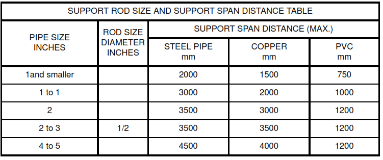
12.7 Pipe Supports
12.7.1 Suspended piping shall be supported with clevis or trapeze hangers and rods.
a. Spacing of hangers for steel and copper pipes shall be in conformance with Attachment 01,
Support Span Table.
b. Hangers shall be located at 500 mm on each side of valves 3 inches and larger. Block up pipe at
hanger for insulation.
12.7.2 Sway bracing shall be provided on hangers longer than 500 mm.
12.7.3 Vertical piping shall be supported with riser clamps secured to the piping and resting on the building
structure. Support shall be provided at each floor unless otherwise noted.
12.7.4 Insulation shall be installed continuously through hangers and rollers. Insulation shall be protected
by galvanized steel shields.
12.7.5 Pipe supports shall be arranged to prevent excessive deflection and to avoid excessive bending
stress.
12.7.6 Pipe shall be supported from inserts or anchors in concrete slabs.
12.7.7 Hubless Piping
a. Hangers shall be installed on the piping at each side of, and within 150 mm of, hubless pipe
coupling so the coupling shall bear no weight.
b. Hangers shall not installed on couplings.
c. Hangers shall be adequate to maintain alignment and to prevent sagging of the pipe.
d. Adequate provision shall be made to prevent shearing and twisting of the pipe and the joint.
12.8 Sleeves and Openings
12.8.1 Sleeves shall be provided for each pipe passing through walls, partitions, floors, roofs, and ceilings.
a. Pipe sleeves shall be set in place before concrete is placed.
b. For uninsulated pipe, sleeves shall be 2 pipe sizes larger than the pipe passing through, or
provide a minimum of 13 mm clearance between inside of sleeve and outside of the pipe.
c. For insulated pipe, sleeves shall be of adequate size to accommodate the full thickness of pipe
covering, with clearance for packing and caulking.
12.8.2 space between sleeve and pipe or pipe covering shall be caulked, using noncombustible,
permanently plastic, waterproof, nonstaining compound that leaves a smooth finished appearance, or
packed with noncombustible cotton, rope, or fiberglass to within 13 mm of both wall faces, and provide the
waterproof compound described above.
12.8.3 Finish and Escutcheons
a. Rough edges around sleeves shall be smoothed with plaster or spackling compound.
b. Escutcheons shall be installed on all pipes exposed to view where passing through walls, floors,
partitions, ceilings, and similar locations.
c. Escutcheons sized to fit pipe and covering.
d. Escutcheons shall be held in place with set screw or internal spring tension.
12.9 Field Wrapping Underground and Under Slab Piping
12.9.1 Uncoated pipe and fittings, and coated pipe which has damaged coating shall be wrapped.
12.9.2 Pipe and fittings shall be cleaned to bare metal.
12.9.3 1-mil minimum thickness polyethylene tape shall be used.
12.9.4 Tape shall be Initially stretched to conform to the surface while spirally half-wrapping.
12.9.5 A second layer, half-lapped and spiraled shall be applied as above, but with spirals perpendicular to
the first wrapping.
12.10 Cleanouts
12.10.1 Construction Manager’s approval of locations shall be secured for locations of cleanouts in
finished areas prior to installation.
12.10.2 Cleanouts shall be the same nominal size as the pipes they serve; except where cleanouts are
required in pipes 4 inches and larger, provide 4-inch cleanouts.
12.10.3 Cleanouts shall be made accessible. After pressure tests are made and approved, Cleanout
threads shall be thoroughly graphited.
12.11 Valves
12.11.1 Valves in water systems shall be installed and located and arranged so as to give complete
regulation of apparatus, equipment, and fixtures.
12.11.2 Valves shall be provided in at least the following locations:
a. In branches and headers of water piping serving a group of fixtures.
b. On both sides of apparatus and equipment.
c. For shutoff of risers and branch mains.
d. For flushing and sterilizing the system.
e. Where shown on the drawings.
12.11.3 Valves shall be located for easy accessibility and maintenance.
12.11.4 Hose bibbs shall be provided where areas wash down is required.
12.12 Water Hammer Arresters
12.12.1 Water hammer arresters shall be provided on hot water lines and cold water lines.
12.12.2 Quick closing valves, solenoids, isolated plumbing fixtures, and supply headers at plumbing fixture
groups shall be Installed in upright position. .
12.12.3 Arresters shall be located and sized in accordance with PDI Standard WH 201.
12.12.4 Water hammer arrestors shall be Installed behind access panels.
12.13 Valve and Pipe Identification
12.13.1 Valves and Equipment Charts : 2 typewritten charts shall be furnished, no less than 205 mm by 250
mm, including area plan of building, showing the assigned valve and equipment numbers, and the area or
parts of system controlled by each valve. Charts shall be mounted on stiff backing and delivered to
Construction Manager.
12.13.2 Valve Tags
a. Tag consisting of a 50 mm diameter, 20-gauge stainless steel disc for each main and branch line
shutoff valve or cock shall be provided . Tags shall be fastened in place by a continuous 3 mm steel
ring around the valve stem.
b. Discs shall be stamped with a number corresponding to the identification number shown on the
valve chart and with the service designation.
12.14 Pipe Identification
After completion of piping and finish painting, and before lines are connected to equipment or fixtures, each
individual pipe shall be marked, including pipes concealed above ceiling and in walls, for quick and easy
identification and direction of flow with markers and banding. Coding shall comply with ASME A13.1,
“Scheme for the Identification of Pipe Systems.”
12.15 Plumbing Fixture Installation
12.15.1 Fixtures shall be set level and in proper alignment with respect to walls and floors, and with fixtures
equally spaced.
12.15.2 Supplies shall be in proper alignment with fixtures and with each other.
12.15.3 Flush valves shall be installed in alignment with the fixture, without vertical or horizontal offsets.
12.15.4 Wall-mounted and floor-mounted fixtures shall be grouted watertight where the fixtures are in
contact with walls and floors.
12.15.5 Deck-mounted trim shall be caulked at the time of assembly, including fixture and
casework-mounted. Self-rimming sinks installed in casework shall be caulked. 1-part mildew-resistant
white silicone caulking compound shall be used.
13. Cleaning, Testing and Balance
13.1 Hot and cold water system shall be disinfected as per attachments 4.
13.2 Other testing and Adjusting
13.2.1 Personnel and equipment shall be provided, and arranged by contractor. Contractor shall pay the
costs of required tests and inspections required by governmental agencies having jurisdiction.
13.2.2 Soil, waste and vent, laboratory waste and vent, roof drainage, oily water, domestic and industrial
water systems shall be tested in conformance with the plumbing code requirements. The following
minimum tests shall be performed in the presence of Company. Lines except the sewer and vent lines, shall
be hydrostatically tested at 7.03 kg/cm2. Waste and vent lines shall be tested by plugging lower opens and
filling the complete system with water to provide a minimum of 3,048 mm water column (WC) hydrostatic
head over the tested system.
13.2.3 Where tests show materials or workmanship to be deficient, work shall be replaced or repaired as
necessary, and tests shall repeated until the specified standards are achieved. Caulk, glue or otherwise
shall not be used as a method to “plug” leak.
13.2.4 Systems shall be adjusted to optimum standards of operation.
13.3 Identification of Cleaned Items
13.3.1 Systems shall be tagged when tagging is required by the cleaning procedure. In such cases,
contractor shall provide and install a waterproof tag for cleaned items at all valves and connections to
avoid subsequent exposure to contamination and to identify potential hazard. The tag shall indicate that
the system has been cleaned and is ready for commissioning. Special restrictions regarding sealing
and/or pressurizing shall be clearly stated. The date of completion shall be shown.
Example:
CAUTION
KEEP SEALED UNTIL COMMISSIONING
Internally cleaned and pressurized
(Date)
13.3.2 Tag shall be yellow with black letters and at least 200 mm by 250 mm, secured with 14 gage
stainless steel wire.
14. As Built Drawings
14.1 Upon completion of the work under this contract, the contractor shall furnish a complete set of as-built
drawings which show all changes and revisions that were made up to the time the work was completed
and accepted. These drawings shall also show accurate dimensioned locations and elevations,
referenced to the base datum, of all buried or concealed pipe lines, valves, plugged tees, and capped
ends.
14.2 The drawings shall consist of one set of Xerox copies of the latest revision of the contract drawings
that have been marked up to show the required information. Company will furnish a set of prints to the
contractor.
14.3 If the contractor had previously submitted a complete set of shop drawings which were approved by
Company, then a marked up set of such drawings shall be acceptable.
15. Attachments
ATTACHMENT 1
ATTACHMENT 2


ATTACHMENT 3
Cleaning Procedures after Installation
Cleaning Requirements for Gaseous Oxygen Service Piping and Equipment
A. Scope of Procedure
1. This document is not intended to define the methods to be employed in arriving at an acceptable level of
cleanliness, but rather is intended to define acceptability criteria and minimum inspection requirements. It is
anticipated that the most efficient means of attaining an acceptable level of cleanliness will be best
determined by the contractor based on a review of the piping system and an evaluation of the condition of
the piping prior to cleaning. Pressure testing shall be completed before cleaning operations are performed.
2. Basic requirements for preservation of cleanliness are addressed.
B. Preparation for Cleaning
1. Refer to applicable cleaning procedures for preparation requirements.
2. Precleaned items (e.g., equipment, instrumentation, valves, gaskets, etc.) shall not be installed prior to
final inspection and acceptance of the system. The use of temporary pipe spools may be required to
complete the test circuit.
C. Materials
The contractor shall determine the cleaning method(s) which will most economically and efficiently provide
the required level of cleanliness. Safety and material disposal shall be considered in the selection of
methods and materials to be used.
D. Equipment
The equipment required shall be defined by the cleaning method(s) selected.
E. Cleaning Procedure
Cleaning shall be in accordance with CGA G4.1. The contractor shall submit a detailed proposed cleaning
procedure for approval. Submittals shall satisfy the requirements of Section 6.0 of this specification.
Clean steam condensate is normally used for water. Hard water which could precipitate calcareous
deposits on hot metal surfaces shall not used.
F. Chemical Solution and Rinse Disposal
Refer to applicable cleaning procedures for disposal requirements.
G. Degree of Cleaning
1. As a minimum, it is critical that any cleaning procedure and its inspection methods assure that none of
the following remain:
a. Hydrocarbons (oils, greases, etc.)
b. Nonapproved pipe thread or gasket sealants
c. Moisture
d. Paint, varnishes, or other coatings such as organic rust preventative coatings
e. Loose materials of any type (e.g., mill scale, rust, dirt, weld spatter, etc.)
f. Lint residue exceeding the fiber count recommendations established by CGA G4.1
H. Inspection Procedure
1. In evaluating the level of cleanliness, as a minimum the methods of inspection listed below shall be
employed. Other methods may also be employed to the extent that they are deemed beneficial.
a. All visually accessible areas shall be examined under strong white light as described by the CGA
G4.1 section addressing “Direct Visual Inspection (White Light)”.
b. All visually accessible areas shall be examined under “black” light as described by the CGA
G4.1 section addressing “Direct Visual Inspection (Ultraviolet Light)”.
c. Wipe tests shall be used to inspect visually inaccessible areas as described by the CGA G4.1
section addressing “Wipe Test”. These tests shall be used to the extent necessary to assure the
acceptability of the level of cleanliness in visually inaccessible areas. Every effort shall be made to
identify and inspect areas particularly subject to cleaning difficulties.
Note: It may be necessary to supplement ultraviolet or “black” light tests with other forms of testing
(water break tests, solvent purity, etc.). Certain organic oils such as castor and fish oil do not
fluoresce, and occasionally other materials which are not considered to be harmful contaminates will
fluoresce. In the latter case, the inspector shall determine the extent of additional cleaning
required to verify that the fluorescing material is not a harmful contaminant.
In the absence of other approved procedures, supplemental tests shall conform to testing
procedures described in CGA G4.1.
d. Visual examination shall be supplemented with bore-scopes, mirrors, and other aids, as
necessary, to properly examine inaccessible or difficult to see surfaces. Lights shall be positioned to
prevent glare on the surfaces being examined.
2. Joint inspection and acceptance by Contractor inspectors shall be required.
3. Contractor shall record cleaning results.
I. Post Cleaning Procedures
1. Once the level of cleanliness has been accepted by the Contractor, precleaned items shall
be installed in the system. Prior to installation, the cleanliness of such items shall be verified.
2. It is essential that the level of cleanliness achieved be maintained up until the time the system is
commissioned. The proposed cleaning procedure shall clearly state the specific procedures to be used in
this effort.
In the absence of other approved methods, the following steps shall be taken:
a. Immediately upon inspection acceptance, system shall be purged with dry oil-free nitrogen.
Openings shall be sealed and assured that a positive pressure is maintained within the system.
b. Tagging shall conform to the requirements of Section 13.3 of this document. The tags shall
indicate “Cleaned for Oxygen Service”. Instructions shall specify that the system remain sealed until
directly before the time of installation.
3. When an interior corrosion prevention coating is used for lines in oxygen service, the specific product
shall be approved. Organic compounds are prohibited in Oxygen service.
ATTACHMENT 4
Cleaning Procedure after Installation
Potable Water System Flushing and Disinfecting
A. Scope of Procedure
1. This procedure covers flushing and disinfecting of above and below ground potable water piping
systems after assembly, erection, and completion of pressure testing.
2. Contractor shall assure compliance with all federal, state, and local laws and regulations that may be
applicable.
B. Preparation for Cleaning Procedure
1. All pipe runs and joints shall be visually examined for proper installation and continuity.
2. Equipment that has restricted flow passages or inaccessible areas where sediment could collect, shall
either be bypassed or removed and replaced by a spool piece.
C. Materials
1. Flushing medium: potable water
2. Disinfectant: Forms of Chlorine can be calcium hypochlorite, sodium hypochlorite, or liquid chlorine
packaged in steel cylinders.
Note!!! Liquid chlorine must be used in conjunction with a chlorinator.
D. Equipment
Dependent on system to be disinfected.
E. Cleaning Procedure
1. Flushing Procedure prior to disinfecting.
a. All pipelines shall be flushed with potable water before disinfecting. Minimum flushing velocity
should be 0.75 meters per second for water mains.
b. Flushing operations shall continue until water discharges are clear and free from turbidity and
extraneous materials.
c. Upon completion of the flushing operation, systems shall be drained and all items previously
removed, bypassed, or disassembled shall be reinstalled, reassembled, and made ready for the
disinfecting procedure.
2. Disinfecting Procedure
a. Piping systems shall be filled with a chlorine solution and left standing for an adequate contact
period. A safety lock-out / tag-out system shall be used at each user station (e.g, sink, water fountain,
etc.) to assure that personnel are protected against accidental exposure to chlorine solution.
Note!!! Contact time shall be in accordance with AWWA C651, latest edition.
b. Chlorine Application
(1.) For Large systems, a concentrated chlorine solution feed can be proportioned with the incoming
potable water filling the system.
(2) On small systems, the chlorine solution can be mixed in a container to the required concentration
and fed into the piping by gravity feed or pump.
3. Post-Flushing Procedure
After the applicable contact period, the heavily chlorinated water shall be flushed from the system with
potable water until the chlorine concentration in the water leaving the system is no higher than that in the
incoming potable water, or less than 1 ppm.
F. Chemical Solution and Rinse Disposal
1. Outlet pipes or nozzles at flushing discharges shall be directed to a safe location where chance of
damage from disposal of flushing water is minimal.
2. All spent chemical solutions and rinses must be disposed of in an environmentally acceptable manner.
G. Degree of Cleaning
1. Removal of all loose non-adherent material together with all adherent material that could break away
during operation of the equipment.
2. Achieve disinfection of contaminants harmful to human health if consumed.
H. Inspection Procedure
1. Inspection shall be in accordance with AWWA C651, latest edition.
2. Contractor shall record cleaning results. Cleaning records shall include certified laboratory water
sample reports verifying acceptable system cleanliness.
I. Post-Cleaning Procedure
Tag components in accordance with Section 13.3 of this specification. Tag shall indicate “Disinfected”.