The purpose of this article is to establish guidelines in designing and selecting Captive Motor–Transformers and specific design techniques used to enhance and assess the design practices. Moreover, reliability issues will be explored, so that the overall life-cycle cost of a captive motor-transformer installation can be minimized.
Designing and Selecting Captive Motor – Transformers – SABP-P-11 Download
Industry Codes and Standards
American National Standards Institute
ANSI C57.12.00 Standard General Requirements for Liquid-Immersed Distribution, Power, and Regulating Transformers
ANSI C57.12.10 American National Standard for Transformers 230 kV and below 833/958 through 8333/10,417 kVA, Single-Phase, and 750/862 through 60,000/80,000/100,000 kVA, Three-Phase without load Tap Changing; and 3750/4687 through 60,000/80,000/100,000 kVA with Load Tap Changing – Safety Requirements
ANSI/IEEE C37-96 IEEE Guide for AC Motor Protection
NEMA MG 1 Motors and Generators
Captive Motor–Transformers Overview
Selecting the proper rating and characteristics for a captive transformer of a large motor are extremely important to the reliability of our electrical power systems. The captive transformer and motor may serve a variety of different loads and operate continuously or experience multiple starts or pulses. The type of motor load, environmental conditions, voltage drop, and desired energy efficiencies are important engineering factors that must be considered when selecting and sizing a captive transformer.
What is a Captive Motor–Transformers?
Captive Motor–Transformers is a transformer whose output is dedicated to a single piece of utilization equipment, i.e., motor. Captive motor-transformer schemes are used successfully in some Saudi Aramco facilities. However, they shall be considered as special case, since their application is different from power transformers in that they supply only motors which affect the functionality of the electrical system during starting.
Applying Captive Motor–Transformers
Use of captive motor–transformers requires different considerations than direct coupled motor applications. When the motor is coupled with a captive transformer, the motor is now an integral part of the captive transformer and visa-versa. Successful operation of both the motor and the captive transformer depend upon the manufacturers’ of both the captive transformer and motor engineering the system together.
Deciding whether to use a Captive Motor–Transformer
Economic Evaluation
The associated cost saving cannot be determined for exact. The majority of cases there is a potential dollar saving in using the motor-captive transformer combination. In addition to the probable economic benefit, the combination inherently has many other major advantages.
These advantages, as listed next, should be considered and evaluated even where the cost of the combination is equal or slightly higher.
Benefits
Use of a dedicated captive transformer for a given motor installation provides a number of advantages:
Reduce voltage flicker and fault levels at the motor and into the system from the motor and an increase in tolerance of nearby unbalanced loads.
Give the opportunity to optimize design of motor relative to supply voltage vs. HP.
Ability to isolate the ground fault networks so that motor ground detection is independent of supply system ground detection.
Of course, due to transformer impedance, it is necessary to allow for lower voltage during starting. Also, additional transformer protection features are required.
Typical Applications
There are typical applications for a captive motor-transformer design as follows:
The transformer and motor can be energized at the same time by a single breaker in the primary circuit of the transformer as shown in Appendix A. In this case, the captive transformer is under continuous load. This is considered as cost-effective design. However, the design of captive transformer impedance shall consider the core magnetization requirements when using HV side breaker only.
It is possible to find a transformer used in a scheme where the downstream load has its own dedicated circuit breaker. This approach has the advantages of limiting the inrush current and magnetization effects by energizing the transformer first, and then the downstream load would be connected only after transformer energization.
In a remote operation, the captive transformer can be installed at the motor, and voltage drop due to a long run of cable would be minimized. Another advantage is that the voltage drop during motor starting is isolated from other loads. The captive transformer for line starting is to ensure a higher starting torque for the process.
Installing the Captive Motor–Transformers
Matching Motor/Captive Transformers with Load
In power systems, there are many devices whose proper size is critical to the design of a power delivery system. One of the most important is the power transformer. There are several factors involved in the process of sizing a transformer. ANSI/IEEE and IEC standards provide a set of guidelines that list these factors and how they can be used to determine if a transformer can handle its required operating load. Inadequately sized transformers may shorten the equipment’s operating life or cause overloading failures.
The design method considers several factors like ambient temperature, altitude, cooling stage and type (dry or liquid fill). When sizing a transformer, it is also very important to consider the expected future growth of the required load. The transformers short-circuit requirement, transformer impedance, and basic impulse level (BIL), are also considered to have a proper MVA transformer size.
The data required for the transformer MVA sizing calculation are as follows:
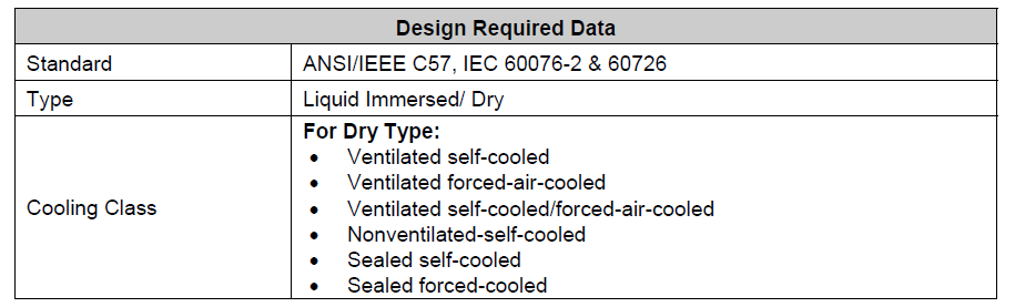
| Liquid Immersed: • Self-cooled • Self-cooled/ forced-air-cooled • Self-cooled/ forced-air-cooled/ • Forced-liquid-cooled |
|
| Temperature Rise | Transformer ratings are non-forced cooled ratings at 65°C temperature rise. Specified transformer ratings are based on ANSI standard 65°C rise over a 30°C average ambient. The transformers kVA rating has been increased (de-rated) as required by S. Aramco Engineering Standards to obtain a satisfactory site rating for ambient temperatures higher than 30°C. |
| Primary Winding kV Rating1 | The nominal system voltages and grounding as per SAES-P-100 Table 1. |
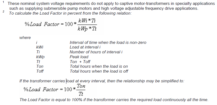
| Growth factor | The growth factor is an allowance for future growth. This percent value indicates how much future load increase should be expected for the given transformer. The growth factor is used for calculating the required rated MVA of the transformer. |
| Load Factor | The load factor is defined as the ratio of the average load to the peak load over a designated period of time. |
| Altitude | The altitude shall not exceed 3300 ft (1000 m) as per SAES-P-121. |
| Ambient Temperature | As per SAES-P-100 |
| BIL | ANSI has categorized the figures based on HV BIL, LV Voltage and whether it is with or without LTC. |
| Primary/Secondary SC kA requirement | The %Z value is determined based on the primary SC current and the full load current of the required MVA load. The BIL rating of the transformer is used to determine the minimum impedance the transformer should have in case the required SC current is too high. |
| Operating load/ Connected load | Operating load means loads connected and energized, while connected load means total loads connected to a transformer. Either the operating or connected loads are used for sizing calculations. |
Power Transformer MVA Sizing calculation complies with the following ANSI/IEEE standard:
1. ANSI/IEEE C57
2. IEC 60076-2 (liquid)
3. IEC 60726 (Dry)
The motor/captive transformer combination acts as a reduced voltage starter. While this is an advantage, it may also prove to be a problem. Consideration must always be given to the starting torque requirements of the mechanical load. It is fundamental that the motor must, at all speeds, be capable of delivering accelerating torque in excess of that required by the load. The motor speed-torque and speed-current curves were obtained by use of a computer program using actual motor constants and with provision for including system impedance and transformer impedance ahead of the motor. In the event that the initial motor design does not provide adequate torque margin over the entire speed range, the computer program facilitates reshaping the torque curves.
Another important consideration is that of impact loading on the transformer during starting. In the motor/captive transformer combination, the transformer kVA rating closely approximates that of the motor kVA requirement. Under starting conditions this imposes a sizeable thermal and impact load on the transformer.
Protection
The protection requirements for a large captive motor–transformer configuration are a complex combination of the different needs for protection of the motor, transformer, and process. The first tradeoff the designer will face is to decide which of the motor, transformer, or process is considered more critical to save. Another important determination is the relative importance of the available space for equipment and allowable capital investment, compared with the need for process reliability. Higher reliability will require implementing a fully developed protection, control, and monitoring system. The final captive motor–transformer configuration and the level of applied protection, monitoring and control will depend on individual answers to these questions.
When a large captive motor–transformer configuration is a considerable portion of total capital costs, a separate protection system for each piece of equipment is usually applied. This means that the transformer and the motor will each have its own dedicated circuit breaker and several sets of current transformers (CTs) and potential transformers (PTs). The applied protection philosophy is a simple superposition of typical motor and transformer protection with possible addition of a common differential protection for the overall system, similar to a generator–unit transformer overall differential protection. The operation of this protection should be blocked, using 52a contacts, if both breakers are not closed. In this way, when the transformer is energized, only its own differential protection will be employed; the overall differential will be blocked.
Motor relaying is designed to protect against some or all of the following abnormal conditions:
a) Overload (thermal),
b) Short circuit,
c) Under voltage and reverse phase sequence,
d) Stalled rotor,
e) Ground faults,
f) Single phase,
g) Current unbalance, and
h) Under frequency.
With the motor/captive transformer combination, the determination of which complement of relays to utilize should be appraised with the possibility of equivalent or better protection for less cost. In making this appraisal, consideration should be given to the following:
The grounding and ground relay alternative results in sensitive ground fault protection for the subsystem. With fast tripping on the first ground fault and recognizing the fact that most electrical faults in motors originate as line to ground faults, consideration should be given to the elimination of motor differential protection.
If the no-trip option on the first subsystem ground fault is exercised, consideration should be given to using a self-balancing differential relaying system to protect against phase-to-phase faults in the motor.
To protect against internal transformer faults, consideration may be given to the use of a sudden pressure relay and transformer differential protection.
If single-phase protection is deemed necessary, consideration should be given to the use of the less expensive negative sequence voltage relay.
These and many other points should be considered before investing in a protective system. The relaying should be selected after careful consideration of the preceding options.
During abnormal system conditions, the voltage on the system might be severely reduced or completely lost. When the system voltage is returned to normal, the magnitude of the inrush current to the motor is reduced due to the added impedance of the captive transformer. This reduces the impact stresses applied to the motor.
The captive transformer acts as a buffer to any system voltage disturbance (lightning surges, switches surges, etc.) thus reducing abnormal stresses on the motor insulation system. With the motor starting contacts on the transformer primary, no switching surges are present directly at the motor terminals.
Power System Considerations
It is imperative to develop the captive-motor transformer requirements early in the design stages to make it possible to correlate power system parameters. Considering the overall system will facilitate mainly meeting both normal-load and short-circuit requirements.
There are many factors that must be considered when selecting a captive-motor transformer as follows.
Voltage Drop Limitations
During the motor starting period, the starting motor appears to the system as a small impedance connected to a bus. It draws a large current from the system, about six times the motor rated current, which therefore results in voltage drops in the system and poses disturbances to the normal operation of other system loads. Since the motor acceleration torque is dependent on motor terminal voltage, in some cases the starting motor may not be able to reach its rated speed due to extremely low terminal voltage. This makes it necessary to perform a motor starting analysis. The purpose of performing a motor starting study is twofold: to investigate whether the starting motor can be successfully started under the operating conditions, and to see if starting the motor will seriously impede the normal operation of other loads in the system.
One engineering factor that must be considered when selecting a captive transformer is voltage drop at the terminals during motor starting. Per-unit motor torque will vary with the per-unit voltage squared. If the terminal voltage is 0.80 per unit during starting, the delivered motor torque will be 0.64 per unit. This may or may not be sufficient torque to accelerate the load to its full speed depending on the WK2 inertia of the rotor, coupling, gearbox, and driven load.
The two major transformer parameters that can be varied to reduce voltage drop are percent impedance and kVA rating. Increasing the kVA rating of the captive transformer while keeping the percent impedance constant, reduces the voltage drop through the transformer by approximately the ratio of the lower kVA rating to the increased kVA rating. The per-unit voltage available during initial motor starting can be found by using a voltage divider equation that calculates the ratio of the motor per-unit impedance to system short-circuit impedance plus motor per-unit impedance as follows:
Vs /Vi = Xm /(Xs + Xm) (1)
Where:
Vs per-unit starting voltage;
Vi per-unit initial or nominal voltage;
Xm per-unit motor starting impedance;
Xs per-unit system short circuit impedance.
Equation (1) calculates the initial voltage at the instant the motor is started. Since varies as the motor accelerates to full speed, the motor terminal voltage and the resultant torque also will vary.
Increasing the short-circuit availability (stiffness) of the system by increasing the size of the captive transformer with a constant percent impedance reduces the system short-circuit impedance in the denominator, thus increasing the available motor starting voltage. Another method of increasing available motor terminal voltage is to specify a lower impedance transformer. Most transformer manufacturers have standard impedance offerings, such as 5.50% which is common percent impedance for medium-voltage transformers. Lowering the impedance will also increase the available short-circuit availability, thus reducing the voltage drop. Reducing the impedance below the standard impedance may increase the cost of the transformer. If the impedance is reduced below 5.00%, the cost of the transformer may increase substantially because of design changes required by the increased short-circuit forces on the transformer. The other criterion that must be verified in either case is that the momentary and interrupting ratings of the electrical switchgear are not exceeded.
Another consideration for selection of a captive transformer is the number of starts or pulses that the motor and transformer will experience. Each time a motor starts, significant forces are exerted on the transformer windings. Manufacturers utilize unique construction and design techniques for each type of transformer. Three types of transformers that can be used for captive motor installations include liquid, dry, and cast coil. The cast-coil transformer is really a special type of dry transformer.
In addition to the high inrush currents during motor starting, some captive transformer applications also have periodic high current pulses that place unusual thermal and mechanical duty on the transformer. Some examples of these applications include reciprocating compressors and pumps. The equivalent rms load for a typical load cycle of the motor should be calculated that includes motor starting, steady load, and pulsating load, if any.
Captive transformer manufacturer shall be consulted to choose the optimum low impedance versus short circuit availability, thus reducing the voltage drop.
Short-Circuit Capacity
Captive transformer is one approach to increase short circuit capability; therefore it is possible to reduce the inrush kVA. Together these two changes will result in an acceptable voltage drop on the system.
System stability is dependent upon several factors:
System three-phase short-circuit magnitude, and other factors like
Relaying time
Magnitude of impedances connecting various rotating devices to the source and to each other
Inertia of the rotating devices
Mechanical loads on the rotating devices.
In the design of a system containing large motors, it is advisable to study the system stability under the most adverse conditions of fault locations and clearing time. The study shall reveal that all dynamic loads are stable for all ground faults and some three-phase bolted faults.
Inrush Limiting
Starting a large motor gives rise to the considerations of the allowable voltage drop on the total system as well as satisfying the torque requirements of the drive system. To reduce the voltage drop on the high-voltage system, it is necessary to reduce the magnitude of the motor inrush kVA and/or increase the system’s three-phase short circuit (S/C) kVA. This is shown by the following formula:
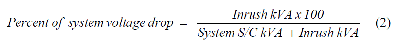
For example, for a desired maximum voltage drop of 15 %, the inrush kVA through the system cannot exceed 17.6 % of the system three-phase S/C kVA.
The use of the captive transformer introduces added impedance in series with the motor which reduces the inrush current to the motor/captive transformer combination from that of a motor started across the line. This reduces the mechanical forces on the motor windings and mechanical parts since these forces vary as the square of the inrush current.
Motor Speed-Torque Requirements
Reducing the inrush current also reduces the speed-torque capabilities of the motor. This results in a longer acceleration time for a given load speed-torque requirement. There is a greater margin in time between the acceleration time and the motor thermal limits when the captive transformer is used.
The standard motor at this reduced voltage will usually produce adequate accelerating torque for variable torque type loads such as fans, pumps, and centrifugal compressors starting unloaded. This, of course, must be checked, as will be described later, before going ahead with the application.
It should be noted that other steps may need to be taken in limiting inrush current where more severe restrictions are encountered. One alternative would be to specify higher than normal impedance in the transformer. Another would be to use a step-down transformer with load tap changing (LTC). With LTC, a lower than normal motor voltage can be selected during starting and acceleration and then rated voltage can be established when the drive is at full speed. Adding LTC would affect the economics discussed earlier more than added impedance, but both may be economically feasible.
System Grounding
Statistically, the predominant initial mode of electrical failure in a motor is line-to-ground. Thus, in many cases, it is advantageous to severely limit ground fault current.
The restricted ground-fault differential (87RGF) can be utilized. The 87RGF is a separate differential protection only for wye transformer windings and is useful to:
Determine the location of internal transformer faults.
Decrease the possibilities of line-to-ground faults escalating into three-phase faults.
Prevent widespread burning and subsequent replacement of motor stator laminations.
Eliminate the need for immediate tripping on the first ground fault with the resulting unscheduled outages of the process.
The captive transformer isolates the primary and secondary ground systems. This makes it possible to “tailor” the grounding system of each subsystem (captive transformer secondary, busduct/cablebus, and associated motor) independent of the primary system grounding considerations.
When capacitance-to-ground of subsystem is quite small, this gives the further option of utilizing a high-resistance grounding system that limits the resistive ground current to a value equal to the small subsystem charging current.
With this magnitude of ground fault current is not imperative to trip immediately on the first ground fault. A voltage relay across the grounding resistor can detect, with a high degree of sensitivity, a ground fault in each subsystem. This relay can either initiate an alarm or trip. If one options to alarm, an unscheduled outage may be prevented.
Cooling Class
The standard requires that power transformers be supplied with cooling fans which is a relatively inexpensive method used to increase the capacity of the transformers 25 to 33 percent over their base OA rating. Power transformers are primarily used to feed double-ended substations (substations that have two incomers, each feeding a separate bus and the buses are connected to a common bus tie circuit breaker usually operated in the open position). Consequently, each transformer supplies the load for only one bus. The loads are usually less than 50% of the transformer base OA rating. However, during transformer maintenance and some types of emergencies one transformer is out of service, the bus tie circuit breaker is closed connecting the two buses and one transformer must supply the loads for both buses. The transformers are sized so that the FA (fan cooled) rating is sufficient to carry the entire load. This provides a very efficient and economical way to size transformers that may only occasionally be required to carry loads in access of their base OA rating.
The captive transformer is dedicated to feed only the motor. Therefore, the transformer base OA rating could be selected to provide the power required by the motor. Additional capacity by installing cooling fans is unnecessary and the fans can be deleted.
Main Tank Monitoring
The main tank monitoring of captive transformer will furnish online diagnostics information to diagnose condition and properly detect imminent failures of power transformers. The monitoring has the merit of forcing the user to address the truly significant alarms and enhance the failures detection efficiency to 60%.
To have realistic design requirements, risk-economic analysis can be exercised. This will help avoiding extra cost by mandating the monitoring system. Transformer criticality and emergency loading rate shall be considered.
The ultimate criterion is to provide a database that has oil-filled transformers H2O and H2 activities trends.
The captive transformer monitoring fuel cell sensor can be used at the bottom oil sampling valve of transformer.
As per IEEE PC57.143 “Guide for Application of Monitoring Liquid-Immersed Transformers and Components”, the justification for on-line monitoring is driven by the need to increase the availability of power transformers, re-direction of time and/or operational-based maintenance to condition-based maintenance, asset and life management; and failure cause analysis. The PC57.143 guidelines should be used to determine the Transforms Monitoring System (TMS) risk/benefit analysis, sensor application, and TMS application.
